
Super-hydrophobic stearic acid layer formed on anodized high purified magnesium for improving corrosion resistance of bioabsorbable implants
2018-04-22 03:02:50SohrabKhalifehDavidBurleigh
Journal of Magnesium and Alloys 2018年4期
Sohrab Khalifeh,T.David Burleigh
Materials&Metallurgical Engineering Department,New Mexico Institute of Mining&Technology,Socorro,NM 87123,USA
Abstract Magnesium and its alloys are ideal candidates for bioabsorbable implants.However,they can dissolve too rapidly in the human body for most applications.In this research,high purified magnesium(HP-Mg)was coated with stearic acid(SA)to slow the corrosion rate of magnesium in simulated body fluid at 37±1°C.HP-Mg was anodized(AC and DC voltages)to form an oxide/hydroxide layer,and then it was immersed in a SA solution.The SA coated layer surface,anodized layer,and the thickness of the oxide/hydroxide layer were investigated with Scanning Electron Microscopy(SEM).Electrochemical impedance spectroscopy(EIS)and potentiodynamic polarization(PDP)were used to estimate the corrosion rate of HP-Mg specimens.The results confirm that the hydrophobic coating can decrease the corrosion rate of HP-Mg by more than 1000x.The protectiveness of coated layer for anodized specimens with AC voltage continue for 2 and 3 weeks.For the HP-Mg coated anodized with DC voltage,the coated layer could improve the corrosion resistance for only a few days.
Keywords:Magnesium;Biomaterials;Hydrophobic layer;Stearic acid;Simulated body fluid;Electrochemical impedance spectroscopy.∗Corresponding author.
1.Introduction
Biodegradable materials are being considered for temporary implants to cut the cost and the problems associated with the retrieval surgery[1,2].Bioabsorbable magnesium is being considered for the field of biomaterials,especially for orthopedic implants and heart vascular stents[3,4].Magnesium is an ideal biomaterial because of biocompatibility and low stress shielding[5-9].However,using magnesium and its alloys as biodegradable implants have been limited due to their rapid corrosion rate in the biological environment.Magnesium is dissolved via an electrochemical reaction in the presence of water due to the thermodynamic instability of magnesium.This chemical reaction produces magnesium hydroxide and hydrogen gas[10].The high concentration of chloride ions in the biological environment can lead to the pitting corrosion of magnesium,and consequently can cause serious problems such as hydrogen bubbles,caustic burning,loss of mechanical properties,and disappearance of the implant before complete healing[2,11-15].
Coating is one of the methods that has been considered to achieve this goal[16-25].As mentioned,biodegradation is one distinct advantage magnesium has as a biomaterial.Therefore,the coating layer should also dissolve and be biocompatible.The corrosion rate should be reduced by coating the implant,but not be permanently stopped.Stearic acid(SA)has been selected for use as a hydrophobic layer in this research.SA is a carboxylic acid and has the chemical formula CH3(CH2)16COOH[26,27].SA is non-toxic and biocompatible[27].Also,SA can cause a higher reduction in LDL cholesterol compared to other saturated fatty acids due to a lower probability of transforming SA into cholesterol esters[28].
Hydrophobic coatings are usually formed using at least two steps,the first step is surface preparation to ensure adequate adhesion to the hydrophobic layer,and the second step is forming the hydrophobic layer on the substrate.Ng et al.[29]conducted hydrothermal treatments to form an Mg(OH)2layer which provided sites to attach the SA coating which improve the corrosion resistance of pure Mg in Hank′s solution.The corrosion rate of coated magnesium was reduced 40 times in the 30 days immersion.Wang et al.[26]conducted chemical etching in H2SO4-H2O2method as the first step,but the SA coated layer protect the magnesium substrate only for several hours.

Table 1 Composition for HP-Mg used in this work.All compositions are given in weight percent.
In this paper,anodization was conducted as the first step of fabrication of an hydrophobic SA layer on magnesium in order to improve the corrosion resistance of the bioabsorbable magnesium and adhesion of the SA layer.High purified magnesium(HP-Mg)was anodized with AC and DC voltages to form oxide/hydroxide magnesium.The effect of different anodization parameters on the corrosion behavior of magnesium is reported herein.
2.Material and methods
2.1.Sample preparation
High purified magnesium(HP-Mg)was used in this research,and its chemical composition is given in Table 1.The HP-Mg rods were cut into 10 mm long cylinders,and cold mounted in epoxy with 2.55 cm2surface area.Next,the specimen surfaces were polished with sandpaper(600-1200 grit),and then with 1 μm oil-based diamond slurry,degreased with ethanol,washed with deionized water,and dried using flowing compressed air.
2.2.Anodization process
The anodizing processes were performed at 30±1,50±1,70±1°C for 10-240 s,at two groups of AC and DC voltages in the 275 ml aqueous electrolyte of borate benzoate,50%NaOH,and 1M KOH using a TecNu power supply(Dca:25/12-1Z)to provide multiple ranges of anodizing cell.The effect of surface preparation was investigated in this research.Two groups of HP-Mg were prepared,the first samples were ground to 1200 grit,and the next group was polished to 1 μm.The anodization potential was changed over the range from+4,+5,and+6 DC volts,and 120 AC volts.HP-Mg was connected to a positive terminal of the power supply,and the platinum counter electrode was connected to the negative terminal.After the anodizing process,the samples were rinsed with deionized water and dried by low pressure compressed air before coating with SA.During anodization with 120 volts AC,the reaction was very violent,and the temperature of the cell quickly increased about 10°C.
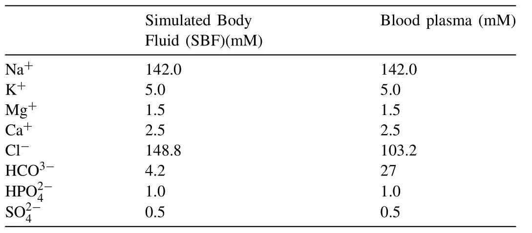
Table 2 SBF versus human blood plasma[31].
2.3.Electrolyte
The prepared 50%NaOH,and 1M KOH were purchased from Ricca chemical.The borate benzoate electrolyte was composed of 60 g/L NaOH,25 g/L Na2B4O7,20 g/L H3BO3,and 3 g/L NaBz(sodium benzoate:C6H5COONa)[30].During the anodizing experiments,the temperature of the electrolyte was held at 30± 1°C using a hot plate.
2.4.Hydrophobic layer formations
The formation process was performed using deposit coating.For this purpose,the anodized magnesium was immersed in the 0.05,0.1,and 0.15 mol/L SA in ethanol at room temperature for an hour.After immersion,the specimens were brought out from the solution and dried in the fume hood for 24 h.Surface morphologies of the anodized and coated specimen were carried out using scanning electron microscopy(SEM)(Hitachi S-3200,25 kV accelerating voltage,and 10 mm working distance).The water contact angles were measured at room temperature using the Kruss Drop Shape Analyzer(DSA25)to evaluate the hydrophobicity of coated layer.
2.5.Simulated Body Fluid(SBF)preparation
All corrosion tests were performed in a simulated human biological environment.The samples were immersed in simulated body fluid(SBF)at 37±1°C.The SBF was made according to the protocol for preparing SBF as described by Kokubo et al.[31].The ion concentrations of SBF are slightly different from human blood plasma as shown in Table 2.
2.6.Electrochemical measurements
Electrochemical impedance spectroscopy(EIS),and potentiodynamic polarization(PDP)of the specimens were mea-sured in SBF at 37±1°C using a PARSTAT 2263 potentiostat.For all measurements,a three-electrode electrochemical cell was used,with a KCl saturated calomel electrode(SCE)as a reference electrode and platinum wire as a counter electrode.At least three tests were performed for each condition with three different specimens to confirm the reproducibility of the EIS and PDP measurements.Short-term EIS test began 5-10 min after the specimens were immersed in SBF at 37±1°C,and run in the frequency range from 100 kHz to 100 mHz.The EIS measurement was conducted at the open circuit potential(OCP).Five data points were taken per decade of frequency.The magnitude of the cycle was 10 mV rms.Long-term EIS test was performed after six weeks immersion in SBF for assessment as an orthopedic implant.The temperature and pH were held at 37±1°C and 7.4 respectively during each week.SBF was replaced with fresh SBF weekly.The EIS tests were performed 10 min,1 h,4 h,1-,2-,4-,7-,14-,21-,28-,and 42-day during the immersion in SBF.
The PDP test was run immediately after the final EIS test.The initial potential was-250 mV relative to open circuit potential(OCP)and stopped at+1600 mV versus SCE scan at a rate of 10 mV/s.The high scan rate(10 mV/s)was performed because magnesium corroded too fast at a slower rate.Extrapolation of the cathodic and anodic regions of the Tafel slopes gave the corrosion rate,icorr(A/cm2)at Ecorr.
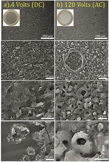
Fig.1.SEM images of anodized HP-Mg.Column(a)and(b)illustrate the anodized HP-Mg with+4 volts(DC)for 2 min and 120 volts(AC)for 10 s in different magnifications respectively(accelerating voltage:25 kV).
Polarization resistance,Rp,was determined from the EIS Bode plot.The impedance at 100 mHz(Rp+Rs)was reduced by the solution resistance at 100 kHz(Rs)to obtain Rp(polarization resistance).Then,Rpwas converted to the corrosion rate,icorr(A/cm2),by the following equation[32];

Where βaand βcare anodic and cathodic Tafel constants,respectively,and B is a proportionality constant,which was determined from PDP electrochemical data.icorr(A/cm2)from each EIS and PDP test was converted to the corrosion rate(mm/year)C.R.EIS/PDPby the following calculation;
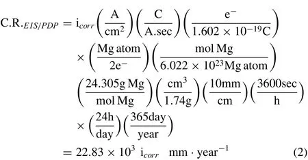
According to the oxidation reaction of magnesium(Mg→Mg2++2e-),it is assumed that two electrons are released for each atom of magnesium that dissolves in SBF.
3.Results
3.1.Surface characterization
The HP-Mg specimens were covered with a layer of Mg(OH)2/MgO after anodization process at+4,+5 and+6 V(DC)for 2-4 min and 120 V(AC)for 10 s.With the naked eye,the anodized surfaces were white and gray after the AC and DC anodization,respectively.Fig.1 illustrates the SEM images of the anodized specimens at different magnifications.Anodization provided the flaky structure and tubular morphology on the magnesium substrate for the anodized specimens at+4 volts(DC)and 120 volts(AC),respectively.The SEM image of a cross section of anodized HP-Mg shows a 10 μm average thickness for the oxide/hydroxide layer(Fig.2).The SEM images from anodized specimens with DC voltages could not show the oxide/hydroxide layer in 32,000x magnification,demonstrating that the oxide/hydroxide layer was in the nanometer range.The SEM morphology of the SA coated specimens are shown in Fig.3.
3.2.Hydrophobicity(Contact angle)
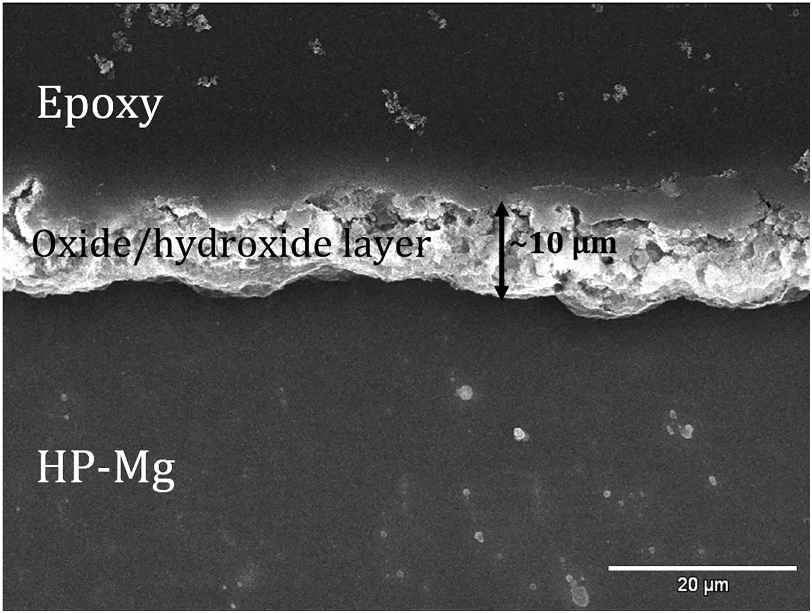
Fig.2.SEM image of cross section area of HP-Mg anodized with 120 volts(AC)for 10 s.The thickness of oxide/hydroxide layer is on average 10 μm thick.
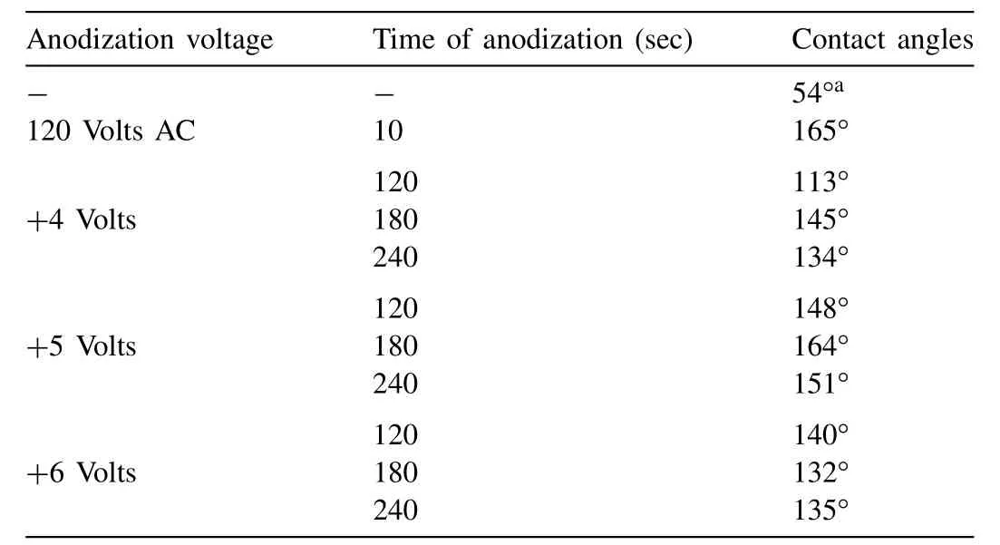
Table 3 The water contact angles of the coated HP-Mg specimens at different AC and DC voltages and times(30°C).
The water contact angles were measured to determine the hydrophobicity of the coated specimens.Fig.4 illustrated the drop shape of the water on the polished bare HP-Mg substrate and HP-Mg coated with SA.The coated HP-Mg specimens were polished to 1200 grit,anodized with 120 volts(AC)for 10 s(Fig.4-b)and+5 volts(DC)for 3 min(Fig.4-c),respectively at 30°C in borate benzoate,and immersed in 0.05 mol SA in ethanol for 60 min.The water contact angles of all the coated HP-Mg specimens at different DC voltages(+4 to+6 volts),for times(2-4 min)of anodization at 30°C are shown in Table 3.
3.3.Corrosion behavior(PDP and EIS results)
To estimate the corrosion behavior of coated HP-Mg,EIS and PDP methods were performed in SBF at 37±1°C.In order to investigate the influence of voltage,time,and temperature,the polished(1200 grit)magnesium specimens were anodized with+4,+5,and+6 volts for 2-4 min at 30,50,and 70°C in borate benzoate,then immersed in 0.05 mol/L SA in ethanol for 60 min.Fig.5 shows the representative EIS and PDP results showing triplicate samples which were anodized in 30°C borate benzoate,at+6 volts.The corrosion density,icorr(A/cm2)was extrapolated from the PDP curves,then converted to the corrosion rate(mm/year)with Eq.(2).The summary of corrosion rates of coated HP-Mg,anodized at different voltages(DC),times,and temperatures of anodization compared to polished bare HP-Mg were illustrated in Fig.6.The corrosion resistance was improved by increasing the time and voltage of anodization.The optimum corrosion rate(12 μm/year)belongs to the anodized HP-Mg with+4 volts for 4 min at 70°C.which provided the highest polarization resistance(Rp≃105Ω)among all coated specimens.The summary of the corrosion results from the EIS and PDP measurements are given in Table 4.
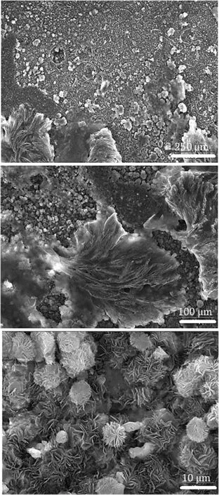
Fig.3.SEM images of SA layer on anodized HP-Mg with 120 volts(AC)for 10 s at different magnifications(accelerating voltage:25 kV).

Fig.4.The water contact angle of the drop shape of the water,(a)Polished bare HP-Mg,ground with 1200 grits,(b)Coated HP-Mg,ground with 1200 grit,anodized for 120 volts(AC)for 10 s,and(c)Coated HP-Mg,ground with 1200 grit,anodized for+5 volts and 3 min at 30°C in borate benzoate,and immersed in 0.05 mol/L SA in ethanol for 60 min.
Figs.7 and 8 illustrate the corrosion rate(mm/year)based on the EIS test and PDP results of polished bare and coated HP-Mg(anodized with AC current),respectively.The conversion constant,B,was estimated to be 0.07 V based on our PDP experiments.The coated specimens were anodized at different temperatures(30±1,50±1,and 70±1°C).The EIS and PDP results after immersion for 10 min in SBF confirmed that the corrosion rate of HP-Mg was significantly dropped by fabrication of the hydrophobic coating on the magnesium.Increasing the temperature of the borate benzoate electrolyte,also improved the corrosion resistance of HP-Mg.
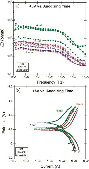
Fig.5.(a)EIS,(b)PDP results for the samples were anodized in borate benzoate,at+6 volts for 2-4 min at 30°C.
Fig.9 illustrates the corrosion rate of as-polished HP-Mg versus immersion time(during 42 days)in warm SBF in compared to coated HP-Mg with SA.The corrosion rates came from long-term EIS tests.
To find the best electrolyte to anodize magnesium,different types of electrolytes(KOH,NaOH,and NaBz)were investigated in this work.The polished(1200 grit)HP-Mg specimens were anodized with 4 volts for 2 min at different temperatures(30,50,and 70°C),then coated with SA(0.05 mol/L).The corrosion rates(mm/year)extracted from PDP measurement are shown in Fig.10.The PDP tests were performed after 15 min immersion in warm(37°C)SBF.The results show that the corrosion resistance of anodized HP-Mg specimens in KOH and NaBz were improved by increasing the temperature.However,the NaOH showed the opposite effect in that the corrosion rate increased with increasing the temperature of the electrolyte.
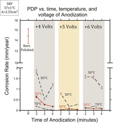
Fig.6.The corrosion rate(mm/year)extracted from PDP curves of coated,DC anodized HP-Mg specimens at different voltages,times,and temperatures of anodization compared to polished bare specimen.
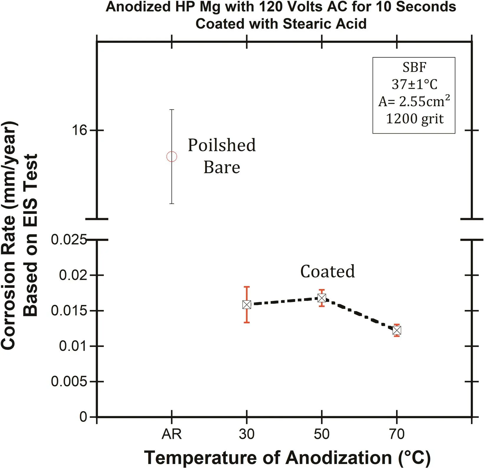
Fig.7.The effect of the AC anodizaing temperature on corrosion rate(mm/year)of HP-Mg based on EIS test in SBF at 37±1°C compared to polished bare HP-Mg.

Table 4 Summary of the corrosion results from EIS and PDP meeasurments(A=2.55 cm2).
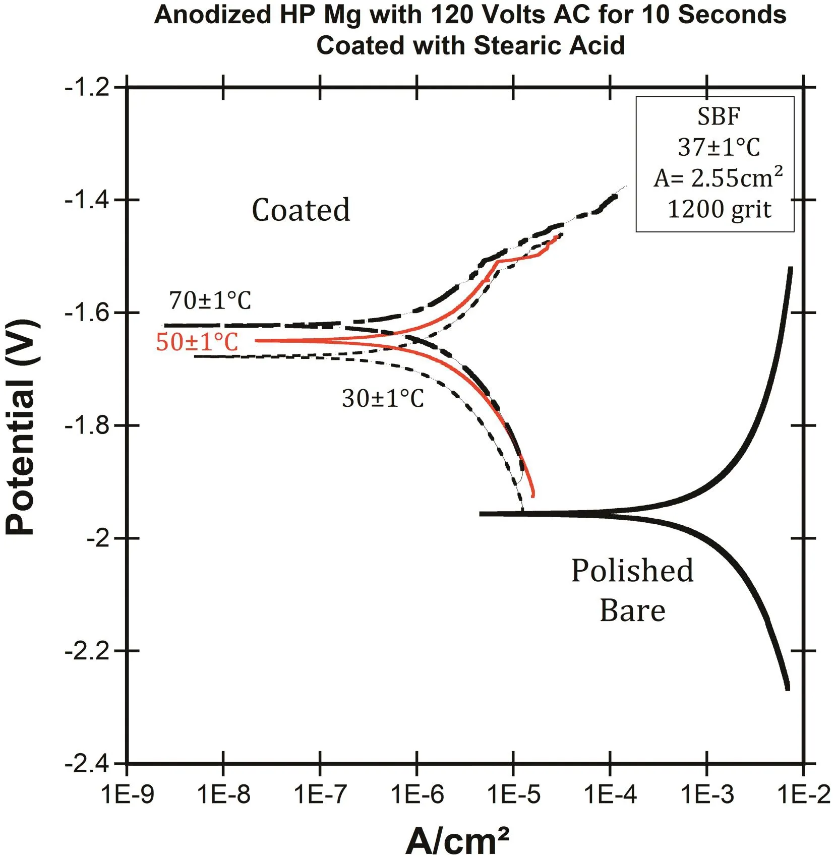
Fig.8.The effect of anodizaing temperature of coating process on PDP results of coated and polished bare HP-Mg in SBF at 37±1°C.
The PDP curves in Fig.11 did not depict a very different anodic polarization behavior for the coated samples which were immersed in the different SA concentrations.The coated specimens were polished(1200 grit),anodized with+4 volts(DC)for 2 min and 120 volts(AC)for 10 s in warm borate benzoate(30°C),then immersed in 0.05,0.1,and 0.15 mol/L SA in ethanol for 60 min.The results(Fig.11)reveal that the increasing SA concentration increased the corrosion potential but had a negligible effect on the corrosion resistance,and the corrosion rate was similar for 0.05,0.1,and 0.15 mol/L SA in ethanol.This might be because the SA reduced the anodic sites but did not reduce the cathodic sites.Therefore,the excess concentration of SA was not more effective at enhancing the corrosion resistance of magnesium.

Fig.9.The corrosion rate(mm/year)based on the EIS results in depends on immersion time in SBF at 37±1°C for polished bare and coated HP-Mg(AC and DC currents).
4.Discussion
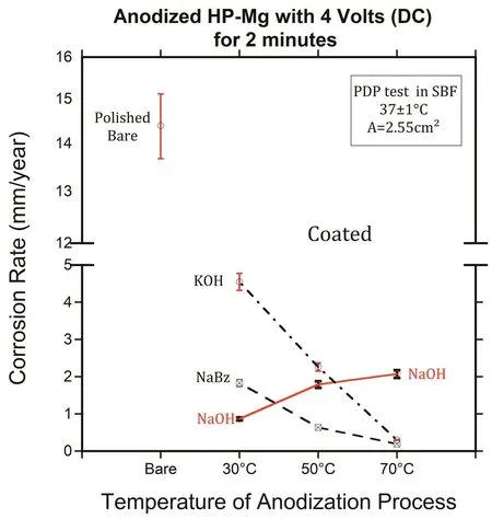
Fig.10.The corrosion rate(mm/year)extracted from PDP measurements of coated HP-specimens as a function of the electrolyte and temperature.
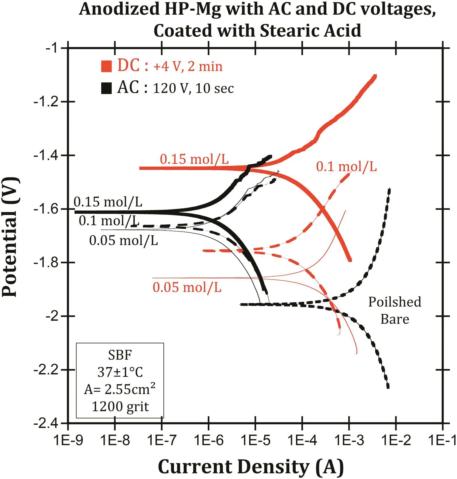
Fig.11.The potentiodynamic polarization curves in SBF at 37°C for different concentrations of SA.
Bioabsorption and biocompatibility are some advantages of magnesium when used as an orthopedic implant,along with less stress shielding and good strength to weight ratio.However,the poor corrosion resistance of magnesium in a biological environment con fines the use of magnesium as a bioabsorbable implant.Slowing the corrosion rate of magnesium by coating with biocompatible SA has been investigated in this research with different AC and DC voltages.We demonstrated that the coated layer obtained super-hydrophobicity(Fig.4-b,and c)in HP-Mg which was expected of SA layer.Based on the SEM images(Fig.1),the tubular and flaky structure formed by anodization process could be an appropriate substrate for the SA to form a hydrophobic layer.The tubular and flaky structures of magnesium oxide/hydroxide layer on the surface allow SA to penetrate to the HP-Mg substrate,also increasing the surface area of the magnesium binding with SA.The standard test(D3359-09)was performed to measure the adhesion of SA layer before immersion in SBF.This taping method has been used to measure adhesion of organic coatings.The results revealed that the excess amount of SA was removed with tape,but hydrophobic SA layer remained throughout the specimen surface.Therefore,the classification of the adhesion test was recognized as a 5B[33].
The polarization curves revealed that that the corrosion rate(Fig.6)of coated HP-Mg(anodized with DC voltage)was significantly decreased in SBF by the formation of the hydrophobic layer of SA on the magnesium substrate.The PDP results illustrated that the further improvement was achieved by increasing the temperature of the electrolyte(borate benzoate)during the anodization process.This might be due to the formation of higher porosity of the hydroxide/oxide layer,and consequently improving the binding between the magnesium substrate and the SA[34].The results also show that the corrosion resistance was improved by increasing the time and voltage of anodization due to the formation of a thicker magnesium hydroxide/oxide layer.The EIS and PDP results confirmed each other and illustrated that the measured corrosion rates in this research were consistent.
The effect of electrolyte temperature was investigated for anodized specimens with AC voltage(120 volts)the same as the DC voltages.The results show that the corrosion rate of coated HP-Mg was reduced by 1000x compared to polished bare HP-Mg,and reveal that with increasing the temperature of anodization to 70±1°C,the corrosion resistance of coated HP-Mg was improved 2x compared to 30±1°C,which showed the same behavior of the specimens that were anodized with DC voltages.
The EIS results at the long-term tests showed that the coating layer of coated(anodized with AC voltage)HP-Mg removed/broke down after 2 and 3 weeks immersion in SBF at 37±1°C and the corrosion resistance was reduced to the corrosion resistance of as-polished HP-Mg(Fig.9).However,the coated(anodized with DC voltage)HP-Mg specimen showed completely different behavior in compared to the specimens anodized with AC voltage.Fig.12 illustrates the photographic images of exposed as-polished and coated HP-Mg in SBF at 37±1°C for 1-day,1-,2-,3-,and 4-week immersion.The DC anodized coated specimen began to increase the corrosion rate after several hours of immersion in warm SBF which was continued for a week.This might be due to a thin layer of magnesium oxide/hydroxide on HP-Mg substrate and consequently inappropriate binding of SA and magnesium oxide/hydroxide substrate.The coated layer broke down in a short time of immersion,and the corrosion rate increased due to severe pitting corrosion in the presence of high concentration of chloride ions.The schematic representation of a mechanism of pitting corrosion in magnesium in the presence of chloride ions and produce the corrosion products and hydrogen gas is shown in Fig.13.The long-term EIS results showed that the corrosion rate of as-polished HP-Mg was reduced in half after 4 h immersion.This might be due to the formation of a thin layer of magnesium oxide/hydroxide on HP-Mg substrate,then start to increase due to break down the oxide/hydroxide layer.
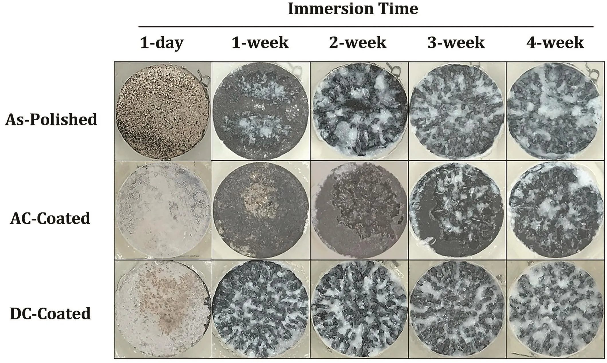
Fig.12.Photographic images of exposed as-polished and coated HP-Mg in SBF at 37±1°C for 1-day,1-,2-,3-,and 4-week immersion(not-drained).
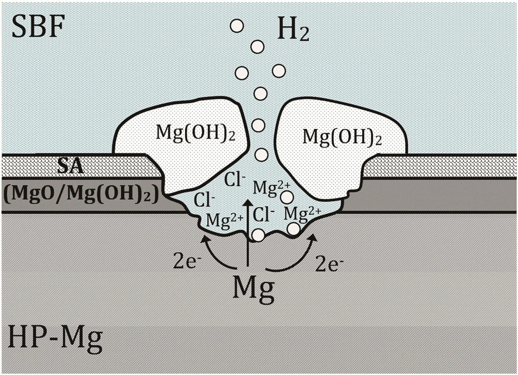
Fig.13.The schematic representation of a mechanism of pitting corrosion in HP-Mg in the presence of chloride ions and produce hydrogen gas.
The effect of SA concentration on corrosion behavior of HP-Mg was investigated(Fig.11).The results reveal that the increasing SA concentration for the coated HP-Mg(anodized AC and DC voltages)did not consistently improve the corrosion resistance.It seems that the amount of 0.05 mol/L SA in ethanol was enough to form the hydrophobic layer on magnesium substrate and the excess amount precipitates on hydrophobic layer,which would be dissolved in SBF during the EIS and PDP tests.Therefore,the excess concentration of SA was not more effective in improving the corrosion behavior of HP-Mg.
5.Conclusions
A hydrophobic layer was formed on HP-Mg to increase the corrosion resistance of magnesium for use as a bioabsorbable magnesium implant.Formation of a hydrophobic layer by anodization was effective for improving the corrosion resistance of HP-Mg.The results affirm the following:The formation of the SA layer on HP-Mg substrate provided super-hydrophobicity(165°and 164°for the anodized coated with DC and AC specimens,respectively).The optimum result was anodizing 1200 grit polished HP-Mg at+4 volts for 4 min in hot borate benzoate(70°C),and the corrosion rate was significantly decreased to 12 μm/year in SBF.Polished bare HP-Mg had a corrosion rate about 1000x higher at 15 mm/year.
The optimum process of anodized HP-Mg with 120 volts(AC)for 10 ss reduces the corrosion rate to 18 μm/year which was progressively reduced down to 0.011 mm/year by increasing the anodizing temperature to 70°C.The change in concentration of SA did not affect the corrosion behavior of HP-Mg.Long-term results showed that the anodized(AC voltage)coated layer of SA broke down after 2 and 3 weeks immersion in SBF and its effectiveness disappeared,while this period was less than a day for the anodized with DC voltage.
 Journal of Magnesium and Alloys2018年4期
- Journal of Magnesium and Alloys的其它文章
- Review on friction stir welding of magnesium alloys
- Rietveld re finement of powder X-ray diffraction,microstructural and mechanical studies of magnesium matrix composites processed by high energy ball milling
- Effect of Si addition on microstructure and wear properties of Mg-Sn as-cast alloys
- Atomistic calculations of surface and interfacial energies of Mg17Al12-Mg system
- Effect of process parameters on depth of penetration and topography of AZ91 magnesium alloy in abrasive water jet cutting
- Corrosion protection of AZ91D magnesium alloy by acerium-molybdenum coating-The effect of citric acid as an additive