Multi-Reconfigurable Band-Notched Coplanar Waveguide-Fed Slot Antenna
M. Lertwatechakul and C. Benjangkaprasert
1.Introduction
Recently, there are a lot of interests in researching of bandnotch antenna design concepts. The main objective of the designs is to mitigate electromagnetic interference (EMI)problems by introducing the intrinsic frequency filtering properties to an antenna. Hence, this guides to the benefit of the band-notch antenna about its capability to eliminate the interference of other existing communication services without the needs of using additional external band-stop filter devices.
Various band rejection techniques[1]-[3]were proposed, such as applying the split ring resonator (SRR)[2],[5], quarterwavelength resonator, adding slots into the radiator[8], adding slots into the ground[5],[6], adding slots inside the feeding line[11],adding embedded parasitic elements[1],[9],[10], and the hybrid techniques[3],[4]. Most of the mentioned techniques are not easy to implement, for example, the SRR method requires precisely double-side fabrication, adding slots onto the ground patch may increase the antenna size, adding slots into the radiator may introduce a significant effect to the designed antenna’s bandwidth, and adding slot into the tiny microstrip feeding line will be quite difficult to implement.Therefore, we used the embedded parasitic elements technique, as it is simple and it has the least problems on implementation than the others.
Furthermore, the emerging mobile applications also require antenna to be reconfigurable to achieve both of multifunction and adaptability properties, which will help the communication system to work more efficiently in the real-world congested communication environment. Using a set of micro-switches to reconfigure an antenna is a popular method which is used in[1],[4], and [6]-[8] to modify the configuration of an antenna.Therefore, we will apply the trick and use more switches to attach/detach parasitic elements to an antenna patch to achieve the multi-reconfigurable band-notched antenna.
This paper presents a design of a multi-reconfigurable band-notched coplanar waveguide (CPW)-fed[11],[12]slot antenna.The designed antenna could be used as a wideband antenna for IEEE 802.11 wireless local area networks (WLAN) standard of 2.4 GHz industrial scientific medical (ISM) band, 3.6 GHz,5 GHz ISM band, high-performance radio local area network(HIPERLAN)/2 (5.15 GHz to 5.35 GHz and 5.470 GHz to 5.725 GHz), and worldwide interoperability for microwave access (WiMAX) 3.5 GHz applications. By changing its microswitches status, the antenna could be reconfigured to stop one of the defined frequency bands: 4.5 GHz to 5.3 GHz, 3.4 GHz to 4.4 GHz, 2.925 GHz to 3.925 GHz, and 2.425 GHz to 3.6 GHz.
2.Antenna Analysis and Design
This section describes the analysis and design steps to achieve a multi-reconfigurable band-notched antenna[13],[14]for wideband applications. We model the antenna by using the CPW structure with the fr4 substrate of 1.60 mm thickness,its relative permittivity is 4.5 and the loss tangent is 0.02.The designed antenna impedance is targeted to be matched to 50 Ohm transmission line. Overall, the antenna design procedures could be decomposed to 3 major steps: The first step is to design a wideband antenna, the second step is to study on the effect of the shape and size of the added parasitic elements to the antenna bandwidth, and the final step is to add the reconfigurable property by applying micro-switches into the parasitic elements’ structure.
2.1 Design a CPW-Fed Wideband Antenna
In order to continue the ongoing work on reconfigurable antenna design[1], we model a CPW-fed wideband antenna in an octagonal shape with the size of 40 mm × 43 mm. The ground plane is etched to have an octagonal slot which contains a rectangular patch. The rectangular radiation patch is connected to a microstrip feeding line with the width of 2.6 mm. The overall design of the antenna is shown in Fig. 1 and the dimension parameters of the slot and the radiation patch are as followings: L = 31 mm, W = 23 mm, L1= 25 mm, and W1=17 mm. The radiation patch is rectangular with its size parameters: R1= 17.00 mm, R2= 13.00 mm, and R3=1.75 mm. The design gave a wideband antenna that can operate for applications in the 1.9 GHz to 6.5 GHz frequency range.

Fig. 1. CPW-fed wideband antenna.
2.2 Study on the Effect of Parasitic Elements
As described in [1], [9], and [10], adding parasitic elements to an antenna will result in creating a band-notch/band-notches within the antenna operating frequency. We use a pair of symmetric L-shaped strips and inverted-L-shaped as parasitic elements. The L-shaped strips are attached to the radiation patch at the top corners. Their structure and dimension parameters such as R5, R6, R7, R8, and R9are declared in Fig. 2.This introduced a band-notch to the CPW antenna.

Fig. 2. CPW-fed wideband antenna with L-shaped parasitic.
In order to understand the effect of adjusting the L-shaped parasitic elements on the generated band-notch[15]-[17], three schemes of the experiments are setup: Scheme 1) adjusting R7,Scheme 2) adjusting R8, and Scheme 3) adjusting R9. For each scheme, the other parameters are fixed except the interested parameters of the scheme. In general cases, R5= 1.0 mm, R6=0.6 mm, R7= 10.1 mm, R8= 0.5 mm, and R9= 4.0 mm.
• Scheme 1: Effect of adjusting R7of L-shaped strip
In this case, we adjusted R7to 9 mm, 10 mm, and 11 mm,respectively. The simulation results are shown in Fig. 3. It can be seen that the effect of increasing R7of the L-shaped strips is shifting the band-notch (the rejection band) to the lower frequency, and reducing the operating bandwidth of the antenna in high frequency whereas sustaining the band-notch width.
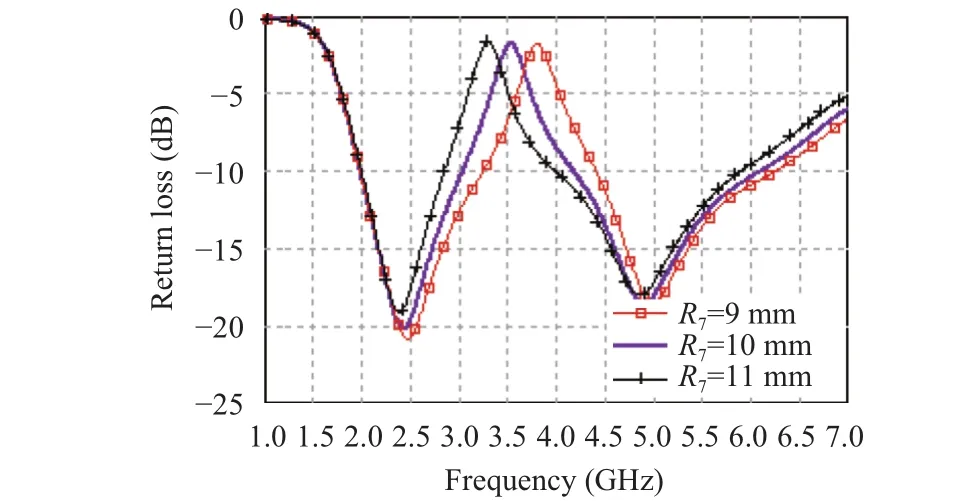
Fig. 3. Return loss of the antenna when adjusting R7.
• Scheme 2: Effect of adjusting R8of L-shaped strip
In this case, we have tried to adjust the width parameter R8of the L-shaped strips to be 0.25 mm, 0.50 mm, and 1.00 mm accordingly. The simulation results in Fig. 4 show that varying the parameter R8of the strips would also have an effect on the return loss of the antenna. It is noticeable that a wider parasitic L-shaped strip will lead to a larger notch that expands in both directions, the lower frequency and the higher frequency. The experiments also show that the width parameter R8has a very small effect on the lowest-operating frequency and the highestoperating frequency of the original antenna whereas the bandnotch width is sustained.

Fig. 4. Return loss of the antenna when adjusting R8.
• Scheme 3: Effect of adjusting R9of L-shaped strip
To study more on the effect of the size parameter R9of the parasitic L-shaped strips on the band rejection, we have adjusted R9to 3 mm, 4 mm, and 5 mm, respectively. The simulation results in Fig. 5 show that varying R9had an effect on the return loss as well, the longer R9will give the wider notch that expanded only in the lower frequency, whereas the original antenna’s lowest-operating frequency and highest-operating frequency are almost sustained.
The experiment results approve the assumption on the different shapes and sizes of parasitic elements, which would give different effects on the operative frequency of an antenna.Thus, we will utilize these properties to enhance the antenna design in the next step.

Fig. 5. Return loss of the antenna when adjusting R9.
2.3 Reconstruct the L-Shaped Parasitic Elements by Using Micro-Switches
Because of the different lengths of any part of the L-shaped parasitic elements could affect the produced band-notch. Thus,we modify the structure of the L-shaped parasitic elements to be a set of broken-line strips that can be reconstructed to be a pair of symmetric L-shaped strips of different lengths by setting the status of micro-switches, such as S1, S2, S3, S4, S5, S6, and S7.The structures of the modified antenna and the location of micro-switches are presented in Fig. 6 and Fig. 7, accordingly.The status of each micro-switch can be controlled separately.

Fig. 6. Modified structure of L-shaped parasitic strips.
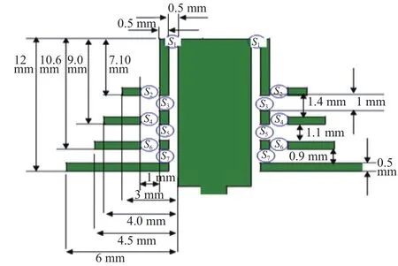
Fig. 7. Micro-switches location on L-shaped strips’ structure.
3.Simulation Results
By applying a different set of the micro-switches’ status,we configure the designed CPW-fed antenna to function as a single wideband antenna, or a dual-band antenna which works on one of following dual-band modes.
Single-band mode: All switches are OFF, the operating frequency of the antenna will be within the ranges of 1.90 GHz to 6.55 GHz as shown in Fig. 8.

Fig. 8. Return loss of the antenna when all switches are OFF.
Dual-band mode 1: Switches S1and S2are ON, the operating frequency will be within the ranges of 2.0 GHz to 4.5 GHz and 5.300 GHz to 6.575 GHz as shown in Fig. 9.
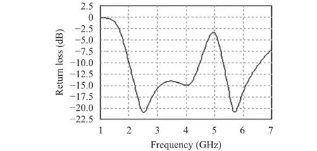
Fig. 9. Return loss of the antenna when switches S1 and S2 are ON.
Dual-band mode 2: Switches S1, S3, and S4are ON, the operating frequency will be within the ranges of 2.05 GHz to 3.40 GHz and 4.40 GHz to 6.45 GHz as shown in Fig. 10.

Fig. 10. Return loss of the antenna when switches S1, S3, and S4 are ON.
Dual-band mode 3: Switches S1, S3, S5, and S6are ON, the operating frequency will be within the ranges of 2.025 GHz to 2.925 GHz and 3.925 GHz to 6.350 GHz as shown in Fig. 11.
Dual-band mode 4: Switches S1, S3, S5, and S7are ON, the operating frequency will be within the ranges of 2.100 GHz to 2.425 GHz and 3.60 GHz to 5.95 GHz as shown in Fig. 12.
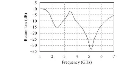
Fig. 11. Return loss of the antenna when switches S1, S3, S5, and S6 are ON.

Fig. 12. Return loss of the antenna when switches S1, S3, S5, and S7 are ON.
The comparisons of the return loss in all cases are shown in Fig. 13.
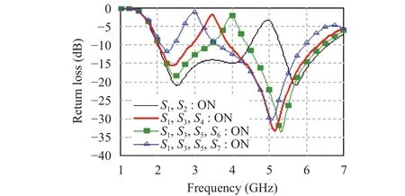
Fig. 13. Comparisons on the return loss of all cases.
4.Conclusions
The proposed design delivers an antenna with reconfigurable parasitic elements which can be reconstructed to different sizes of parameters R7and R9. As a conclusion from the experiments that increasing the strip length R7has an effect on shifting the band-notch to lower frequency and on decreasing the antenna bandwidth of the higher frequency where the width of the notch could be sustained. Whereas increasing the strip length R9has only an effect on slightly extending the band-notch to the lower frequency. Therefore,the sequence of schemes to change the micro-switches’status tends to give the longer S7and the longer S9, which will result in shifting the band-notch to the lower frequency band. The difference among the center of each adjacency notch is 1.0000 GHz, 0.4750 GHz, and 0.4125 GHz consequently where the band-notch’s width is slightly changed from 0.8 GHz to 1.0 GHz, and from 1.0 GHz to finally be 1.175 GHz.
Thus, by applying this concept we design an antenna that has multi-reconfigurable properties through adding a set of micro-switches into its structure. The designer could define different sets of length parameters to give the desired different band-notch characteristics to an antenna, conveniently.
[1]M. Lertwatechakul and C. Benjangkaprasert,“Reconfigurable band-notched CPW-fed slot antenna,” inProc. of the 4th Intl. Congress on Engineering and Information, 2015, pp. 415-420.
[2]H. Lalj, H. Grigue, and M. Drissi, “Design of reconfigurable band notches antenna for cognitive radio applications,” inProc. of Intl. Conf. on Wireless Engineering and Technology,2014, pp. 99-105.
[3]P. Lotfi, M. Azarmanesh, and S. Soltani, “Rotatable dual band-notched UWB/triple-band WLAN reconfigurable antenna,”IEEE Letters Antennas and Wireless Propagation,vol. 12, no. 1921, pp. 104-107, 2013.
[4]P. Lotfi, M. Azarmanesh, E. Abbaspour-Sani, and S. Soltani,“Design of very small UWB monopole antenna with reconfigurable band-notch performance,” inProc. of the 6th Intl. Symposium on Telecommunication, 2012, pp. 102-105.
[5]J. Y. Siddiqui, C. Saha, and Y. M. M. Antar, “Compact SRR loaded UWB circular monopole antenna with reconfigurable characteristics,” inProc. of Radio Science Meeting(Joint with AP-S Symp.), 2013, p. 72.
[6]M. Fallahpour, M. T. Ghasr, and R. Zoughi, “A multiband reconfigurable CPW-fed slot antenna,” inProc. of IEEE Intl.Symposium on Antennas and Propagation Society, 2012, pp.1-2.
[7]M. Fallahpour, M. T. Ghasr, and R. Zoughi, “Miniaturized reconfigurable multiband antenna for multiradio wireless communication,”IEEETrans.onAntennasand Propagation, vol. 62, no. 12, pp. 6049-6059, Oct. 2014.
[8]H. Boudaghi, J. Pourahmadazar, and S. A. Aghdam,“Compact UWB monopole antenna with reconfigurable band notches using PIN diode switches,” inProc. of the 14th Wireless and Microwave Technology Conf. IEEE, 2013, pp.1-4.
[9]T. Archevapanich, M. Lertwatechakul, P. Rakluea, and V.Chutchavong, “Ultra-wideband slot antenna on flexible substrate for WLAN/WiMAX/UWB applications,” inProc.of the 14th Asia Simulation Conf., 2014, pp. 116-125.
[10]I. H. Idris, M. R. Hamid, M. H. Jamaluddin, M. K. A. Rahim,and H. A. Majid, “Multiband reconfigurable antenna for 2.4 GHz, 3.5 GHz & 5.2 GHz applications,” inProc. of IEEE Symposium on Wireless Technology and Applications, 2013,pp. 245-248.
[11]G. Yang, Q.-X. Chu, and Z.-H. Tu, “CPW-fed UWB antenna with dual notch-band using embedded slot resonator,” inProc. of Intl. Conf. on Microwave and Millimeter Wave Technology, 2012, pp. 1-4.
[12]A. V. Golliwar and M. S. Narlawar, “Multiple controllable band notch butterfly shaped monopole UWB antenna for cognitive radio,” inProc. of World Conf. on Futuristic Trends in Research and Innovation for Social Welfare, 2016,pp. 1-4.
[13]S.-Y. Chen and Q.-X. Chu, “A reconfigurable notched-band UWB antenna,” inProc. of IEEE Intl. Symposium on Antenna and Propagation, 2016, pp. 103-104.
[14]H.-F. Huang and B. Wang, “A small-size ultrawideband MIMO antenna with triple band-notched function and high solation,” inProc. of IEEE Intl. Conf. on Computational Electromagnetics, 2016, pp. 211-213.
[15]N. Kathuria and P. B. Mital, “A novel crescent shaped slot UWB antenna with band notch characteristics,” inProc. of Intl. Conf. on Computers, Communications, and Systems,2015, pp. 87-92.
[16]A. K. Horestani, Z. Shaterian, J. Naqui, F. Martín, and C.Fumeaux, “Reconfigurable and tunable S-shaped split-ring resonators and application in band-notched UWB antennas,”IEEE Trans. on Antennas and Propagation, vol. 64, no. 9,pp. 3766-3776, 2016.
[17]M.-C. Tang, H. Wang, T. Deng, and R. W. Ziolkowski,“Compact planar ultrawideband antennas with continuously tunable, independent band-notched filters,”IEEE Trans. on Antennas and Propagation, vol. 64, no. 8, pp. 3292-3301,2016.
 Journal of Electronic Science and Technology2018年1期
- Journal of Electronic Science and Technology的其它文章
- Message from JEST Editorial Committee
- Modeling TCP Incast Issue in Data Center Networks and an Adaptive Application-Layer Solution
- UEs Power Reduction Evolution with Adaptive Mechanism over LTE Wireless Networks
- High Power Highly Nonlinear Holey Fiber with Low Confinement Loss for Supercontinuum Light Sources
- Overview of Graphene as Anode in Lithium-Ion Batteries
- Pairing-Free Certificateless Key-Insulated Encryption with Provable Security
