High Power Highly Nonlinear Holey Fiber with Low Confinement Loss for Supercontinuum Light Sources
Feroza Begum, Juliana Zaini, Saifullah Abu Bakar, Iskandar Petra, and Yoshinori Namihira
1.Introduction
Photonic crystal fibers are termed as holey fibers. Indexguiding holey fibers have attracted considerable attention from the optical community because they have remarkable dispersion and leakage properties[1]. As optical fiber technology advances, fibers are becoming thinner, stronger, lighter, more flexible, resistance to electromagnetic noise, large carrying capacity, longer transmission, and higher speed. To date,different index guiding highly nonlinear holey fibers (HN-HFs)have been reported for optical communications and medical applications[2]-[6]. Hao et al.[2]modeled a modified hexagonal index guiding photonic crystal fiber with a nonlinear coefficient of 37.1 W−1km−1at 1.55 μm but this can increase the fabrication process difficulty. Liao et al.[3]presented two highly nonlinear PCFs with nonlinear coefficients of 22.83 W−1km−1and 29.65 W−1km−1at 1.55 μm, respectively, but both structures contain four different air holes of different diameters with hybrid claddings. Xu et al.[4]and Matloub et al.[5]designed the doped PCF structures with nonlinear coefficients of 31.5 W−1km−1at 1.55 μm and 36.5 W−1km−1at 1.55 μm, respectively which are lower than that of our proposed design and difficult to fabricate. In addition to the hexagonal arrangement of air holes,other structure, such as square lattice, has been proposed by Begum et al.[6]. The wavelengths near 1.0 μm and 1.3 μm are especially attractive in ophthalmology and dental applications,respectively, because they offer optical coherence tomography(OCT) imaging with minimum dispersion, deeper penetration,and improved sensitivity.
Up to now, various highly nonlinear photonic crystal fibers(HN-PCFs) for supercontinuum (SC) generation have been recommended for optical communications and medical applications[7]-[16]. The reported model of HN-PCFs[7]had four to five different air-hole diameters, which enlarged the design complexity. Superluminescent diodes (SLDs) yield low output power of 2 mW to 15 mW[8]. Femtosecond lasers with low output power have been demonstrated experimentally or numerically by several groups[9]-[16]. Nd:YAG has been investigated at around 1.0 μm center wavelength with output power 1.3 W[9]. Generating an SC spectrum at a central wavelength of 1.07 μm was reported with 800 mW output power obtained[10]. Ultrahigh resolution OCT was demonstrated at 1.3 μm center wavelength and 48 mW output power was reported[11]. Based on the use of ytterbium-doped photonic crystal fiber, an SC was generated from a 75 mW signal wave at 1.064 μm[12]. The broadband spectrum was generated with 100 W peak power at 1.55 μm using a CS2core photonic crystal fiber[13]. The output power of 1.44 W and 6.4 W of germania based photonic crystal fiber for high power ultrabroad band emission were achieved by pumped with a 1.06 μm or 1.55 μm laser source[14]. The stoichiometric silicon nitride integrated optical waveguide is capable of SC generation at 1.56 μm and had the total output power of 300 mW[15]. A Gedoped PCF picosecond pulse laser was investigated at 1.31 μm center wavelength which brought a fabrication challenge[16]. It should be noted that SLDs still have suffered with low output power and femtosecond pulse laser-based SC sources possess a notable drawback of high implementation cost. For the aforesaid problems, a low cost picosecond pulse laser source which can provide high power ultrabroadband light output is a crucial issue for the high performance OCT system. Therefore,a high power picosecond pulse based HN-HF is proposed in this research which is applicable in the high performance OCT and optical communications systems.
In this paper, a simple seven-ring HN-HF structure is proposed for the optical communications and medical applications. The full vector finite difference method is used to calculate the different properties of the proposed HN-HF.Numerical simulation results show that the HN-HF having high nonlinear coefficients of more than 105 W−1km−1at 1.06 μm,71W−1km−1at 1.31 μm, and 53 W−1km−1at 1.55 μm, exhibits a very low confinement loss of less than 10–6dB/km from 1.0 μm to 1.7 μm wavelength range and ultra-flattened chromatic dispersion in the targeted wavelength range. Moreover, high power broad SC spectra with extremely short fiber length are obtained at center wavelengths of 1.06 μm, 1.31 μm, and 1.55 μm, respectively.
2.Model of the Proposed Fiber
The schematic cross section of the proposed seven air-hole rings HN-HF is shown in Fig. 1. In this model, the first and fifth rings’ air-hole diameters are changed to d1and the rest rings’ air-hole diameters are kept at d with a fixed pitch Λ. It is difficult to achieve near zero flattened chromatic dispersion using a conventional holey fiber structure,therefore the first and fifth rings’ air-hole diameters are reduced compared with the air-hole diameters of the other rings. The base material of the proposed holey fiber is pure silica. In this proposed HN-HF model, the seven air-hole rings are used for reducing the confinement loss of less than 0.2 dB/km at 1.55 μm wavelength. It is known that the confinement loss could be reduced with the increase of air holes in the cladding region of the photonic crystal fiber.
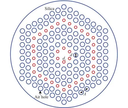
Fig. 1. Schematic cross section of the proposed HN-HF.
3.Numerical Method
The full vector finite difference method with anisotropic perfectly matched layers is used to calculate the different properties of the proposed HN-HF. The effective refractive index nefffor a given wavelength can be obtained by solving the eigen value problem from Maxwell equation. The real part of the complex effective refractive index is used to calculate the chromatic dispersion and the imaginary part of the complex effective refractive index is used to calculate the confinement loss of the proposed HN-HF. The material dispersion given by Sellmeier equation is directly included in the calculation.Therefore, in this calculation, the chromatic dispersion corresponds to the total dispersion of the proposed HN-HF[6].The chromatic dispersion, chromatic dispersion slope,confinement loss, effective area, and nonlinear coefficient γ are calculated by the following equations[6],[17]:
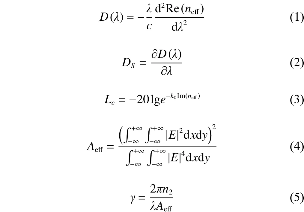
where, neffis the complex effective index, Re(neff) is the real part of the complex effective index, Im(neff) is the imaginary part of the complex refractive index, k0is the free space wave number, λ is the operating wavelength, c is the velocity of light in a vacuum, E is the electric field, and n2is the nonlinear refractive index coefficient in the nonlinear part of the refractive index.
4.Results and Discussion
Fig. 2 represents the chromatic dispersion and chromatic dispersion slope properties for the proposed HN-HF in Fig. 1.From Fig. 2, it is observed that the HN-HF possesses ultraflattened chromatic dispersion from 1.0 μm to 1.7 μm wavelength range where d1=0.31 μm, d=0.77 μm, and Λ=0.87 μm. The ultra-flattened chromatic dispersion of about 0±9.0 ps/(nm·km) is obtained in the wavelength range of 1.0 μm to 1.7 μm. A small chromatic dispersion slope of less than ±0.06 ps/(nm2·km) can be seen from 1.0 μm to 1.7 μm wavelength range with d1=0.31 μm, d=0.77 μm, and Λ=0.87 μm as shown in Fig. 2.
Fig. 3 depicts the effective area and nonlinear coefficient properties for the proposed HN-HF in Fig. 1. From Fig. 3, it is observed that the HN-HF possesses small effective areas from 1.0 μm to 1.7 μm wavelength range where d1=0.31 μm,d=0.77 μm, and Λ=0.87 μm, which are 1.82 μm2at 1.06 μm,2.15 μm2at 1.31 μm, and 2.44 μm2at 1.55 μm, smaller than that of conventional fibers (about 86 μm2at 1.55 μm).Moreover, large nonlinear coefficients have been realized ranging from 1.0 μm to 1.7 μm with d1=0.31 μm, d=0.77 μm,and Λ=0.87 μm. Obviously, the proposed HN-HF has the nonlinear coefficients of more than 105 W−1km−1at 1.06 μm, 71 W−1km−1at 1.31 μm, and 53 W−1km−1at 1.55 μm which are higher than those reported ones[2]-[6].
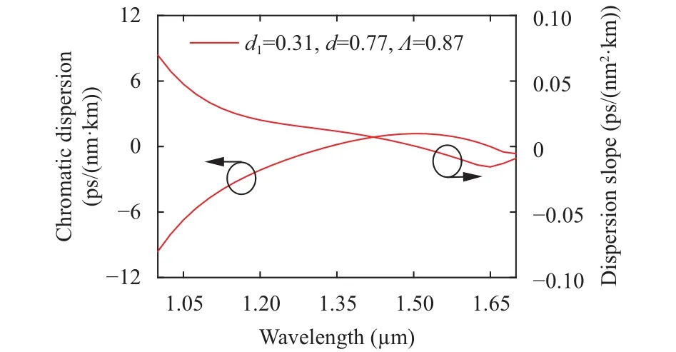
Fig. 2. Chromatic dispersion and chromatic dispersion slope of the proposed HN-HF as a function of wavelength.
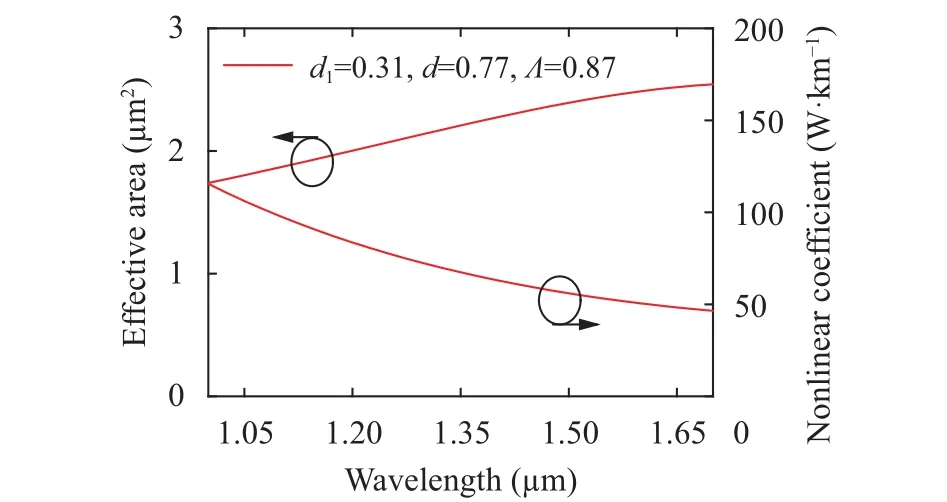
Fig. 3. Effective area and nonlinear coefficient of the proposed HN-HF as a function of wavelength.
Fig. 4 shows the confinement loss property of the proposed HN-HF in Fig. 1. The confinement loss is less than 10–6dB/km at the wavelength range of 1.0 μm to 1.7 μm. From the numerical simulation result, it has been seen that the confinement loss is achieved with less than 0.2 dB/km for the proposed HN-HFs.
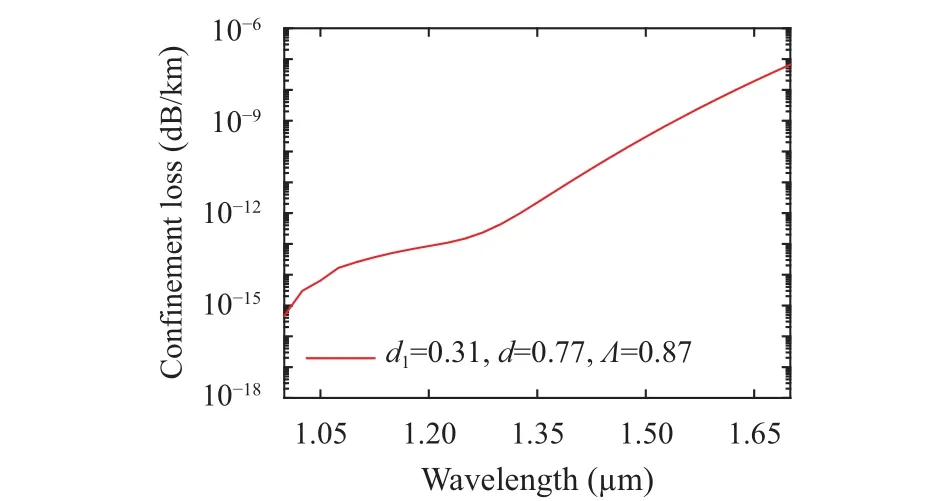
Fig. 4. Confinement loss of the proposed HN-HF as a function of wavelength.
Figs. 5 (a), (b), and (c) show the wavelength dependent SC spectrum intensity of the proposed high power HN-HF for the parameters Λ=0.87 μm, d1=0.31 μm, and d=0.77 μm at center wavelengths of 1.06 μm, 1.31 μm, and 1.55 μm, respectively.The nonlinear Schrödinger equation (NLSE) is used for numerical calculation of SC spectra[17]-[19]. The NLSE is solved by split-step Fourier method. The SC generation in the proposed high power HN-HF is numerically calculated at 1.06 μm, 1.31 μm, and 1.55 μm center wavelengths which is shown in Figs. 5 (a), (b), and (c), respectively. In Fig. 5,consider the propagation of the sech2waveform with the full width at half maximum (FWHM) TFWHMof 2.5 ps and Raman scattering parameter TRof 3.0 fs through the proposed high power HN-HF. The propagation constants around the carrier frequencies β2and β3used in the calculation for Fig. 5 are shown in Table 1 at different center wavelengths. From Fig. 5(a), it can be seen that the spectrum range is acquired from about 970 nm to 1170 nm at the center wavelength of 1.06 μm.The range of spectrum is obtained about 1175 nm to 1480 nm with the center wavelength at 1.31 μm, as depicted in Fig. 5(b). Moreover, Fig. 5 (c) shows that the spectrum range is acquired from about 1360 nm to 1800 nm when the center wavelength is set at 1.55 μm. After numerical simulation, the incident pulse input power Pinand fiber length LFare obtained which are also shown in Table 1. The power of 2.0 kW,3.0 kW, and 4.0 kW are achieved at the center wavelengths of 1.06 μm, 1.31 μm, and 1.55 μm, respectively. The required fiber length LFis 1 m for all the center wavelengths.
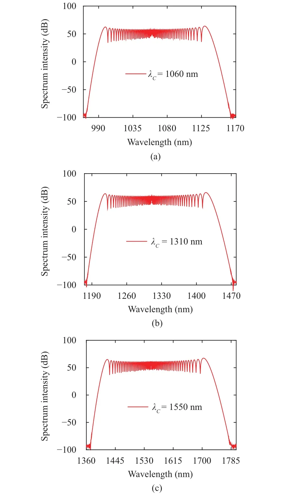
Fig. 5. Spectrum intensity of the proposed high power HN-HF at:(a) 1060 nm, (b) 1310 nm, and (c) 1550 nm.

Table 1: Fiber parameters
A power comparison has been made between the proposed fiber and that proposed in some other journals, which is shown in Table 2. From Table 2, it should be pointed out that the proposed fiber can achieve higher power values than those of reported papers[7]-[16],[18],[19].
The proposed HN-HF with ultraflattened chromatic dispersion, small chromatic dispersion slope, very low confinement loss, small effective area, high nonlinear coefficient, and high power SC spectrum output is applicable in high speed optical communications systems and medical applications.
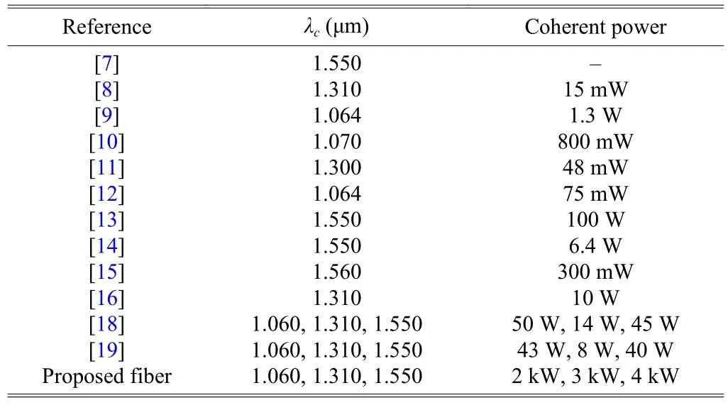
Table 2: Power comparison
5.Conclusions
It has been found that the proposed HN-HF has a high nonlinear coefficient with ultra-flattened chromatic dispersion and extremely low confinement loss in the wavelength range of 1.0 μm to 1.7 μm. Moreover, it has been observed that this proposed high power HN-HF could generate a broad SC spectrum with high power of 2.0 kW, 3.0 kW, and 4.0 kW at center wavelengths of 1.06 μm, 1.31 μm, and 1.55 μm,respectively. The proposed HN-HF may be suitable for optical communications and the applications of supercontinuum including medical imaging, tunable wavelength conversion, and optical studies of photonic devices.
[1]W. H. Reeves, J. C. Knight, and P. St. J. Russell,“Demonstration of ultra-flattened dispersion in photonic crystal fibers,”Optics Express, vol. 10, no. 14, pp. 609-613,2002.
[2]R. Hao and G. Sun, “Design of photonic crystal fiber with large negative dispersion and high nonlinearity,”Optik—Intl.Journal for Light and Electron Optics, vol. 126, no. 22, pp.3353-3356, 2015.
[3]J. Liao, J. Sun, Y. Qin, and M. Du, “Ultra flattened chromatic dispersion and highly nonlinear photonic crystal fibers with ultralow confinement loss employing hybrid cladding,”Optical Fiber Technology, vol. 19, no. 5, pp. 468-475, 2013.
[4]H. Xu, J. Wu, K. Xu, Y. Dai, and J. Lin, “Highly nonlinear all solid photonic crystal fibers with low dispersion slope,”Chinese Journal of Lasers, vol. 51, no. 8, pp. 1021-1027,2012.
[5]S. Matloub, R. Ejlali, and A. Rostami, “Highly nonlinear and near zero ultra-flattened dispersion dodecagonal photonic crystal fibers,”Progress in Electromagnetics Research C,vol. 60, pp. 115-123, Dec. 2015.
[6]F. Begum, Y. Namihira, S. M. A. Razzak, S. Kaijage, N. H.Hai, and N. Zou, “Highly nonlinear dispersion-flattened square photonic crystal fiber with low confinement losses,”Optical Review, vol. 14, no. 3, pp. 120-124, 2007.
[7]K. Saitoh, M. Koshiba, T. Hasegawa, and E. Sasaoka,“Highly nonlinear dispersion-flattened photonic crystal fibers for supercontinuum generation in a telecommunication window,”Optics Express, vol. 11, no. 10, pp. 843-852, 2004.
[8]H. Shibata, N. Ozaki, T. Yasuda,et al., “Imaging of spectraldomain optical coherence tomography using a superluminescent diode based on InAs quantum dots emitting broadband spectrum with Gaussian-like shape,”Japanese Journal of Applied Physics, vol. 54, no. 4S, pp.04DG07:1-5, 2015.
[9]T. Calmano, J. Siebenmorgen, O. Hellmig, K. Petermann,and G. Huber, “Nd:YAG waveguide laser with 1.3 W output power, fabricated by direct femtosecond laser writing,”Applied Physics B, vol. 100, no. 1, pp. 131-135, 2010.
[10]A. Zaytsev, C.-H. Lin, Y.-J. You, C.-C. Chung, C.-L. Wang,and C.-L. Pan, “Supercontinuum generation by noise-like pulses transmitted through normally dispersive standard single-mode fibers,”Optics Express, vol. 21, no. 13, pp.16056-16062, 2013.
[11]A. D. Aguirre, N. Nishizawa, J. G. Fujimoto, W. Seitz, M.Lederer, and D. Kopf, “Continuum generation in a novel photonic crystal fiber for ultrahigh resolution optical coherence tomography at 800 nm and 1300 nm,”Optics Express, vol. 14, no. 3, pp. 1145-1160, 2006.
[12]C. Louot, B. M. Shalaby, E. Capitaine,et al.,“Supercontinuum generation in an ytterbium-doped photonic crystal fiber for CARS spectroscopy,”IEEE Photonics Technology Letters, vol. 28, no. 19, pp. 2011-2014, 2016.
[13]G. J. Raj, R. V. J. Raja, N. Nagarajan, and G. Ramanathan,“Tunable broadband spectrum under the influence of temperature in IR region using CS2core photonic crystal fiber,”Journal of Lightwave Technology, vol. 34, no. 15, pp.3503-3509, 2016.
[14]D. Jain, R. Sidharthan, P. M. Moselund, S. Yoo, D. Ho, and O. Bang, “Record power, ultra-broadband supercontinuum source based on highly GeO2doped silica fiber,”Optics Express, vol. 24, no. 23, pp. 26667-26677, 2016.
[15]M. A. G. Porcel, F. Schepers, J. P. Epping,et al., “Twooctave spanning supercontinuum generation in stoichiometric silicon nitride waveguides pumped at telecom wavelengths,”Optics Express, vol. 25, no. 2, pp. 1542-1554, 2017.
[16]Y. Namihira, M. A. Hossain, T. Koga,et al., “Design of highly nonlinear dispersion flattened hexagonal photonic crystal fibers for dental optical coherence tomography applications,”Optical Review, vol. 19, no. 2, pp. 78-81,2012.
[17]G. Agrawal,Nonlinear Fiber Optics, 2nd ed. New York:Academic Press, 1995, pp. 195-211.
[18]F. Begum, Y. Namihira, T. Kinjo, and S. Kaijage,“Broadband supercontinuum spectrum generated highly nonlinear photonic crystal fiber applicable to medical and optical communication systems,”Japanese Journal of Applied Physics, vol. 50, no. 50, pp. 092502-092507, 2011.
[19]F. Begum and Y. Namihira, “Design of supercontinuum generating photonic crystal fiber at 1.06, 1.31 and 1.55 μm wavelengths for medical imaging and optical transmission systems,”Natural Science, vol. 3, no. 5, pp. 401-407, 2011.
 Journal of Electronic Science and Technology2018年1期
- Journal of Electronic Science and Technology的其它文章
- Message from JEST Editorial Committee
- Modeling TCP Incast Issue in Data Center Networks and an Adaptive Application-Layer Solution
- UEs Power Reduction Evolution with Adaptive Mechanism over LTE Wireless Networks
- Multi-Reconfigurable Band-Notched Coplanar Waveguide-Fed Slot Antenna
- Overview of Graphene as Anode in Lithium-Ion Batteries
- Pairing-Free Certificateless Key-Insulated Encryption with Provable Security
