Study on Dynamic Response of Cargo Hold Structure of CNG Carriers under Gas Explosion Loading
GUAN Yi-feng,FANG Shan-zhao,ZHAO Shi-chao,SHI Teng-fei,DONG Yuan-chao
(1.School of Naval Architecture&Ocean Engineering,Jiangsu University of Science and Technology,Zhenjiang 212003,China;2.Zhejiang Province Port Management Office,Haiyan 314300,China;3.China Institute of Marine Technology&Economy,Beijing 100081,China)
0 Introduction
Natural gas is a kind of environment-keeping and economical efficient clean energy.Promoting the application of natural gas widely has become China’s important energy strategy.With the increasing demand for natural gas,the high cost of natural gas transportation has restricted the extraction and use of natural gas.Nowadays,liquefied natural gas(LNG)is a widely used method for the transportation of natural gas.LNG carriers will expose a number of drawbacks due to the huge investment in piping equipment,liquefied-gasification equipment and supporting facilities,such as natural gas transport between two adjacent islands.A new and more efficient mode of transport is a main problem to be solved urgently in the case of short-distance transport and special conditions.CNG carriers provide a viable option for such natural gas transport to fill some of the market blind areas where LNG transport is not economical.It is therefore clear that the CNG carrier as a supplement to other forms of natural gas transportation has a very broad market prospects[1].However,CNG carriers are likely to cause natural gas leakage and explosion during transportation due to vibration or total longitudinal bending or other reasons.In order to ensure the safety of the ship and improve the vitality of the ship,this paper has carried out the research on the dynamic response of the cargo hold structure under the action of the gas explosion load on the basis of the world’s first compressed natural gas carrier.
1 Overview of CNG carriers
This compressed natural gas carrier,built by Jiangsu HT Shipyard,is the world’s first commercial CNG carrier,and it belongs to the ABS and BKI double classes.This carrier loaded 832 high pressure cylinders totally,including 40 bottles as the main engine fuel.The cylinders are fixed in five cargo holds.92 cylinders are located in the first cargo hold,200 cylinders in the second cargo hold,204 cylinders in the third cargo hold,204 cylinders in the fourth cargo hold,and 132 cylinders in the fifth cargo hold.All the cylinders are arranged in a vertical direction.The working pressure of the cylinder is 25 MPa and the gas loading and unloading temperature is maintained within 38℃.The ship is of longitudinal framing system,with 110 meters in length,17.6 meters in breadth,9 meters in depth and with a capacity of 18 crew members.Fig.1 shows the general layout of the CNG carriers and Fig.2 shows the schematic arrangement of cylinders.
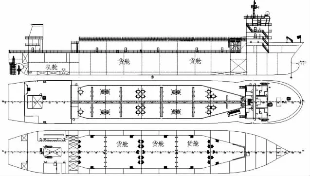
Fig.1 The general layout of the CNG carriers

Fig.2 Schematic arrangement of cylinders
2 Basic equations and solving methods
The propagation of the ideal gas explosion blast wave is expressed by the three-dimen-sional Euler equation of motion[2]:
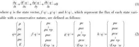
where ρ is the mass density of the material,u,v and w are the three components of the velocity vector,p represents pressure,E represents system total energy.
3 Finite element model and parameter definition
In this paper,the third hold(FR83-FR105)is selected for the finite element model.Because the third compartment is in the middle of the ship,larger total longitudinal bending stress may arise,and the relative structure displacement is more likely to occur.This may cause the cylinder seatings fatigue and valve connection loose and other adverse phenomena.The finite element software PATRAN is used to build the finite element model according to the design drawing.The ship is of double bottom,double side,and longitudinal framing arrangement.The cargo holds are loaded with 204 high pressure cylinders.The finite element model is shown in Fig.3.
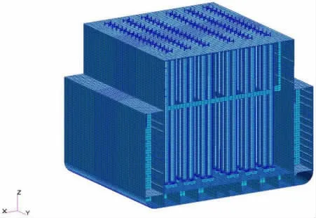
Fig.3 Finite element model of cargo hold structure
The general strength of marine steel(B-class steel)is used for cargo hold structure and elastic-plastic mode for material is used.Specific material parameters are as follows,material density ρ=7 800 kg/m3;elastic modulus E=210 MPa;yield stress σY=235 MPa(Quasi-static yield stress);Poisson’s ratio υ=0.3;dynamic failure strain δ=0.15,the cylinder quasi-static pressure of the high-strength steels with heat treatment can reach to 670 MPa.
γ law equation is used for air inside and outside the hold.P=(γ- )1 ρe,here e is internal energy of unit mass, ρ is overall material density,and γ is specific heat ratio.Because the ROE algorithm does not support the JWL state equation,the TNT state description use the same state equation[3-4]with explosive source density ρ=36 kg/m3and internal energy of explosive source e=2.76×10⁶J/kg.
4 The determination of risk source,source location and leakage amount
4.1 Risk source
CNG carrier has a high demand on the quality of the cylinder,the choice of the cylinder to be manufactured through a rigorous heat treatment,with good toughness and anti-cracking performance.Therefore the gas bottle leakage probability can be negligible.Affected by factors like cylinder sealing and the hull overall longitudinal bending and vibration,the leakage positions are most likely to appear in the upper and bottom positions of the cylinder.Therefore,the crew on board should ensure that the gas detection system for cargo hold is sensitive and reliable.The leakage caused by cracks can be immediately found and timely measures can be taken to avoid hazardous accidents.

Fig.4 Diagram of apt-to-leak position
4.2 Explosion source location
Because the explosion source position is uncertain and the density of leaking gas is often smaller than that of the air,the leaking gas will rise to the top of the hold.So three typical and more dangerous explosion positions near the top plate in the hold are chosen in the paper.Position 1(See Fig.5)is located at FR 94 which is 1 m away from the top plate and the cover side plate;Position 2(See Fig.6)is located in the longitudinal middle section of the FR 94,which is 1 m away from the top plate;Position 3(See Fig.7)is located at FR 103,which is 1 m away from the from the transverse bulkhead and top plate and cover side plate.The 1-meterspacing is designed by considering the structural space layout and the more accurate principle of using TNT equivalent method to simulate the gas field explosion far field[5].
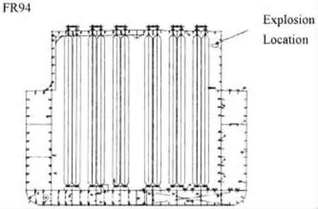
Fig.5 Location 1 schematic diagram

Fig.6 Location 2 schematic diagram

Fig.7 Location 3 schematic diagram
4.3 Leakage amount
According to the high-pressure cylinder hold leak assessment test by the system designer,the reasons for the greater possibility of the leakage of gas inside the hold are due to the leakage of the lower end sealing of the cylinder and the leakage of the upper end sealing of the cylinder.204 risk points are selected for testing by the system designer,and the test results show that the rate of leakage is low.This paper uses the equivalent TNT method proposed by Japanese scholar Emi Hirohiko[6].The basic concept of the TNT equivalent model is based on the dimension analysis.According to the principle of energy equivalent,the shock wave generated by the combustible gas cloud is equivalent to the wave generated by the same energy TNT explosion,and then the intensity of gas cloud explosion is predicted by the results and regular pattern of TNT explosion.According to the equivalent TNT method,the equivalent TNT mass of the leaking gas can be expressed as:

where WTNTis the TNT equivalent of gas cloud,α is TNT equivalent efficiency(generally 4%),Wfis the total mass of combustible gas cloud,the density of combustible gas cloud is 1.123 kg/m3;Qfis the explosion heat of combustible gas cloud(39 MJ/kg);QTNTis TNT explosion heat(4.5 MJ/kg).According to the data provided by the system designer,the leakage rate is about 8 m3/h-9.5 m3/h,and the detection time of the leaked gas detection device is 6-9 min.For the sake of security,this paper takes the leakage rate of 10 m3/h,leakage time of 9 minutes,calculated leakage amount is 1.5 m3.Natural gas may explode when the concentration range from 5%to 15%,the explosion power reaches its maximum degree when the concentration is 9.5%.In this paper,air and 9.5%concentration of the natural gas are fully mixed together and are taken as an explosion condition in the hold.According to the TNT equivalent method,the gas cloud energy is converted to TNT energy of 6.15 kg.
5 Calculation analysis
Modeling and calculation are done by using MSC.PATRAN/DYTRAN software,which is a large general-purpose three-dimensional finite element program for analyzing highly nonlinear and transient dynamic responses.Numerical simulation of high-speed transient nonlinear dynamic problem and transient fluid-solid coupling problem can be simulated well by the software.For the problem of gas explosion,the high order approximation method in this software solver has higher accuracy.In addition,the general coupling method of MSC.DYTRAN is more suitable for all fluid-solid coupling problems.
5.1 Structural stress and deformation analysis

Fig.8 Position 1

Fig.9 Position 2

Fig.10 Position 3

Tab.1 Stress and deformation table for different working conditions
From the calculation results above(Tab.1),it can be known that the maximum stress of 367 MPa appears on the cover side plate stiffener and the maximum displacement is 40.4 mm on the transverse bulkhead when the explosion source is located near the side (position 1).The maximum stress of 255 MPa appears on the cover side plate stiffener and the maximum displacement is 28.4 mm on the top plate when the explosion source is located near the middle(position 2).The maximum stress of 397 MPa appears on the cover side plate stiffener and the transverse bulkhead stiffener and the maximum displacement of 57.6 mm appears on the transverse bulkhead when the explosion source is located near the corner(position 3).But it is also found that some of the maximum stresses in the calculations have gone beyond the quasi-static stresses of the structure.This is mainly due to the consideration of the strain rate sensitivity of the material,leading to a stronger structure stiffness within a certain range when the structure is subject to instantaneous impact.Compared with the above three conditions,it is found that when the source is located near the corner(position 3),the structural stress and deformation are generally greater than the other two conditions in terms of stress or deformation.
5.2 Analysis of structure energy absorption
Comparing the above three kinds of explosion conditions with the structure energy absorption,when explosion source is located near the side(position 1),the total energy absorption is 64 753.63 J.Top plate,top plate stiffeners,cover side plate and top plate beams absorb more energy;their energy absorption is 6 257 J,10 503 J,12 267 J and 17 266 J,respectively,accounting for 9.68%,16.37%,18.94%and 26.66%of the total energy absorption.The sum of the four structures’absorption accounts for 71.65%of the total energy absorption.When the explosion source is located near the middle(position 2),the total absorption is 23 254.38 J.The top plate,top plate stiffeners,cover side plate,top plate beams absorb more energy;the energy absorption is 3 556.50 J,3 742 J,3 615.80 J and 7 018.40 J,respectively,accounting for 15.29%,16.09%,15.55%and 30.18%of the total energy absorption.The sum of the four structures’absorption accounts for 77.11%of the total energy.When the source is located near the corner(position 3),the total energy absorption is 108 244.90 J.Cover side plate stiffeners,transverse bulkhead stiffeners,transverse bulkheads,top plate stiffeners,cover side plate and top plate beams absorb more energy;the energy absorption is 17 102 J,12 362 J,22 875 J,19 545 J,14 603 J and 13 088 J,respectively,accounting for 15.80%,11.42%,21.13%,18.06%,13.49%and 12.09%of the total energy absorption.The sum of these six structures’absorption accounts for 91.99%of the total energy.
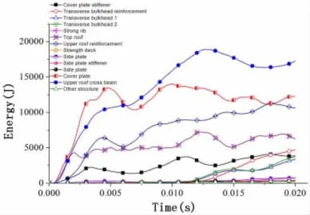
Fig.11 Position 1

Fig.12 Position 2
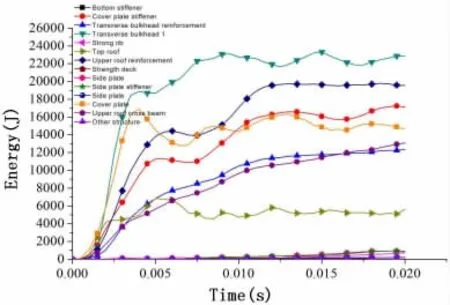
Fig.13 Position 3
6 Strengthening scheme analysis
6.1 Strengthening scheme
Under special conditions,the hull structure strength is weak.Now the hull structure is strengthened to improve the anti-blast performance of the structure.In view of dangerous explosion conditions in the hold(position 3),plate thickness increase,stiffener thickness increase and the addition of stiffener quantity on the plate are carried out in different ways.In order to study the dynamic response of the cargo hold structure of different reinforcement schemes,the following three strengthening schemes are chosen,as shown in Tab.2 and Figs.14-15.

Fig.14 Scheme diagram for strengthening

Tab.2 Different strengthening scheme
6.2 Deformation analysis
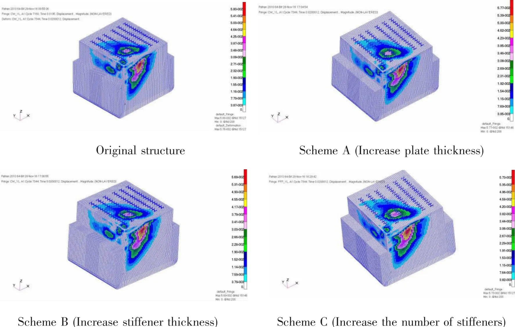
Fig.15 Structure deformation images
After analyzing the deformation of the original structure,scheme A(Increase plate thickness),scheme B(Increase stiffener thickness)and scheme C(Increase the number of stiffeners),the above cargo hold structure variables show that under the same explosion conditions,the structures with different strengthening measures have different deformations.The largest deformation of structure is all located in the transverse bulkhead.The maximum deformation of the original structure is 62 mm.In scheme A,the top plate,transverse bulkhead upper area,and cover side plate upper area are increased by 1 mm to increase the local strength of the cargo hold structure;and the maximum deformation of the structure is 56 mm.In scheme B,the thickness of the plate is kept unchanged;and the thickness of top plate stiffeners and the transverse bulkhead upper stiffeners and cover side plate upper stiffeners are increased by 2 mm to increase the rigidity of the cargo hold structure.Deformation of the structure is larger than that of scheme A,and the maximum deformation is 56.9 mm.In scheme C,the thickness of the original plate and the thickness of stiffeners on plate are kept unchanged;the number of stiffeners on the top plate,and transverse bulkhead upper area and cover side plate upper area is increased.Four(4)320×7 stiffeners on the top plate,three(3)320×7 stiffeners on transverse bulkheads upper area,and four(4)320×7 stiffeners on cover side plate upper area are increased.These measures are taken to restrain cargo hold structure deformation.In scheme C,the deformation of the structure is larger than that of the scheme A,and the maximum deformation is 57.5 mm.Comparing with original structure deformation,the deformation in schemes A,B and C is decreased by 9.7%,8.2%and 7.2%,respectively.Therefore,scheme A is the most effective solution for reducing structural deformation.
6.3 Stress analysis
In order to better observe the stress distribution of the improved structure,Fig.16 shows the final stress cloud diagram of the original structure and three reinforcement structures under the explosion condition.Based on the analysis of the dynamic response of the cargo hold structure of the compressed natural gas carrier,it is found that the deformation under the action of the gas explosion shock wave is localized;the stress is mainly concentrated in the top plate structure,transverse bulkhead,and cover side plate.Considering the strain rate sensitivity of the material,the maximum stresses in schemes A,B,C are not much different compared with the original structure,with maximum stress being 350 MPa.And the maximum stress values of scheme A,scheme B and scheme C are 337 MPa,352 MPa and 350 MPa,respectively.Therefore,scheme A is the most effective solution for reducing structural stress.

Fig.16 Stress images
6.4 Comparison of energy absorption

Fig.17 Structural deformation energy absorption curve

Tab.3 Different scheme of structure energy absorption
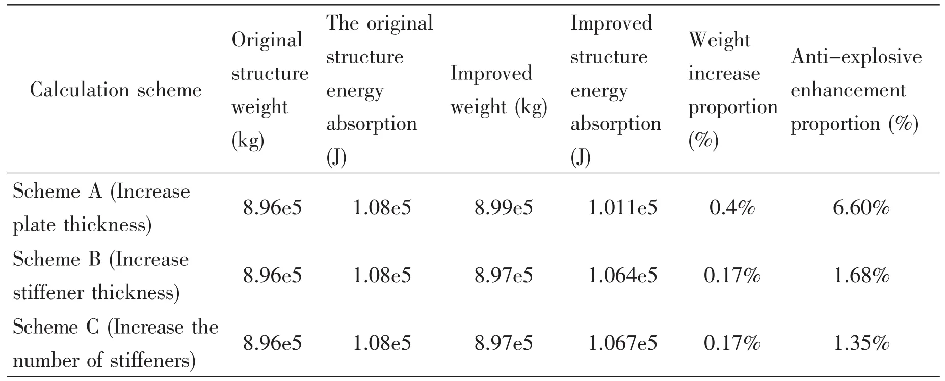
Tab.4 Comparison of anti-blast performance
It can be seen from Fig.17 and Tabs.3-4,the improved structure weight has increased,but the increased amount is not significant.The increased weight of scheme A(Increase plate thickness),scheme B(Increase stiffener thickness)and scheme C(Increase the number of stiffeners)accounts for 0.4%,0.17%and 0.17%of the weight of original structure respectively;but the proportion of increased weight is very small.From the point of view of structural deformation energy absorption,the anti-blast performance of the three schemes is increased by 6.60%,1.68%and 1.35%,respectively.After comparative analysis,scheme A is the best solution to enhance the anti-blast performance.
7 Conclusions
(1)For the world’s first cargo ship for compressed natural gas,the gas source leakage risk,leakage location and leakage amount are analyzed.
(2)The most dangerous explosion condition,due to gas leaks in the cargo hold,is obtained by numerical simulation.
(3)In response to the three strengthened schemes,from the structural deformation,stress and energy absorption point of view,scheme A(increase the thickness of the plate)is the best solution to enhance the anti-blast performance.
[1]Shi Tengfei,Guan Yifeng,Fang Shanzhao.Gas leakage risk analysis in the loading and unloading process of CNG carrier[J].Ship&Ocean Engineering,2016(A01):60-65.
[2]MSC.DYTRAN theory manual[K].MSC Software Corporation,2004.
[3]Kivity Y,Feller S.Blast venting from a cubicle[C].The 22nd DOD Explosives Safety Seminar,1986:1-19.
[4]Kivity Y,Florie C,Lenselink H.Response of protective structures to internal explosions with blast venting[C].MSC World Users’Conference,1993:1-10.
[5]Ding Yun,Ding Dayu,Tang Mingjun.Numerical calculation of explosive wave in non-ideal explosion source[J].Explosion and Shock Waves,1995,15(4):289-299.
[6]Emi Hirohiko.Study on the safety of liquid gas[C].Japanese Shipbuilding Society Proceedings,1984.
- 船舶力学的其它文章
- Study on Vibration Characteristic of Jacket Platform Considering the Structure-Pile-Fluid-Soil Interaction
- Efficient Simulation of the Slamming Loads Using the Hybrid Two-Step Solution
- Simulation of Brittle-Ice Contacting with Stiffened Plate with Peridynamics
- Low-Cycle Fatigue Crack-Propagation Behavior of Ship Cracked Plate Considering the Accumulative Plasticity under Variable Amplitude Loading
- Investigations on the Mechanical Behavior of an Innovative Subsurface Tension Leg Platform in Ultra-Deep Water(Part I)
- LES Simulations of the Flow Around a Propeller in Crash Back and Crash Ahead

