
Low-Cycle Fatigue Crack-Propagation Behavior of Ship Cracked Plate Considering the Accumulative Plasticity under Variable Amplitude Loading
2018-03-28 12:30:23DENGJunlinYANGPingMALiQIANWei
船舶力学 2018年3期
DENG Jun-lin,YANG Ping,MA Li,QIAN Wei
(1a.Key Laboratory of High Performance Ship Technology(Wuhan University of Technology),Ministry of Education,Wuhan 430063,China;1b.Wuhan University of Technology,Wuhan 430063,China;2.Department of Naval Architecture&Ocean Engineering,Qinzhou University,Guangxi 535000,China)
0 Introduction
For many fatigue-critical parts of structures,vehicles,ship and machines,the fatigue crack propagation under service conditions generally involves random or variable amplitude,rather than constant amplitude loading conditions[1].The significant retardation or acceleration effect in fatigue crack propagation may occur as a result of the tensile/compression overload variations[2-3],where the variation of load size and load order has an important influence on the fa-tigue crack growth rate.In addition,the research results have revealed that the most overall fractures of ship hulls tend to be the coupling interaction result of low-cycle fatigue and incremental accumulative plastic failure[4-5].The actual ship hull structure under service loading may suffer from low-cycle fatigue damage,when the accumulative plastic deformation of the ship hull structures exceeds a certain value,it will lead to the initiation and expansion of the low-cycle fatigue crack of the local region of the ship hull structures,and finally until the structural failure.Therefore,it is of great practical significance to analyze the low-cycle fatigue crack growth life of ship hull under variable amplitude loading,and an accurate prediction of fatigue life requires an adequate evaluation of these load interaction effects.
The effects of single peak tensile overloads have been reported in many investigations[6-10]simply because this type of loading can lead to significant load interaction effects.As one of the most common forms of variable amplitude loading,the low-cycle fatigue crack propagation under tensile overload has been extensively studied[6].The significant retardation effect in fatigue crack propagation may occur under the tensile overload variations.Many factors influence the retardation effect,where the most significant one is the overload ratio ROL=σOL/σmax.In addition,several mechanisms have been proposed to explain crack growth retardation,which include models based on residual stress[7],crack closure[8],crack tip blunting[9]and strain hardening[10].In spite of some controversy,the effect of residual plastic deformation,which leads to compressive stresses before the crack tip and raises the crack opening load on subsequent crack growth(crack closure),has been identified as the most important aspect in explaining the variation of the characteristic features of post-overload transients[7-10].
Compared with the studies on the retardation effect of single peak tensile overload in fatigue crack propagation,the research on the acceleration effects of single peak compressive overload in fatigue crack propagation is relatively much fewer.Some researchers[11]pointed out that the compressive overload will cause the acceleration effects in fatigue crack propagation;Skorupa[12]pointed out that the compressive overload effect on fatigue crack propagation depended on the material and load parameters.In addition,based on the critical distance theory,Zheng[13]has proposed a numerical model based on the theory of critical distances to simulate the fatigue crack propagation of cast aluminum alloys under tensile/compressive overload.The accumulated plastic energy density at the critical distance point ahead of the crack tip is used as a measure of the fatigue damage.
The low-cycle fatigue crack propagation is mainly in the plastic zone,where the stress field at the crack tip is quite complex.So the classical predicted model of fatigue crack propagation based on linear elastic mechanics is difficult to apply.Additionally,Yao and Kang,et al[14-15]have pointed out that the influence of accumulative incremental plasticity should be considered in the study of the low-cycle fatigue life of ship structures.The accumulative plastic deformation which will produce additional damage and reduce the low-cycle fatigue life of the hull structure is produced at the crack tip.Therefore,the low-cycle fatigue crack growth life analysis method of considering the accumulative damage at crack tip is more realistic to evaluate the overall fracture load bearing capacity of the ship hull plate members.Accordingly,the accumulative plastic deformation at crack tip decreases structure material stiffness on the crack tip plastic zone,then exacerbates the ductility loss of structure material in the crack tip plastic zone and causes the fatigue damage of the crack tip by large scale yielding under low-cycle fatigue loading.
Therefore,it is necessary to analyze the low-cycle fatigue crack propagation of cracked plate under the variable amplitude loading based on the accumulative plasticity in the vicinity of crack tip.As mentioned above,this study based on the cyclic stress-strain field of crack tip,continues to use the prediction model proposed in previous study[1]to evaluate the low-cycle fatigue crack growth of cracked plate under the tensile/compressive overload of the variable amplitude low-cyclic fatigue loading,considering the effect of the accumulative plastic deformation of crack tip.
1 Prediction model of low-cycle fatigue crack growth
In this study,the low-cycle fatigue crack growth behavior of cracked plate under variable amplitude loading is studied based on the proposed model in the previous study[1].The maximum plastic zone radius and the cyclic plastic zone radius at crack tip under variable amplitude loading are shown in Eq.(1);If the maximum stress intensity factor (Kmax)and the stress intensity factor()K at the crack tip are known,the cycle plastic zone radius and the maximum plastic zone radius can be expressed as follows[16]:

Fig.1 shows that the plate element structure in the monotonic plastic zone at the crack tip is composed of a series of micro fatigue unit δρ.The amount of the fatigue damage for micro fatigue units δρ in the monotonic plastic zone at the crack tip caused by each cycle load is about 1/Ni.After n time cycles,the total amount of the fatigue damage crack tip for micro fatigue units δρ in the cycle plastic zone at the crack tip is up toWhen the accumulative fatigue damage D for micro fatigue units δρ in the monotonic plastic zone at the crack tip reaches the critical value of D0,the crack tip extends a plastic zone size.So the accumulative fatigue damage for micro fatigue units δρ in the monotonic plastic zone is calculated by each fatigue unit under variable amplitudes loading.

Fig.1 The element model in front of crack tip
The current crack length aican be considered as a function of the initial crack size a0,the numbers of damaged fatigue units naand the width of the residual ligament at the crack tip of the current unit rl,as shown in Fig.1.

At the beginning of the low-cycle fatigue crack growth,the width of the residual ligament at the crack tip of the current unit rl=δρ,and the number of damaged fatigue units in the plastic zone near the crack tip na=0,So the current crack size is equal to the initial crack size ai=a0;at the same time,all the crack damage variables of fatigue unit at the initial time were zero.

According to Fig.1,when the accumulative damage of the ith fatigue units in the plastic zone at the crack tip is calculated,the distance rifrom the fatigue unit to the current crack tip under the variable amplitude low-cycle fatigue loading can be expressed as follows:
After obtained the distance expression ri,the Eq.(3)is substituted into the previous study[1]to solve the distribution of the stress-strain field at the crack tip and the amount of fatigue damage under the ith fatigue cycle load.In the Eq.(3),the width of the residual ligament at the crack tip of the current fatigue unit rl can be obtained through the linear interpolation of the damage parameters of the front and rear boundary of the ith fatigue unit in the monotonic plastic zone at the crack tip,which is expressed as below:

The Eqs.(2)and(3)are substituted into the previous study[1],which have obtained the stress-strain field and the fatigue damage of the crack tip under constant fatigue load,to solve respectively the distribution of the stress-strain field at the crack tip and the amount of fatigue damage under variable amplitude fatigue loading.
The maximum plastic zone radius Eq.(1)under variable amplitude fatigue load is substitut-ed into the proposed model in the author’s previous study[1],which can be used to obtain the low-cycle fatigue crack propagation rate under variable amplitude low-cycle fatigue loading as follows:

The Eq.(5)is the predicted model for the low-cycle fatigue crack growth of cracked plate under variable amplitude low-cycle fatigue loading,which considered the effect of accumulative plastic deformation at crack tip.By using the proposed prediction model Eq.(5),the lowcycle fatigue crack growth rate of hull cracked plate is analyzed respectively under the single peak tensile/compressive overload of variable amplitude loading in this study.
2 Experimental investigations
2.1 Experimental setup
The fatigue crack growth experiments were made on 7 mm thick hull notch cracked plate specimens with other dimensions shown in Fig.2.The specimen and the test setup are shown in Fig.3.The steel Q235,is a low carbon steel which is widely used in hull structures,was employed to the tests,where the uniaxial tensile stress-strain curve of Q235 steel is obtained by tensile test as shown in Fig.4.And the basic material mechanics properties of Q235 steel are obtained by tensile test as shown in Tab.1.Chemical composition(in%wt)of this material is:C 0.18,Si 0.43,Mn 1.4,P 0.02,S 0.014 and V 0.13.The crack planes in the specimens were orientated perpendicular to the rolling direction of the plates.The fatigue crack growth experiments were performed in air and at room temperature using a computer controlled servohydraulic test machine,MTS322 250 kN.The crack length was simultaneously measured using strain extensometer with a 10 mm gauge length,±1 mm range,and 0.01%extensometer strain control accuracy whose operating temperature ranges from_80_C to 200_C,as shown in Fig.3.A uniaxial controlled load with maximum applied load was used to control the total stress range and a tensile-compression loading with a triangular waveform was used to ensure that the strain rate remained constant in a loop beginning with the tensile load.

Fig.2 A notch cracked plate specimen(notch diameter is 4.8 mm,thickness is 7mm)
A 0.25 Hz frequency was chosen based on other low-cycle fatigue test results available in the literature.The specimens were tested in cyclic loading,considered the influence of the compressive stress.The tests were conducted under constant amplitude loading with different stress ratios and mean stress to study the low-cycle fatigue crack growth.Each test was performed to failure and a mean of three measurements under each condition was taken.
The real-time information such as time,load,crack tip opening displacement and extensometer strain were recorded.After the fatigue failure,fractographs and microscopic changes were examined by using LEO Electron Microscopy 1530 VP field emission scanning electron microscope(FESEM)to analyze the failure mechanisms.An example of the fracture process and fracture morphologies of low-cycle fatigue crack propagation is shown in Fig.5.

Fig.3 Test setup diagram of notch cracked plate specimen

Fig.4 Tensile stress strain curve of Q235 steel

Tab.1 The mechanics properties of Q235
First by sticking to the crack tip strain we measured to get accumulative plastic deformation at the crack tip and the corresponding relationship between the deformation rate and the number of cycles under different stress ratio and mean stress and provide validation for the verification of the model;then by the scale line prefabricated on the initial crack tip and combined with distribution in the sample on the high times magnifying glass,we can observe and record a crack moving cycles of a tick spacing and obtain low-cycle fatigue crack growth rate curve.
By connecting the projector with the magnifying glass,it is clear that the position of the current crack tip can be obtained clearly and timely.When the fatigue load is stuck in the cyclic vale,the horizontal coordinate of the crack tip is recorded,and the crack length corresponding to the cycle can be obtained by subtracting the horizontal coordinate from the prior determination of the fatigue crack initiation and crack.The crack growth rate can be obtained by the increment of the crack length divided by the number of load cycles experienced by two adjacent crack measurements:

where ai+1and aiare measured value of two adjacent crack length.Crack propagation velocity calculated by Eq.(6)is mean velocity of extension from aito ai+1.ΔKeffalso uses the mean crack lengthof two measurements;specific calculation expressions can refer to Ref.[13].
The effective stress intensity factor range of the crack tip can be obtained by the following equation[13]:


2.2 Fracture morphology analysis
Fig.5 shows the fracture process and fracture morphology of low-cycle fatigue crack growth for specimen.It can be seen the obvious crack closure phenomenon in Fig.5(a),which is the crack morphology before overloading;the opening displacement at the crack tip increases obviously in Fig.5(b)after the overload,and the bifurcation can be emerged at crack tip,which caused two new crack tip.It is the morphology of a crack tip at unloading stage after applying an overload peak in Fig.5(c).It can not be seen the obvious crack closure in Fig.5(c),when the loading is unloaded to the minimum value;meanwhile,the acceleration effect can be produced at crack tip with the expansion of the low-cycle fatigue crack.It is the morphology of a crack tip expanded a short distance after overloading in Fig.5(d).Contrasted to Fig.5(a),the crack closure size caused by the tensile overload peak is larger than that by the constant loading in Fig.5(d).Moreover,the low-cycle fatigue crack growth continues to expand in the original expansion direction after the segregation occurred.The fracture morphology in the fatigue test showed transgranular fracture in Fig.5(e).It can be found that the accumulative plastic deformation was remarkably at the crack tip,and then the larger damage was produced in the process of cyclic loading,which led to the decrease of the ability to resist deformation for the material.With the increasing of stress ratio,the larger accumulative plastic deformation will lead to earlier failure.When the accumulative plastic deformation in front of crack tip is up to the critical value,the crack tip is gradually moved downward from a vertical scale to the next one with performance for the crack propagation.


Fig.5 Fracture process and fracture morphology of low-cycle fatigue crack growth
Therefore,it is necessary to consider the effect of accumulative incremental plastic damage at the Gauss integral point of the low-cycle fatigue crack tip in the study of the low-cycle fatigue crack growth rate of the cracked plate under asymmetrical stress cyclic loading.
2.3 Experimental result and discussion
According to the conventional mechanical properties and the material parameters of Q235 steel obtained from tests,the low-cycle fatigue crack growth rate of cracked plate under different low-cycle fatigue load is predicted by using the prediction model proposed in this study,and the analyzed results are finally compared with the experiment as follows:
2.3.1 Low-cycle fatigue crack growth rate under single peak tensile overloads
After the single peak tensile overload introduced into the constant amplitude low-cycle fatigue load,for the different stress ratios R,the mean stresses and tensile overload ratios OLR,the results of the comparison between the predicted value of the low-cycle fatigue crack growth rate used by the proposed model in this study and the experimental data are shown in Fig.6.
It has been shown in Fig.6 that the retardation effect of the low-cycle fatigue crack propagation occurs under the tensile overload.The larger the tensile overload ratio OLR is,the more obvious in the retardation effect of the low-cycle fatigue crack propagation of the cracked plate is with the constant stress ratio and mean stress,and the relatively lower of the minimum low-cycle fatigue crack growth rate in retardation stage is.The length of the retardation period of the low-cycle fatigue crack propagation is also longer.Alike,the larger the stress ratio R is,the more obvious in the retardation effect of the low-cycle fatigue crack propagation of the cracked plate is with the same tensile overload ratio OLR and mean stress,and the relatively lower of the minimum low-cycle fatigue crack growth rate in retardation stage also is.The mean stress has a similar influence on the retardation effect of the low-cycle fatigue crack growth of the ship with the tensile overload ratio.

Fig.6 Comparison results between the prediction and the experiment of low-cycle fatigue crack growth rate for different tensile overloads
The mechanism of the retardation effect on the low-cycle fatigue crack growth rate of cracked plate with tensile overload is explained as follows:According to the calculation results of residual stress with the tensile overload,the accumulation progressive plastic deformation of crack tip significantly increased,which caused the large residual compressive stress in the vicinity of crack tip.The residual compressive stress decreases the effective stress intensity factor range of the crack tip,which reduces the low-cycle fatigue crack growth rate,and then produces the retardation effect.When the crack tip gradually exceeds out the forward plastic zone of crack tip which induced by the single peak tensile overload,the residual stress at crack tip gradually disappear,so the low-cycle fatigue crack growth rate gradually recovers the level of the constant amplitude loading.According to the experiment and the finite element analysis,Jiang[17]pointed out that the increase of the fatigue crack opening stress after the tensile overload peak led to the decrease of the effective stress intensity factor range,which produced the retardation effect of the low-cycle fatigue crack growth.
2.3.2 Low-cycle fatigue crack growth under single peak compressive overload
After the single peak compressive overload introduced into the constant amplitude lowcycle fatigue load,for the different cases of the stress ratio R,the mean stress and compressive overload ratios ULR,the results of the comparison between the predicted value of the lowcycle fatigue crack growth rate used by the proposed model in this study and the experimental data are shown in Fig.7.

Fig.7 Comparison results between the prediction and the experiment of low-cycle fatigue crack growth rate for different compressive overloads
It has been shown in Fig.7 that the acceleration effect of the low-cycle fatigue crack propagation occurs under the compressive overload.The larger the compressive overload ratio ULR is,the more obvious in the acceleration effect of the low-cycle fatigue crack propagation of the cracked plate is with the constant stress ratio and mean stress,and the relatively lower of the minimum low-cycle fatigue crack growth rate in retardation stage is.The length of the acceleration stage of the low-cycle fatigue crack propagation is also longer.Alike,the larger the stress ratio R is,the more obvious in the acceleration effect of the low-cycle fatigue crack propagation of the cracked plate is with the same compressive overload ratio ULR and mean stress,and the relatively lower of the minimum low-cycle fatigue crack growth rate in retardation stage also is.The mean stress has a similar influence on the acceleration effect of the lowcycle fatigue crack growth of the ship with the compressive overload ratio.
The mechanism of the acceleration effect on the low-cycle fatigue crack growth rate of cracked plate with compressive overload is explained as follows:The residual stress of the crack tip is offset the compressive stress caused by the tensile load,which produced the acceleration effect of the fatigue crack growth under the single peak compressive overload.Meanwhile,the significantly increase of the accumulative plastic deformation of the crack tip in the plastic zone produced a larger reverse plastic yield region,which promoted the loss of ductility in the vicinity of the crack tip.A large surplus accumulated plastic damage had been produced in the vicinity of crack tip under compressive overload,which promoted the expansion of low-cycle fatigue crack.Additionally,the large surplus accumulative plastic damage of the crack tip promotes the low-cycle fatigue crack propagation before the crack tip extended out the reverse plastic yield zone after single peak compression overload;Then,with the crack tip gradually extending out the reverse plastic yield zone,the low-cycle fatigue propagation rate is gradually restored to the level of steady expansion before the compression overload.
It can be seen from the above figures that the prediction values for three different influence factors under single peak tensile/compressive overload agree well with the experiment.The prediction model proposed in this study considering the increasing accumulative plasticity of crack tip can better reflect the low-cycle fatigue crack growth rate of hull cracked plate under single peak tensile/compressive overload,which has the feasibility and higher prediction accuracy.
3 The low-cycle fatigue crack growth life prediction
According to the prediction model Eq.(5),the calculated model of the low-cycle fatigue crack growth life of cracked plate under variable amplitude cyclic loading with a single peak is expressed as follows:

where a0is the critical size of low-cycle fatigue crack initiation,and the critical crack initiation size a0=0.5 mm is selected in this study;afis the fracture failure size in fatigue crack propagation test of cracked plate.
The low-cycle fatigue crack growth life of hull cracked plate under the tension/compression loading with a single peak is analyzed by proposed model Eq.(8)in this study.Confined to the space,the predicted values of the low-cycle fatigue crack growth life with different tension/compression overload ratios are only displayed to compare with the experimental results.
As shown in Fig.8,the bigger the tensile overload ratio is,the more remarkable the increase of the low-cycle fatigue crack growth life caused by the tensile overload peak with the same mean stress and stress ratio;Similarly,the larger the compressive overload ratio is,the more obvious the decrease of the low-cycle fatigue crack growth life caused by the compressive overload peak.Finally,the predictions in this study are in good agreement with the experimental results.
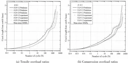
Fig.8 The comparison results of low-cycle fatigue crack growth life between the prediction andtest under different variable amplitude loadings
The predicted model Eq.(8)can be well used to evaluate the low-cycle fatigue crack propagation life under the tensile/compressive overload,based on the proposed model of the lowcycle fatigue crack growth rate in this study,which have a good accuracy.Confined to the space and the same prediction relationship,the predicted values of the low-cycle fatigue crack growth life with different cases,such as different mean stresses and stress ratios,and so on,are not displayed repeatly in this study.
4 Conclusions
The low-cycle fatigue crack propagation behavior of ship cracked plate is studied under variable amplitude loading considering the effect of accumulative plasticity in this study.The lowcycle fatigue crack growth behavior of ship cracked plate can well evaluated by the predicted model proposed in this study under the tensile/compressive overload with a single peak.
Additionally,the obvious retardation effect emerged at the crack tip of cracked plate with the Q235 steel after the tensile overload peak,and then the low-cycle fatigue crack propagation gradually recovered the level of the constant amplitude loading.The larger the tensile overload ratio is,the more remarkable the retardation effect is;however,the stress ratio has an opposite influence on the retardation effect.The acceleration effect will be produced under the compressive overload,but the affect range of the acceleration effect is much lower than the retardation effect.
[1]Deng J L.Research on low-cycle fatigue strength of ship hull plate based on accumulated plastic damage[D].Wuhan:Wuhan University of Technology,2016.(in Chinese)
[2]Ding Zhenyu.A study on intrinsic mechanism of crack propagation behavior subjected overload[D].Hangzhou:Zhejiang University of Technology,2013.(in Chinese)
[3]Tvergaard V.Effect of underloads or overloads in fatigue crack growth by crack-tip blunting[J].Engineering Fracture Mechanics,2006,73:869-79.
[4]Mansour A E,et al.An experimental investigation of ship hull ultimate strength[J].Trans.SNAME,1968,98:411-439.
[5]Murray J M.Structural development of tankers[J].European Shipbuilding,1953,3(5):69-75.
[6]Skorupa M.Load interaction effects during fatigue crack growth under variable amplitude loading-a literature review[J].Part II:Qualitative Interpretation.Fatigue Fract.Eng.Mater.Struct.,1999,22:905-26.
[7]Shijve J,Broek D.The result of a test program based on a gust spectrum with variable amplitude loading[J].Aircraft Engng,1962,34:314-316.
[8]Meggiolaro M A,de Castro J T P.On the dominant role of crack closure on fatigue crack growth modeling[J].International Journal of Fatigue,2003,25(9-11):843-854.
[9]Christensen R H.Fatigue crack,fatigue damage and their detection[M].Metal Fatigue.New York:MacGraw-Hill,1959.
[10]Jones R E.Fatigue crack growth retardation after single-cycle peak overload in Ti-6Al-4V titanium alloy[J].Engng.Fract.Mech.,1973,5:585-604.
[11]Silva F S.The importance of compressive stresses on fatigue crack propagation rate[J].International Journal of Fatigue,2005,27(10-12):1441-1452.
[12]Skorupa M.Load interaction effects during fatigue crack growth under variable amplitude loading-a literature review.Part I:Empirical trends[J].Fatigue Fract.Engng.Mater Struct.,1998,21:985-1006.
[13]Zheng X,Cui H,Su X.Numerical modeling of fatigue crack propagation based on the theory of critical distances[J].Engineering Fracture Mechanics,2013,114:151-165.
[14]Yao T,Nikolov P I.Buckling/plastic collapse of plates under cyclic loading[J].J Soc.Naval Arch Japan,1990(168):449-462.
[15]Kang G Z,Gao Q,Cai L X,et al.Experimental study on the uniaxial and nonproportionally multiaxial of SS304 stainless steel at room and high temperatures[J].Unclear Engineering and Design,2002,216:13-26.
[16]Creager M,Paris P C.Elastic field equations for blunt cracks with reference to stress corrosion cracking[J].Int.J Fract.Mech.,1967,3:247-52.
[17]Jiang Y Y,Feng M L,Ding F.A reexamination of plastivity-induced crack closure in fatigue crack propagation[J].International Journal of Plasticity,2005,21(9):1720-1740.

- 船舶力学的其它文章
- Study on Vibration Characteristic of Jacket Platform Considering the Structure-Pile-Fluid-Soil Interaction
- Study on Dynamic Response of Cargo Hold Structure of CNG Carriers under Gas Explosion Loading
- Efficient Simulation of the Slamming Loads Using the Hybrid Two-Step Solution
- Simulation of Brittle-Ice Contacting with Stiffened Plate with Peridynamics
- Investigations on the Mechanical Behavior of an Innovative Subsurface Tension Leg Platform in Ultra-Deep Water(Part I)
- LES Simulations of the Flow Around a Propeller in Crash Back and Crash Ahead