
Simulation of Brittle-Ice Contacting with Stiffened Plate with Peridynamics
2018-03-28 12:30:25WANGQingWANGYiYUANLihaoLUWeiZHANGYiheng
船舶力学 2018年3期
WANG Qing,WANG Yi,YUAN Li-hao,LU Wei,ZHANG Yi-heng
(College of Shipbuilding Engineering,Harbin Engineering University,Harbin 150001,China)
0 Introduction
Increasing demand of oil and gas exploration leads to great interest of cold-region techniques.In Arctic regions,ice actions play a main role in performance of naval architectures like lighthouses,channel markers,bridge piers,polar-region ships and drilling platforms.As a result,to guarantee the safety of human activities in cold regions,an accurate estimation of ice forces and in-depth understanding of ice behaviors is necessary.
During interaction between sea ice and naval structure,the ice failure may experience bending,buckling,crushing or combination of them.By crushing failure,the ice-structure interaction results in creep deformation and brittle failure.Loading with high speed brings about brittle flaking and fracture.By contrast,ductile failure appears during low-speed loading.Failure modes in full-scale measurement of Molikpaq structure are shown in Ref.[1].Jukka Tuhkuri[2]conducted a laboratory test of ice-structure interaction and provided a clear observation of brittle flaking during the experiment.Results of the test indicate that the value of ice force was affected by the clearance between structure and confinement of ice.Pressure on flat structure shows line-like area where the pressure is greatly higher than any others.The line-like contact was also observed in the indentation tests conducted by Sodhi[3].By pushing segmented indentors into the edge of freshwater ice sheet with various velocities,results of the tests implicate that there is simultaneous generation of forces on all segments during low-velocity indentation,whereas there is a non-simultaneous force acting on the segments during high-velocity indentation.With advanced numerical techniques,the numerical simulation and computational mechanics can play a crucial role in developing safer cold-region structures and understanding phenomenon in ice-structure interaction.
Great number of numerical approaches have been used to address different topics related to ice-structure interaction.Conventional computational methods are usually based on continuum mechanics like finite element method[4].Even though finite element method has been developed as one of the most widespread techniques all over the world,it is facing some problems to deal with fracture,crack propagation and damage in solid material.Because it attempts to solve the partial differential equations of the classical theory of continuum mechanics for analyzing deformation in structures.Yet these equations,because they require the partial derivatives of displacement to be known throughout the region modeled,are in some ways unsuitable for the modeling of discontinuities in which these derivatives fail to exist.
Extended Finite Element Method(XFEM)[5]introduces auxiliary equations,which solve the problem caused to differential operators by the presence of discontinuities,to predict nucleation and propagation of a crack.But,in particular to 3D analysis,such auxiliary equations are not always easy to apply.Interface elements(or cohesive zone models)[6-7]is another strategy to study the crack propagation problem.However,only when the path of the discontinuity is known a priori it can be applied and it is limited by the element discretization.
Other numerical methods,such as the atomistic model[8],describe dynamic fracture as a rupture of atomic links using a nonlocal approach,but because of limited computational efficiency,coupling them with other computational methods is necessary for more efficient at the macro-scale level,such as finit element analysis(FEA).However,when they make use of concurrent multiscale models[9]to couple,rather complex strategies for a correct transfer of the forces between models of different scale are needed.In addition,spurious forces[10],which affect equilibrium in the transition zone between the two different models,are often generated during coupling between the local and non-local models.
Silling[11]reformulated completely the basic equations of continuum mechanics when he realized the aforementioned limitation.The resulting approach is known as the peridynamic theory.This theory is a nonlocal theory that does not require spatial derivatives.It provides nonlinear material response with respect to displacements.The main difference between the peridynamic theory and classical continuum mechanics is that the former is formulated by using integral equations as opposed to derivatives of the displacement components.This feature allows damage initiation and propagation at multiple sites with arbitrary paths inside the material without resorting to special crack growth criteria.In the peridynamic theory,internal forces are expressed through nonlocal interactions between pairs of material points within a continuous body,and the damage is a part of the constitutive model.Interfaces between dissimilar materials have their own properties and the damage can propagate when and where it is energetically favorable for it to do so.
In this study,the bond-based peridynamic theory,a non-local method,is first briefly explained in Chap.2.Then the mechanical properties of sea ice are described and the constitutive model of sea ice in peridynamic theory is established in Chap.3.A description of the numerical implementation is presented in Chap.4.Simulation results to demonstrate the capability of peridynamic theory for ice-structure interaction by comparison with the previous experimental date are presented in Chap.5.
1 Theory of peridynamics
The peridynamic theory[11]applies integration of forces acting on a material point,which avoids the mathematical problems that partial differential method faces when addressing discontinuities.Furthermore,extra criterion is not required for determining crack growth and branching,compared to conventional elastic fracture mechanics,which allowing crack growth and branching proceed spontaneously.
The peridynamic theory introduces a ‘horizon’ in which the material point interacts with each other by ‘bonds’ and forces of material points are integrated over the horizon which is a positive number δ.As a result,a material point exerts force on not only the nearest points but also all points in the horizon(See Fig.1).That is why peridynamic model is known as a nonlocal method.
The basic theory of peridynamics is briefly introduced in this section.For a continuum,the governing equation of a material body can be written as:

where f is the ‘pairwise force function’ carrying out the relations(bond force)between subjective material point x and other material points in its horizon and u is displacement vector of material points.Integration is implemented in horizon space.ρ is material density and b is body force acting on point x.Hxis a neighborhood of material point x.Position vector ξ=x-x′as the relative position of two points in reference configuration and their relative displacement are defined.

According to Ref.[12],it can be assumed that the scalar bond force f depends only on bond stretch s(or bond strain)

The definition indicates that s is the critical bond stretch of bonds connecting each point.As long as a bond is stretched beyond critical bond stretch which is defined as s0described in following content,the bond breaks permanently.This is how peridynamic theory introduces damage into continuum mechanics.The critical bond stretch s0can be derived by considering the energy release rate when bonds break.To completely separate the body into two halves across a fracture surface as shown in Fig.2,all bonds that initially connect particles in the opposite halves need to break[12].

Fig.1 Each point x in the body interacts directly with points in the Hxthrough bonds

Fig.2 Evaluation of fracture energy
The energy in each unit fracture area needed to completely separate the body into two halves is the energy release rate G0,which is a measurable value for a material.Let w0(ξ)denote the work required to break a single bond.For the microelastic material,

The work G0required to break all the bonds per unit fracture area is then found from

after evaluation of these integrals,the energy per unit fracture area for complete separation of the two halves of the body is found.Because the energy release rate is a measurable quantity for materials,Eq.(4)allows s0to be evaluated under the assumptions of complete separation of the fracture surfaces and of the absence of other dissipative mechanisms near the crack tip.Solving Eq.(4)for s0leads to

where c is the micropotential constant described in following content and δ is the horizon size.
Since the material(ice)in this study is assumed to be isotropic,f is independent of the direction of ξ.Therefore,as elastic brittle material(ice)is considered,pairwise force function is simplified as:

where c,which indicates the bond elastic stiffness,is the micropotential constant in the peridynamics and μ is a judgment function to determine whether bond force exists.The micropotential constant c can be derived through the equivalent of elastic strain energy in peridynamics and elasticity theory.For homogeneous deformations under isotropic extension,the micropotential is thus expressed as

where w is the micropotential which is the energy in a single bond and has dimensions of energy per unit volume squared.s is the bond stretch described in Eq.(2).In the case of the onedimensional model,the energy per unit volume of the body at a given point can be derived as

where A is the cross-sectional area of a one-dimensional bar.The strain energy density for elastic material in classical theory with the same homogenous deformation is expressed as

where E is the elastic modulus and s denotes strain in classical theory being equal to the bond stretch in peridynamics described in Eq.(7).Setting the energy in Eq.(8)equals to the strain energy density of the classical theory and solving for c gives

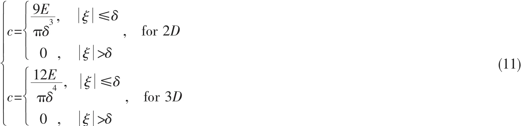
The derivations of c for two-dimensional and three-dimensional models are similar to onedimensional model and final expressions for c can be expressed as
The value of function μ takes either 1 or 0.μ=0 means that the bond is broken,otherwise the bond still links the given two points.

Consequently,the bond force of elastic brittle material is only characterized by two parameters:c and s0.From Eq.(5)and Eq.(10),both c and s0are related to the mechanical properties of material.
2 Sea ice
Many kinds of materials such as fresh water ice,brine,gas and different types of solid salts constitute the sea ice,which leads to mechanical dependence on the temperature.So the sea ice is a complicated material.The mechanism of sea ice growth could form several different grain structures due to environmentally dominated variations depending upon the predominant conditions.The most universal grain structures contain granular,columnar and discontinuous columnar[13].Since granular ice is isotropic in general,which means that direction of measurement on ice has little influence on properties of ice.In addition,granular ice could come into being conveniently in indoor lab.Therefore,granular ice is a commonly-used solid material in lab experiment and numerical simulation.
According to Ref.[14],during ice crushing,ice represents three modes regarding with strain-rate.Ductile failure and brittle failure stand for two typical kinds of sea ice failure behaviors,the transition from ductile to brittle is shown in Fig.3.Ice is a ductile material with plastic mechanical behavior when strain-rate is low.When strain-rate is higher than 10-1s-1,ice performs as ductile material shrinking by 10%or more without collapse.Ductile-brittle transition region is under medium strain-rate.When strain-rate is high,ice is an elastic brittle material.Ice behaves as brittle material and collapses after shortening around 0.1%when is fleetly loaded(10-7-10-1s-1)[15].

Fig.3 Ductile to brittle transition of ice[15]

Fig.4 Constitutive model of ice
During ice engineering,what attracts most attention of engineers is the brittle failure of sea ice.Some researchers do experiments to study brittle strength,failure patterns and characteristics of ice-structure interaction[16-19].Ice has different compressive strength and tensile strength,with the compressive strength being around 3-4 times the tensile strength[20].By contrast,ductile failure mostly happens when loading rate is very low.Thus,brittle failure has a great influence on research about ice-structure interaction.As described,brittle-ductile transition of sea ice has a great effect on failure strength and failure pattern.However,peridynamics is lack of concept of strain of classical mechanics.As a result,it is of great difficulty to use strain-rate as control of the transition.Even though bond strain and ductile force function can be achieved,deficiency of relevant experimental data makes setting accurate value difficult in numerical simulation.It is suitable and effective to use brittle material model in peridynamic simulation on failure of sea ice.In bond-based peridynamic theory,a linear elastic constitutive model of ice is established as shown in Fig.4.In Fig.4,the bond force represents stress and the bond stretch represents strain.st=s0is the critical bond stretch andthe critical bond compression.If the bond stretch exceeds stin the tensile case or scin the compressive case,the bond will break and there is no bond force.
3 Numerical method
Discretization:After the homogeneous domain is discretized by unit cell volumes occupied by material points.Governing equation can be transformed to discretized form:

where f is the pairwise force function.i is the number of points in a given body and p is the point interacting with point i.n is the number of time step.The unit volumethree-dimension model.
Time integration and numerical stability:To acquire acceleration of points,central differentiation method is applied to proceeding time integration:

which means acceleration of point i at time t is dependent on displacements of point i at t+Δt,t and t-Δt.The algorihm flow chart is shown in Fig.5.Athough time integration method is straightforward,integrating process is conditionally stable.There,Ref.[12]applied von Neumann stability analysis to limit the time step size Δt,which optimizes the stability of explicit time integration:

The horizon size can be chosen according to the characteristic length dimensions.For nanoscale analysis,the horizon would be determined by the distance over which physical interactions between atoms or molecules occur.However,for macroscale analysis,the horizon does not have a physical correspondence and its value can be chosen according to convenience[12].In practice for macroscale modeling,the value δ=3Δx usually works well.
Short-range repulsive force:In the case of interaction problem,a force density between material points belong to different bodies is defined by Ref.[12].This force density is based on a critical distance,rsh,between two material points of two different bodies when they come close to each other.Since specific two points are close enough,they begin to push each other in order to prevent sharing the same location.The force density for interaction is expressed as:

where the force constant,csh,can be chosen as:

And critical distance,rsh,can be chosen as:


Fig.5(a)The flow chart of simulation

Fig.5(b)The computation of bond force
4 Numerical simulation
This chapter presents the process of developing the numerical simulation,including operating conditions and numerical parameters,and the result of total ice force obtained from simulation.
4.1 Operation setup
This study presents a numerical example pushing ice sheet contacting with strengthened ship hull with peridynamic method.The ice sheet is a cube with 1 200 mm length,800 mm width and 200 mm thickness.Ice,in this study,is simplified as homogeneous brittle-elastic material with compressive strength of 2.6 MPa,density of 860 kg/m3and Poisson’s ratio of 0.3.These physical mechanics parameters of ice are the same with the model ice in the experiment[21].As for the fracture energy G0and elastic modulus,which are based on Ref.[22],Pieti Marjavaara et al,who are the authors of Ref.[21],used cohesive surface methodology to simulate successfully the ice crushing experiments[21].All applied material properties of ice in Ref.[22]are based on the mean values given by Määttänen et al[21].The elastic modulus is 7 GPa.The fracture energy is taken as a typical and reasonable value of 30 J/m2for ice.Because the fracture energy is hard to measure in practice,a method based on fracture toughness,which is relatively easy to get from experiments,is introduced to calculate the value of fracture energy[23].To introduce damage in ice using peridynamics,critical stretch for breakage of peridynamic bond is 5.455×10⁻⁴based on Eq.(5).By using a boundary at the edge of level ice,the ice sheet acquires a velocity towards to stiffened plate.The size of boundary region is approximately 3 times of grid spacing,see Fig.6.The total area of ship hull or offshore structure plate is 1 000 mm×220 mm.The structure plate with 12 mm thickness contains three T section stiffened panels.The three stiffened plates have 300 mm spacing.These structural dimension parameters are in agreement with Ref.[21].Except hull plate,the T section panels are assumed as rigid body free of deformation.We use the steel with density of 7 800 kg/m3and elastic modulus of 210 GPa as the material of stiffened plate.
For both level ice and stiffened plate,the two bodies are both discretized as material particles.Grid spacing of discretization is 4 mm with consideration of computational accuracy and cost,which means that the ice plate involves approximately 300 000 material particles.According to the time stabilization criterion in Eq.(15)for both bodies with different density,the time step size is set as 8.406 2×10⁻⁷s.

Fig.6 Configuration of simulation
4.2 Results and discussion
Ice is a special type of engineering material.Number of experiments indicated that ice is brittle material when strain rate is high and ductile failure happens during low-speed interaction.Mauri Määttänen conducted an experiment of ice sheet crushing with stiffened plate with 1:3 scaled model in 2011 to study the interaction[21].In this experiment,the ice velocity how to affect ice failure modes was analyzed.The ice failure modes and their dependence on ice velocity are as expected.At low ice velocity below 0.1 mm/s,the ice failure mode is continuous ductile creep and has constant pressure distribution.At velocities of 1 mm/s and above,the ice failure turns into brittle mode and produces a high initial load peak.This load history is typical to any constant ice velocity>0.9 mm/s.For the brittle failure mode,ice-induced force is resulted from the experiments seen Fig.7.In the brittle failure mode in Fig.7,there is only elastic deformation of ice in the stage of ice-induced force changed from zero to the initial peak.Ice failure will appear until the ice-induced force reaches the initial peak.After the initial peak continuous spalling type ice failure reduces significantly the total crushing load,and keeps persistent high local contact pressure-line like contact-only at the centre part through the ice thickness.In addition,regarding with the number of grid points and time steps,the balance of sufficient accuracy and numerical efficiency is of great importance for peridynamic method.Further,peridynamics is an emerging theory and the concept of creep and ductile deformation are still in development in the bond-based peridynamics.Although the creep and creep-fracture transition are good ideas,they are really difficult to apply in the bondbased peridynamics more realistic and reasonable.So only the elastic deformation phase of iceinduced force changed from zero to the initial peak was simulated in this paper.The stage after the initial peak was not simulated here.The ice velocities simulated in this paper were all above 1 mm/s and the ice-induced force simulated did not reach the initial peak,so there is no appearance of creep,creep-fracture transition or fracture deform characteristics.

Fig.7 Ice force of brittle failure in ice[21]
In order to learn more about the process of ice-structure interaction and examine the accuracy of simulation of ice-structure interaction with peridynamics,the ice force caused by ice crushing is outputted from numerical simulation,shown in Tab.1.Comparison of the ice force in numerical simulation and experiment given in Tab.1,reveals that the maximum error is 8.81%,the results of the numerical simulation are consistent with the experimental results.As for reasons for the error,the mechanical properties of ice are affected by the porosity and salinity.In contrast,in this paper,ice forces obtained by peridynamics are independent from these factors which will be taken into consideration in future work.Furthermore,how the size and arrangement of ice crystal affect the deformation of ice are undetermined.The numerical computation considering the size and arrangement of ice crystal will be analyzed in future research.

Tab.1 Comparison of the results
Fig.8 indicates visual reports of numerical simulation with stress contour plot.From the figure,it is clearly observed that high-stress area of structured plate appears firstly at the area contacting with ice sheet and spread to whole plate from directly contact area.After that,with increasing stress on crushed plate,four circle hot spot with higher stress appears on structure below and above ice sheet.The reason for this phenomenon described above is the free level of frame span.The span between two reinforced frames is relatively more free and,thus,susceptible to deformation.Because only the elastic deformation phase was simulated in this paper,so the line like contact,which is seen in the experiment due to the whole process from deformation to failure of ice performed,can not appear in Fig.8.Under the ice force,the maximum deflection of target plate is 0.011 mm which is in the same order as 0.013 mm in the experiment[21].
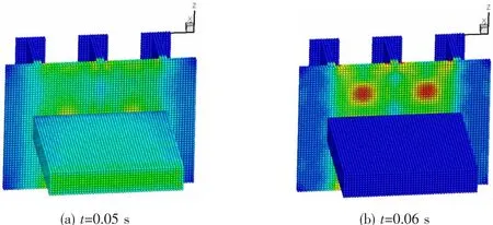
Fig.8 Virtual reports of numerical simulation

Fig.9 Ice pressure distribution at stiffened plate[24]

Fig.10 Ice force distribution during simulation
Design of ship hull structure in Arctic region always makes an assumption that the plate with reinforcements surfers higher ice pressure and lower ice pressure happens at free plate span[24],see Fig.9.The ice load distribution versus width of crushed plate of numerical simulation is shown in Fig.10.It clearly indicates that the ice force at the middle of plate,the free span between two stiffened frames,comes to the minimum.In addition,the closer to frames the point is,the higher the ice pressure.In other words,the numerical results of ice force versus plate width agree well with experimental assumption.
5 Conclusions
This paper presents a study of applying a non-local,meshfree method called‘peridynamics’,which is a nonlocal theory using integration rather than differentiation to calculate displacement and requiring no need for predefined crack propagation path,to simulate the progress of interaction between level-ice and ship hull plate with stiffened panels.In the simulation,the frames are assumed to be rigid but the plates between the frames under ice loading are flexible.Ice is simplified as elastic-brittle ice which is of great interest to engineers.Basic theory of bond-based peridynamics is briefly introduced and the numerical method,such as discretization and time-integration stability,is discussed.To implement two-body interaction in peridynamic model,an interaction force density is applied to prevent material particles belonging to different bodies from sharing the same position.To determine the feasibility and accuracy of applying peridynamic method on ice-structure interaction,numerical results that agree with data from experiments reveal that peridynamic theory and algorithms can be used to simulate ice-structure interaction.The visual images including deformation of stiffened plate,deformation of level ice and progress of interaction are shown in this study.With visual results,it can be clearly observed that,during moving ice crushing structure,deformation of structured plate can be clearly observed.After that,simulation records of ice load distribution versus width of crushed plate show higher pressure when material points are close to stiffened frames and lower pressure at free span of plate,which agrees well with experimental assumption.It concludes that peridynamics is a preeminent numerical method to simulate ice-structure interaction.
Acknowledgement
The support of the Marine Engineering Equipment Scientific Research Project of Ministry of Industry and Information Technology of PRC,the College of Shipbuilding Engineering,Harbin Engineering University(Grant No.GK1010900090),the National Science and Technology Major Project of China(Grant No.2016ZX05057020)and the National Natural Science Foundation of China(No.51639004)are gratefully acknowledged.
[1]Timco G W,Johnston M.Ice loads on the molikpaq in the canadian beaufort sea[J].Cold Reg.Sci.Technol,2003,37(1):51-68.
[2]Tuhkuri J.Experimental observations of the brittle failure process of ice and ice-structure contact[J].Cold Reg.Sci.Technol,1995,23(3):265-278.
[3]Sodhi D S.Nonsimultaneous crushing during edge indentation of freshwater ice sheets[J].Cold Reg.Sci.Technol,1998,27(3):179-195.
[4]Bergan P G,Cammaert G,Skeie G,et al.On the potential of computational methods and numerical simulation in ice mechanics[C]//IOP Conference Series:Materials Science and Engineering.IOP Publishing,2010,10(1):012102.
[5]Belytschko T,Chen H,Xu J,Zi G.Dynamic crack propagation based on loss of hyperbolicity and a new discontinuos enrichment[J].Int.J Numer.Methods.Eng,2003,19(58):1873-1905.
[6]Mi Y,Crisfield M A,Davies G A O,Hellweg H B.Progressive delamination using interface elements[J].J Compos.Mater,1998,32(14):1246-1272.
[7]Munoz J J,Galvanetto U,Robinson P.On the numerical simulation of fatigue driven delamination with interface elements[J].Int.J Fatigue,2006,28(10):1136-1146.
[8]Zhou S,Lomdahl P,Thomson R,Holian B.Dynamic crack processes via molecular dynamics[J].Phys.Rev.Lett,1996,76(13):2318-2321.
[9]Lee J,Wang X,Chen Y.Multiscale material modeling and its application to a dynamic crack[J].Theor.Appl.Fract.Mech,2009,48(51):33-40.
[10]Shenoy VB,Miller R,Tadmor E B,Rodney D,Phillips R,Ortiz M.An adaptive finite element approach to atomicscale mechanics:The quasicontinuum method[J].J Mech.Phys.Solids,1999,23(46):611-642.
[11]Silling S A.Reformulation of elasticity theory for discontinuities and long-range forces[J].J Mech.Phys.Solids,2000,48(1):175-209.
[12]Silling S A,Askari E.A meshfree method based on the peridynamic model of solid mechanics[J].Comput.Struct,2005,83(17):1526-1535.
[13]Timco G W,Weeks W F.A review of the engineering properties of sea ice[J].Cold Reg.Sci.Technol,2010,60(2):107-129.
[14]Yue Q,Guo F.Dynamic ice forces of slender vertical structures due to ice crushing[J].Cold Reg.Sci.Technol,2009,56(2-3):77-83.
[15]Schulson E M.The brittle failure of ice under compression[J].J Phys.Chem.B,1997,101(32):6254-6258.
[16]Jones S J.The confined compressive strength of polycrystalline ice[J].J Glaciol,1982,28:171-177.
[17]Kamio Z,Matsushita H,Strnadel B.Statistical analysis of ice fracture characteristics[J].Eng.Fract.Mech,2003,70(15):2075-2088.
[18]Bergan P G,Cammaert G,Skeie G,et al.On the potential of computational methods and numerical simulation in ice mechanics[C]//IOP Conference Series:Materials Science and Engineering.IOP Publishing,2010,10(1):012102.
[19]Jordaan I J.Mechanics of ice-structure interaction[J].Eng.Fract.Mech,2001,68(17):1923-1960.
[20]Karr D,Das S.Ice strength in brittle and ductile failure modes[J].J Struct.Eng.1983,109(3):2802-2811.
[21]Määttänen M,Marjavaara P,Saarinen S,et al.Ice crushing tests with variable structural flexibility[J].Cold Reg.Sci.Technol,2011,67(3):120-128.
[22]Kuutti J,Kolari K,Marjavaara P.Simulation of ice crushing experiments with cohesive surface methodology[J].Cold Reg.Sci.Technol,2013,92(92):17-28.
[23]Wang Q,Wang Y,Zan Y,et al.Peridynamics simulation of the fragmentation of ice cover by blast loads of an underwater explosion[J].Journal of Marine Science&Technology,2017:1-15,doi:10.1007/s00773-017-0454-x(Published online)
[24]Riska K,et al.Full scale observations of ship-ice contact[R].Helsinki University of Technology,Laboratory of Naval Architecture and Marine Engineering.Rpt.M-97,1990.

- 船舶力学的其它文章
- Study on Vibration Characteristic of Jacket Platform Considering the Structure-Pile-Fluid-Soil Interaction
- Study on Dynamic Response of Cargo Hold Structure of CNG Carriers under Gas Explosion Loading
- Efficient Simulation of the Slamming Loads Using the Hybrid Two-Step Solution
- Low-Cycle Fatigue Crack-Propagation Behavior of Ship Cracked Plate Considering the Accumulative Plasticity under Variable Amplitude Loading
- Investigations on the Mechanical Behavior of an Innovative Subsurface Tension Leg Platform in Ultra-Deep Water(Part I)
- LES Simulations of the Flow Around a Propeller in Crash Back and Crash Ahead