Efficient Simulation of the Slamming Loads Using the Hybrid Two-Step Solution
(1.State Key Laboratory of Hydraulic Engineering Simulation and Safety,Tianjin University,Tianjin 300072,China;2.Department of Naval Architecture and Ocean Engineering,Tianjin University,Tianjin 300350,China;3.China Ship Scientific Research Center,Wuxi 214082,China)
0 Introduction
When the ship sails in rough seas,the bow structures will encounter the hydrodynamic slamming due to the large relative motion between structures and waves.The impulsive slamming loads acted on the bow will threaten the safety of the local structures.It will also cause the ship whipping,which will affect the ship hull structures globally.Design against slamming load is the concern of ship designers from the view point of strength[1].
Prediction of local slamming loads usually involves two steps with different time scales.Firstly,relative motions between the ship and waves are predicted by the time domain simulations using the linear or nonlinear ship motions theories,such as Guedes Soares,1989[2]and Luo et al,2007[3].Once the impact velocity is obtained,the local slamming loads are determined by different variations of formulations based on Wagner theory,1932[4],such as Ochi and Motter,1973[5],Hu et al,2005[6],Hermundstad and Moan,2005[7].For the local slamming problem,due to the complexity of the 3D flow around the 3D bow structures,it is always simplified as 2D section problem in the simulations.More efforts are encouraged to be devoted on the second step in order to capture both the peak and also the time history of the slamming pressures.
As part of the MARSTRUCT network of excellence,Brizzolara et al,2008[8]carried out investigations to compare pressures and resultant forces predicted by BEM,SPH and commercial software packages LS-DYNA,FLOW-3D and FLUENT,with experimental measurements obtained from drop tests for a bow section(Aarsnes,1996)[9].Luo et al,2011[10]carried out simulation on water entry of 2D wedge using the LS-DYNA code.Yue,2016[11]predicted the impact pressures of one wedge and the bow section with heel angles using CFD code FLUENT and compared with experimental results.It shows that the CFD type approach has the potential to predict the slamming pressure accurately in time domain.
One hybrid two-step method is proposed in this paper to investigate the local slamming loads.The CFD method using the Finite Volume method(FVM)and dynamic mesh technology is applied as the second step.3D segment model is possible to be built for the local structures instead of the transverse section.Water entry of this model is simulated using the obtained relative motion and then the slamming pressures are obtained in time domain.This method is applied to predict the bow slamming of one VLCC in ballast condition.Numerical results are compared with those from model tests in irregular waves.Fair well agreements are achieved.
1 Hybrid two-step method
1.1 Investigation of relative motion using the potential flow theory
The global velocity potential for the ship advancingdecomposed into two parts,the potential of steady flowand that of unsteady flowin the linear theory[12].It is defined as,

where φSis the wave-making velocity potential associated with the ship advancing in calm water,and φTis the unsteady velocity potential which may be decomposed into independent components φIfor the incident waves, φDfor the diffracted waves,and φRfor the radiated waves.a is the wave amplitude,and j is the number of ship motion degrees.
The linear problem satisfies the following conditions,the Laplace equation,the linear free surface boundary conditions,the linear body radiation and diffraction boundary conditions and bottom boundary conditions.Three dimensional panel method using the Rankine source is usually applied to solve the problem for φ,such as the WASIM code.
The six-degree ship motions can be predicted once the velocity potential is obtained.Then the relative motion between the ship and the wave for the ship section with coordinate x along longitudinal direction is defined as

where zGis the heave motion, θyis the pitch motion(positive if clockwise),andis the wave height on ship section x.


where t0is the time instant when the body impacts the water.is the impact velocity.
1.2 Investigation of slamming loads using the CFD method
As the second step,the slamming process is simplified as the water entry of the local structures using the relative motions between the ship and the obtained wave.The CFD method is applied to simulate the water entry problem in the scaled-size model,but not the real size ship model.The 3D segment model instead of 2D transverse section of the ship is possible to be used.Symmetrical water entry or asymmetrical water entry with one heel angle can be simulated.In this paper,the symmetrical problem is discussed.The bow structures are built as one segment of the transverse section.
The FLUENT code is used for the slamming problem.The incompressible flow is governed by Navier-Stokes equations,i.e.,the mass and momentum conservation equations.The Volume of Fluid(VOF)multiphase flow model is applied to capture the air and water interface.Then the complex and nonlinear free surface phenomena during the water entry,such as the water-jet,can be simulated.
The Dynamic Mesh method is used to simulate the movement of the grids around the body during the water entry process.The hexahedron grids used in the computing domain are renewed for each iterative step using the Smoothing and Layering method.The movement of the boundary is specified by Profile file or UDF(User Defined Functions).The UDF defines the initial conditions,such as initial velocity of the model,the density of water,and the output data,such as the pressure,accelerated velocity,and the velocity at the specified location.
The Finite Volume method is used to disperse the governing equations into a series of algebraic equations.The discretization of the density and moment is carried out using the second order upwind scheme,while that of the turbulent kinetic energy and turbulent dissipation rate is carried out using the first order upwind scheme.The PISO(Pressure Implicit Split Operator)algorithm is applied to solve the algebraic equations,and then the velocity and pressure distributions in the flow field are obtained.So the simulation efficiency is improved and much accurate results will be obtained.
2 VLCC ship model
The proposed hybrid two-step method is applied to predict the bow slamming loads of one VLCC in ballast condition.The main particulars of the VLCC[13]are shown in Tab.1.Fig.1 shows the curve of the cross section where the number of station is 19.5.Point B is the position where the slamming loads is to be predicted and point O is at the bottom of the section.The coordinate values are listed in Tab.2.Figs.2 and 3 show the ship model used in WASM code.

Fig.1 The slamming position on cross section S2

Fig.2 The ship hull surface of the VLCC

Fig.3 The model meshes of the ship and water around

Tab.1 The main particulars of one VLCC

Tab.2 Slamming position
3 Prediction of the relative motions
Wave loads model tests of this VLCC was carried out in the tank of China Ship Scientific Research Center.The model scale is 1:77.Slamming pressures are measured at the position point B.Results in one irregular wave at the ballast condition are selected in this paper to compare with those from numerical simulations.ITTC spectrum is used,

The ship velocity is 17kns in the heading waves.The significant wave height is 15.0 m,and the period is 12.0 s.
The WASIM code is applied to predict the ship motions.The relative motions between the cross section S2 and the wave are obtained as shown in Fig.4.Dr_O means the relative displacement between point O and the wave.Vr means the relative velocity between the cross section S2 with the wave.As the ship hull is set as rigid,so the velocity on this cross section is the same as Vr.When Dr≤0,the slamming will occur on point O.Assuming the water uprise is ignored,then the slamming will occur on Point B
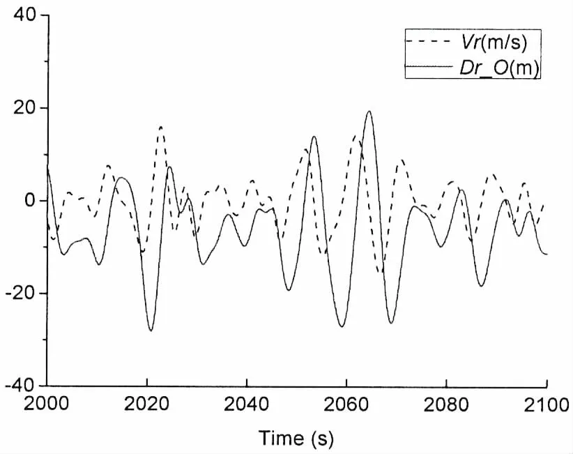
Fig.4 Relative motions of cross section S2
The statistical analysis is carried out for the motion responses in 3 600 seconds time.Slamming occurs 349 times on point O.Tabs.3 and 4 list the most severe three slamming events on points O and B.The slamming pressure will be predicted in the second step using the scaled-size model,not the real size ship.So results for the model are also listed.The scale is set as that in the model test. ‘t’ is the time instant when the slamming occurs on points O or B.‘v’ is the impact velocity.The subscript‘s’,‘m’ mean the data for the ship and the model,respectively.Figs.5,7 and 8 show the time histories of relative motions for slamming events 1,2 and 3 respectively in the model scale.

Tab.3 Relative motions on point O

Continue Tab.3

Tab.4 Relative motions on point B
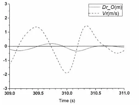
Fig.5 Relative motions for slamming event 1
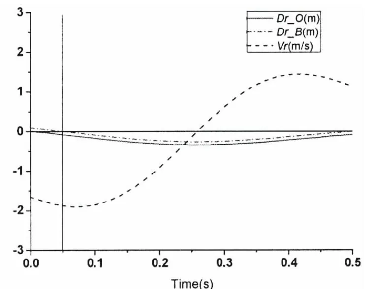
Fig.6 Zoomed relative motions for slamming event 1
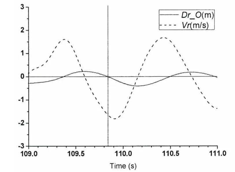
Fig.7 Relative motions for slamming event 2
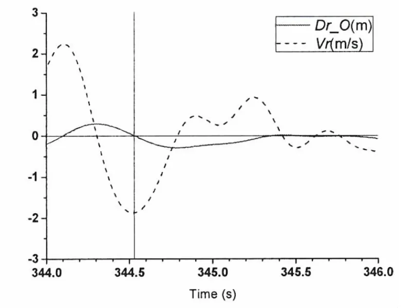
Fig.8 Relative motions for slamming event 3
It is shown in Fig.5 that the slamming occurs on point O when t=309.94 s.It is observed that Dr_O=0 and Vr=-1.717 m/s.If the time is set to 0 when the slamming occurs,then the next 0.5 s time history of the motions are shown in Fig.6.Dr_B means relative displacement between point B and the wave when the water uprise of the slamming is ignored.It is shown that the wave reaches the point B at time around 0.05 s.The predicted relative velocity of section S2 in this 0.5 s time period is fitted into one function as follows:

The similar fitted velocity formula can be obtained for slamming events 2 and 3.
4 Prediction of the slamming pressures
The CFD code FLUENT is used to predict the slamming loads on section S2 of the VLCC.The Finite Volume Method is applied using the PISO algorithm,Volume of Fluid(VOF)multiphase flow model and dynamic mesh method.The water entry of one segment formed by this transverse section S2 is carried out using the relative motions obtained above.The 3D flow on the 3D bow structures is ignored in the longitudinal direction.
The segment model is set up using the scale in the model test.Fig.9 shows the model setup in FLULENT.The width,height of the section is 0.52 m,0.39 m.The length of the segment is set as 1.00 m,which is around 2 times of the width in order to reduce the 3D slamming effect in the longitudinal direction.The width,height and length of the water domain is 3.00 m,1.4 m and 1.60 m.The height of the air domain is 0.60 m.
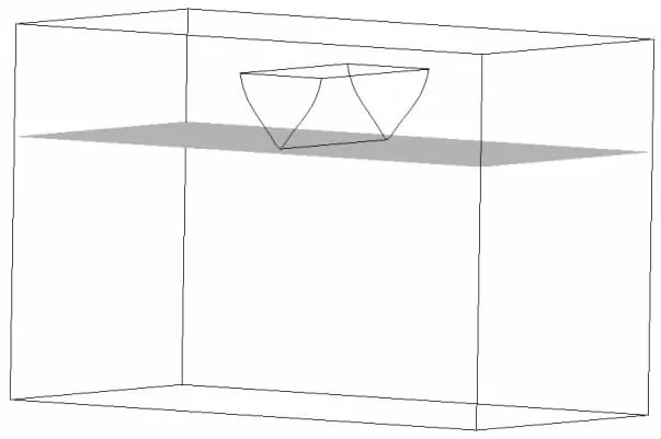
Fig.9 The global model setup in FLUENT
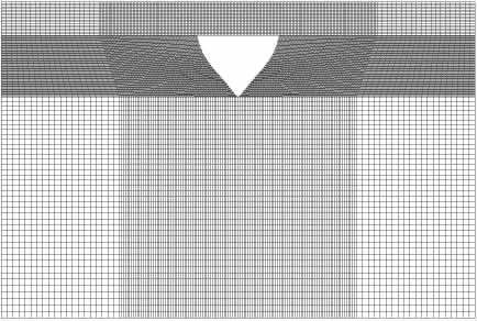
Fig.10 Local meshes around the segment
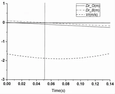
Fig.11 Relative motions(zoom)for slamming event 1
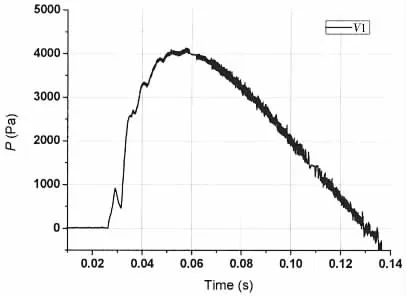
Fig.12 The time history of the pressure B for slamming event 1
The total fluids(air and water)domains are not uniformly meshed for the consideration of computational efficiency.Only the domain near the segment and also that segment will pass through are meshed with finer meshes.The finest mesh size is 0.006 m.Fig.10 shows the meshes near the segment.Total number of the meshes is 2.15 million.
The symmetric water entry is simulated using the relative motion obtained above.Only vertical velocity is considered.At first,the apex of the segment is located on the interface of the air and water domain.The initial velocity is-1.717 m/s for slamming event 1.The UDF is used to define the impact velocity described in formula(7).Then the segment will impact the calm water using this velocity time history.
Fig.12 shows the time history of the slamming pressure on point B predicted for slamming event 1.The time instant 0 here is 309.94 s in Fig.5 correspondently.The pressure starts to increase on about 0.02 s,and then increases quickly to the peak on about 0.05 s,and finally decreases to zero slowly.
In Fig.11,it is found that the slamming on points B occurs on about 0.05 s from relative motions predicted by WASIM,which is different from the results of FLENT.The reason is that the water uprise during the slamming can be obtained in CFD simulation,while that is not considered in the potential flow seakeeping code WASIM.The maximum pressure on point B is PB1=3 468.6 Pa.
Fig.13 shows the pressure contour on the segment surface and water uprise at different time instant during the water entry process.
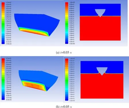
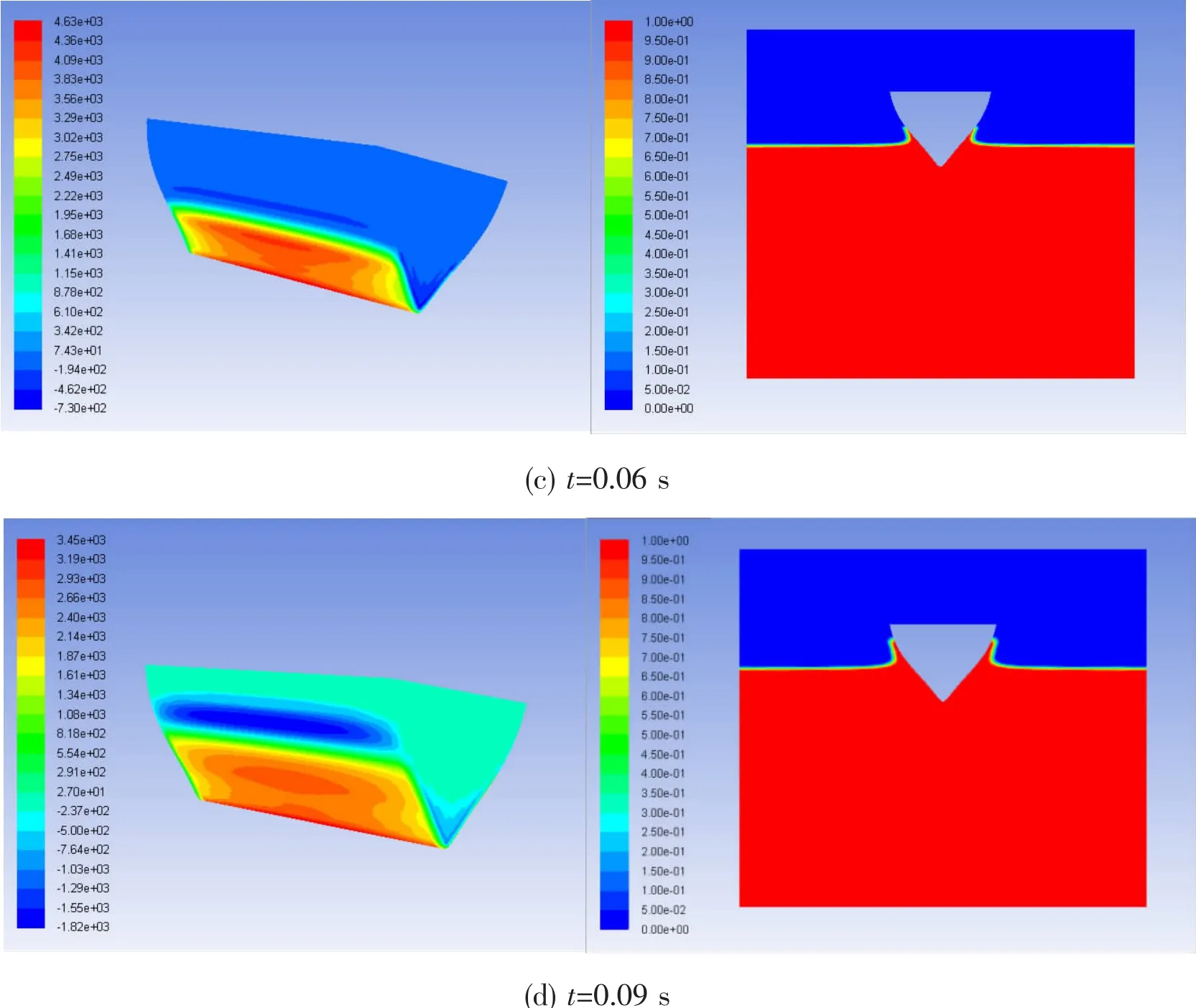
Fig.13 The pressure contour and water uprise during the water entry process
(1)The movement of the pressure contour on the segment surface is clearly observed.At the first instant,the maximum pressure is located near the apex of the segment.Then the pressures move up along profile of the transverse section with the movement of the water uprise.3D effect of the slamming pressures on the longitudinal direction is found.Assuming the segment length is L,it is divided into three parts, ‘1/4L’+‘1/2L’+‘1/4L’.The pressures in the middle part‘1/2L’is larger,and they do not change much along the longitudinal direction.But pressures decrease quickly in parts ‘1/4L’ moving toward the section ends.The pressure results in the middle part of the segment are chosen as shown in Fig.12.
(2)The movement of the water uprise along the section profile is clearly observed.When t=0.03 s,the uprise reaches point B closely.So the slamming pressure on point B shown in Fig.12 starts to increase sharply.When t=0.05 s,the water entry depth is almost equal to the draught of point B.The pressure on point B reaches the peak.And then the slamming pressure on point B decreases slowly when the uprise continues to move up.
Simulations are carried out for the slamming events 2 and 3,too.Figs.13 and 14 show the slamming pressures predicted for events 2 and 3.Peak values of the pressure are,PB2=3 165.4 Pa,PB3=2 698.2 Pa.The mean peak value of three slammings is Paver=3 110.7 Pa.Then the slamming pressure on the real ship is PB=3.11 kPa×77=239.5 kPa.
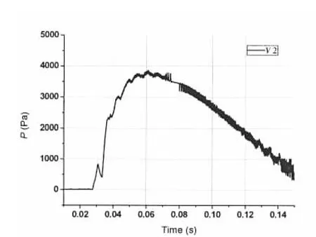
Fig.14 The time history of pressure B for slamming event 2
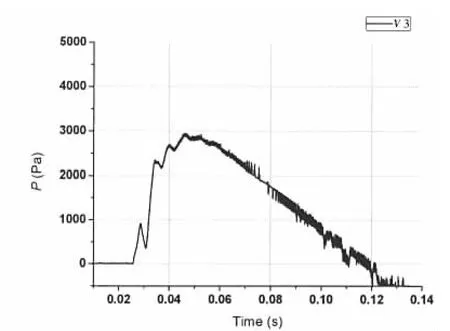
Fig.15 The time history of pressure B for slamming event 3
5 Comparison of the slamming pressure results
Tab.5 shows the comparison with pressure results in the irregular waves.The numerical simulation time on motions is 3 600 s as described in part 3 which is 410.26 s for the scaled-size model,which is almost equal to the tests time 397.07 s.The maximum statistical value is set as the 1/100 value,which is the maximum one among 100 samples.The average value of the three maximum slamming pressures among 349 samples in part 5 is regarded as the maximum one.The significant value is not simulated and is absent.

Tab.5 Comparison on statistical results of slamming pressures on point B
Formula using Wagner theory,1932 is also applied to predict the slamming pressure as follows:

It shows that the maximum value from CFD is 11%larger than that from tests.Fair well agreement is achieved between results of CFD and tests,the pressure value from Wagner formula is much larger than others.
6 Conclusions
One hybrid two-step solution is proposed to predict the local slamming loads on ship structures,which is the compromise of the numerical efficiency and the accuracy between the potential flow theory and the CFD method.The relative motions between the ship and the wave surface are predicted using the potential flow theory for the advancing ship in waves.Water entry of 3D segment model using the obtained relative motion is carried out.The local slamming pressures are predicted using CFD method based on FVM and dynamic mesh technology.The ship is of the real size scale in the first step while the structure is of the model size scale in the second step.The up-rise of the water jet and the local slamming pressures of the model during the water entry are captured.So the slamming loads of the ship in time domain can be predicted.
This solution has the potential to simulate the slamming pressure for the ships advancing both in heading and oblique waves.It is used to predict the bow slamming loads of one Very Large Crude Carrier(VLCC)in ballast condition.Relative motions on one bow section are studied and the slamming events are determined using the SESAM code.Slamming pressures of the most severe events in the 3D segment model are simulated using the FLUENT code.Water upsise and pressure contours are discussed.The predicted pressure results are compared with those from model tests in irregular waves.Fair well agreements are achieved.
[1]Luo Hanbing,Xu Hui,Yu Jianxin,Wan Zhengquan.Review of the state art of dynamic responses induced by slamming loads on ship structures[J].Journal of Ship Research,2010,14(4):439-450.(in Chinese)
[2]Guedes Soares C.Transient response of ship hulls to wave impact[J].Int.Shipbuilding Progr.,1989,36:137-156.
[3]Luo Hanbing,Qiu Qiang,Wan Zhenquan.Experimental study of whipping responses induced by stern slamming loads[C]//In:Proceedings of the 10th International Symposium on Practical Design of Ships and Other Floating Structures(PRADS).Houston,USA.2007,1:535-542.
[4]Wagner H.Uber stoss-und gleitvergange an der oberflache von flussig-keiten[J].Z.Angew.Math.Mech.,1932,12:193-215.
[5]Ochi M K,Motter L E.Prediction of slamming characteristics and hull responses for ship design[J].Trans.Soc.Naval Archit.Mar.Eng.,1973,81:144-176.
[6]Hu Jiajun,Cai Xingang.A forecast method of slamming pressure acting on the ship outside plates[J].Journal of Ship Research,2005,01:63-70.(in Chinese)
[7]Ole Andreas Hermundstad,Torgeir Moan.Numerical and experimental analysis of bow flare slamming on[J].Journal of Marine Science and Technology,2005,10:105-122.
[8]S.Brizzolara N Couty,Hermundstad O,Ioan A,Kukkanen T,Viviani M,Temarel P.Comparison of experimental and numerical loads on an impacting bow section[J].Ships and Offshore Structures,2008,3(4):305-324.
[9]Aarsnes J V.Drop test with ship sections-effect of roll angle[R].Marintek Report No.603834.00.01,1996.
[10]Luo Hanbing;Wang Shan,Guedes Soares C.Numerical prediction of slamming loads on a rigid wedge subjected to water entry using an explicit finite element method[C]//MARSTRUCT 2011.Hamburg,Germany,2011:41-48.
[11]Yue zhang.Numerical simulation of slamming induced loads on three dimensional structures with various angles[D].Tianjin:Tianjin University,2016.(in Chinese)
[12]Faltinsen O M.Sea loads on ships and offshore structures[M].Cambridge,UK:Cambridge University Press,1990.
[13]Gen Yanchao,Hu Jiajun.Wave loads model tests for one VLCC[R].Wuxi:China Ship Scientific Research Center,2015.(in Chinese)
- 船舶力学的其它文章
- Study on Vibration Characteristic of Jacket Platform Considering the Structure-Pile-Fluid-Soil Interaction
- Study on Dynamic Response of Cargo Hold Structure of CNG Carriers under Gas Explosion Loading
- Simulation of Brittle-Ice Contacting with Stiffened Plate with Peridynamics
- Low-Cycle Fatigue Crack-Propagation Behavior of Ship Cracked Plate Considering the Accumulative Plasticity under Variable Amplitude Loading
- Investigations on the Mechanical Behavior of an Innovative Subsurface Tension Leg Platform in Ultra-Deep Water(Part I)
- LES Simulations of the Flow Around a Propeller in Crash Back and Crash Ahead

