
Hydroelasitic Analysis of the Gravity Cage Subjected to Irregular Waves and Current
2018-03-28 12:30HUKeFUShixiao
船舶力学 2018年3期
HU Ke,FU Shi-xiao
(1.State Key Laboratory of Ocean Engineering,Shanghai Jiao Tong University,Shanghai 200240,China;2.Collaborative Innovation Center for Advanced Ship and Deep-Sea Exploration,Shanghai 200240,China)
0 Introduction
The offshore environmental problem is becoming a crucial issue for human society and the development of the nearshore aquaculture industry.Moreover,the demand for more sea foods high in protein is pushing engineers to design cost-effective fish cages that can withstand extreme environmental loads in deeper ocean conditions.Therefore,accurate prediction of a cage’s hydroelastic response has become a key focus in aquaculture engineering.
Previous investigations into sea loads on gravity net cages normally considered the impact of waves and currents separately.
First of all,the investigations into the wave loads exerted on the net cages focused on three main aspects:the loads on the net,the loads on the collar and the dynamic response of the fish cage system.
Concerning wave loads on the net,Lader[1]compared the changes in the wave height and energy before and after the wave passed through the net.Song[2]successfully predicted wave loads of the net by calculating the cubic net cage’s hydrodynamic response based on sinusoidal wave theory and the Morison equation,and he claimed that the relative error between the numerical prediction and test result was under 15%.Ito[3-4]simplified the wave condition intoforms of oscillating flow,under which the hydrodynamic forces on the net with different solidity ratios and pretensioning forces were studied.
In order to conduct detailed research into the wave loads on the collar,Krassimi[5]calculated the damping coefficient and added mass coefficient for the forced oscillating collar based on the potential flow theory.Kristiansen[6]later conducted a model test in a wave tank with a cylinder fixed on the free surface.He further investigated the nonlinearities in the wave forces on the collar caused by the influence of the free surface.
To quantify the response of the fish cage,Colbourne[7]conducted an experiment on multiple cages to compare the mooring forces under different kinds of wave loads.Fredriksson[8]and Fredriksson,et al[9-10]carried out a serious of experiments to investigate the mooring line forces and motion of the realistic fish cage.Besides,numerical simulations were also performed,and comparisons between experimental and simulated results indicated good agreements.By using the lumped mass point method and rigid body kinematics theory,Dong[11]and Xu[12]predicted the response of a net cage under irregular wave loads.
Secondly,in the case with current only(no waves),Aarnses[13]studied the drag force on the net cage,the changes in the cage’s volume and the reduction in current speed by towing a gravity cage model in calm water.Lader[14]conducted an experiment with a full-scale cage to specifically study the relationship between the current speed and cage’s volume.Huang[15]and Zhao[16-17]studied the hydrodynamic response based on the ‘lumped mass point method’.Huang found that the total force of the numerical model was lower than the experimental data when the Reynolds number was lower than the range of 1 400-1 800,while Zhao noticed that the volume of a net cage with diamond grids was larger than that with square grids.Berstad[18]calculated the mooring forces and the volume changes of a net cage by using finite element software(AquaSim).Moe[19]used ABAQUS to analyze the deformation of the net cage in currents with different speeds.Kristiansen[20]estimated the drag force and the volume changes of a net cage by replacing the twine’s drag and lift forces with each plane’s tangential forces and normal forces.The numerical results were in good agreement with the experimental data.
Based on the previous study,the hydrodynamics of the fish cage under wave or current loads has been researched extensively.Because irregular waves and currents normally co-exist in the real ocean environment,the dynamic response of the gravity net cage under the combined effects of irregular waves and currents needs to be further studied.Besides,because geometric nonlinearity due to net cage’s large deformation under the wave-current loads is evident,research on the full scale model should be conducted.
In this paper,a full-scale numerical model of a gravity net cage under irregular waves and currents was studied by using FEM.The irregular waves were simulated based on the JONSWAP wave spectrum.On this basis,the dynamic response of the floating collar,the modal contribution from each mode shape to the collar in the combined wave-current flows together and the changes in the mooring-line tension were analyzed.
1 Basic theory
1.1 Equations of motion
When the whole gravity cage is exposed to irregular waves and current,the dynamic equilibrium equations of the structure can be expressed as:

Both the wave forces fwand the current forces fccan be estimated by the modified Morison equation[21],where the velocity of the current and wave is superposed linearly,as shown in Eq.(3),

where CMrepresents the inertia coefficient,CM=Cm+1,Cdis the drag coefficient,D is the effective diameter of the beam elements and the truss elements,u and u˙represent velocity and acceleration of water particles in the wave-only condition.U is the current velocity and ρ is the water density.In the dynamic analysis where the motion of the structure must be taken into account,vpand aprepresent the velocity and acceleration of an element forming the structure.In this case,the influence of the mutual interference of the velocity field in the combined wavecurrent condition is not considered,see Lee[22].Based on the equation,the dynamic reponse of the net cage will be studied under wave-current combined condition,and the results will be further compared against those in wave-only condition.
1.2 Description of irregular waves
Several linear waves with random phase angles can be combined to generate an irregular wave.
Firstly,the elevation of water surface in an irregular wave can be written as:
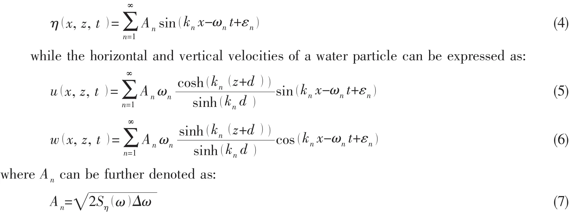
In the four equations above,An,kn, εnand ωnrepresent the wave amplitude,the wave number,the random phase angle and the circular frequency of the nth regular wave component,repectively.z is the vertical position of a water particle,d is the depth of the water,Sη( )ω is the wave spectrum and Δω denotes the difference between the circular frequencies of the measured components.The irregular wave was formed by choosing appropriate input parameters based on the JONSWAP wave spectrum,moreover,the significant wave height defined as the mean of the one third highest waves (H1/3)and the mean wave period (T1)in this paper were chosen as 3 m and 5 s,respectively.The corresponding wave spectrum is shown in Fig.1.
Based on the wave spectrum presented above,the time series at point(0,0,0)is shown in Fig.2.

Fig.1 JONSWAP wave spectrum with different significant wave height
1.3 Geometric nonlinearity
According to the small deformation hypothesis,the strain in a certain direction at an arbitrary point can be derived by calculating the first-order partial derivative of the corresponding displacement.Under this hypothesis,the large deflection and rotation of the element can be ignored when formulating the equilibrium.Nevertheless,due to the large deformation experienced by the structure,the geometric nonlinearities in the finite element analysis should be focused on in this study.

Fig.2 Wave elevation time series at point(0,0,0)
1.3.1 Strain-displacement relationship
When geometric nonlinearities are considered,the relationship between the stress and the strain can be expressed as:


1.3.2 Stress-displacement relationship
The relationship between the increment of stress and that of strain can be expressed as:

where[D]is the constitutive matrix for the material.Combining Eqs.(8)-(10)can lead to Eq.(11),

1.3.3 Equilibrium equation
Based on the principle of virtual work,the equilibrium equation can be expressed as:

Eq.(15)is the basis for solving geometric nonlinear problems.In this equation,is a standard linear stiffness matrix,is the initial-stress matrix for nonlinear conditions,andis the initial displacement matrix under large deformation.The three matrices can be expressed as:


1.4 Modal superposition method
In order to have an overview of the motion and deformation of the system,it is important to study the global deformation of the floating collar at first.Even though it is impossible to use modal superposition method to predict the nonlinear hydrodynamic response of the floating collar,the method can still be considered as a ‘data post-processing’ procedure.Based on the predicted nonlinear hydroelastic results,the method can be applied to analyze the weight of the participation of each mode at any instant.
In this method,the hydrodynamic response of the floating collar can be described as a linear superposition of all the possible motion and deformation modes:


After multiplying both sides of Eq.(21)bythe modal-weight matrix at time t can be rewritten as:

Therefore,the standard deviation of the modal weight can be derived as follows:

where T is the total time length and)symbolizes the time-averaged modal weight.
2 Finite element model descriptions
Numerical and experimental results in the previous work by Lader[14]and Berstad[18]have shown that the bottom nets normally have a negligible effect on the global dynamic response of fish cages.Therefore,in the finite element model,the bottom net and its knots were excluded.The numerical model of the whole gravity net cage is shown in Fig.3.The numerical model is composed of 4 main parts:the floating collar,containment net,mooring lines and bottom ring.To avoid unwanted friction caused by chains and ropes,the bottom ring is attached to the net directly,see Lader[23].The original solidity of net panel is 0.32.The materials used and their relative properties are also listed in Tab.1.Due to the limitation of the computational capability,the mesh size of the net is generally enlarged in order to reduce the computational time.The validation of the simplified method is shown in the section 3.1.Four points on the floating collar(A,B,C and D),marked as chief indications for the the dynamic response of the floating collar,will be further investigated in Chapter 3.
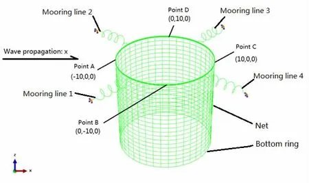
Fig.3 The complete fish cage system model

Tab.1 Properties of fish cage system
To begin with,the collar and bottom ring were simulated by the beam elements.Considering the non-bending properties of net twines,the truss elements were adopted to simulate the twines.
The instantaneous buoyancy acting on the collar often makes it difficult to calculate the hydrodynamic forces accurately.Therefore,the ‘Buoyancy Distribution’method,see Li[24],was adopted to solve this problem by replacing the partly immerged floating collar with 11 distributed coupled beams as shown in Fig.4.

Fig.4 Illustration of the distributed coupled beam section
The instantaneous buoyancy of the whole section fB_sectionequals the sum of the buoyancy of each immerged beamwhich can be expressed as:

In order to ensure that the distributed beam sections move and deform simultaneously,the six degrees of freedom for each pair of nearby nodes on the neighbouring beams should satisfy the linear constraints.
Meanwhile,the mass and bending-stiffness properties of the floating collar and the beams must also be equivalent,as described in the following equations:
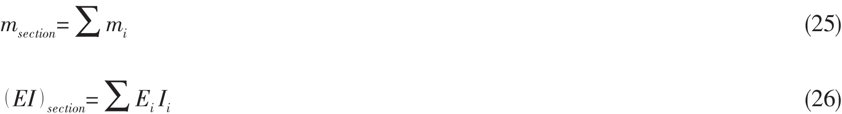
where msectionandE()Isectionare the mass density and the bending stiffness of the section in the floating collar,respectively,while miandE()Iiare the mass density and the bending stiffness of the ith distributed beam.
Secondly,in the simulation of the mooring lines,four spring elements with 6 000 N/m linear tensional stiffness,were employed.The spring elements were attached horizontally to the floating collar in the xoy plane in Fig.3.
3 Results and discussions
ABAQUS/Standard,a software for finite element analysis,was used to simulate the model under the combined effect of current and irregular waves.Both the wave load and the current load were calculated based on the Morison equations,the hydrodynamic coefficients CMand Cdshould be chosen according to the Re and KC numbers.In this paper,the Re number was pretty low and the KC number was very high,hence CMand Cdwere chosen as 2.0 and 1.2,respectively[25].Moreover,the geometrical nonlinearities associated with the nets’large deformation and motion were also taken into account.
3.1 Validation of the numerical model
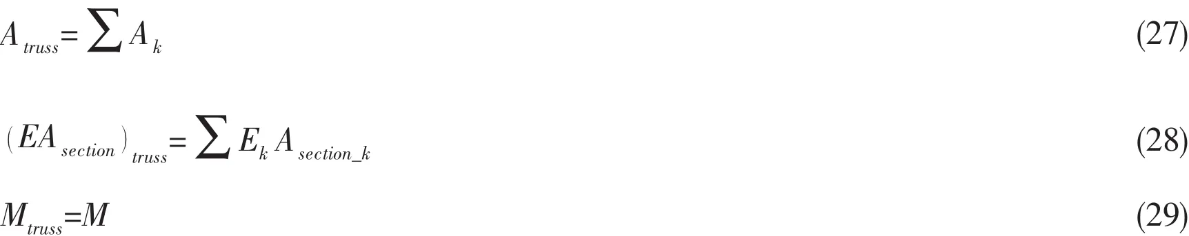
Owing to the large number of meshes in a full-scale net,it is hard to conduct calculations on a model with detailed mesh.Thus,the full-scale model was simplified.The hydrodynamic force,tensile stiffness and mass in the simplified model should be equivalent in the numerical models before and after simplification.This can be described in the following equations:where A and Asectionare the projected area and cross-sectional area of the twine;M is the mass of the net,and E represents the elastic modulus.Moe[19]validated their numerical models by comparing predicted deformation to that of a real model.Similar deformation to that observed by Moe[19]was observed in this model.Moreover,the deformation of the model with detailed mesh agrees well with that of the simplified model.The comparison also indicates that the model with coarse mesh was sufficiently accurate to study the motion and deformation of the gravity cage.The result is shown in Fig.5.

Fig.5 Validation and verification of the numerical model
3.2 Modal analysis of floating collar under combined effects of irregular waves and current
As the modal superposition method mentioned in the section 1.4,the mode shapes of the 1st to the 20th modes of the floating collar calculated by the modal analysis were shown in Fig.6.The modes numbered from 1 to 6 correspond to the six rigid-body-motion modes,while the rest correspond to the flexural deformation modes of the structure.In this analysis,the nonlinearities in the mooring-line are ignored.
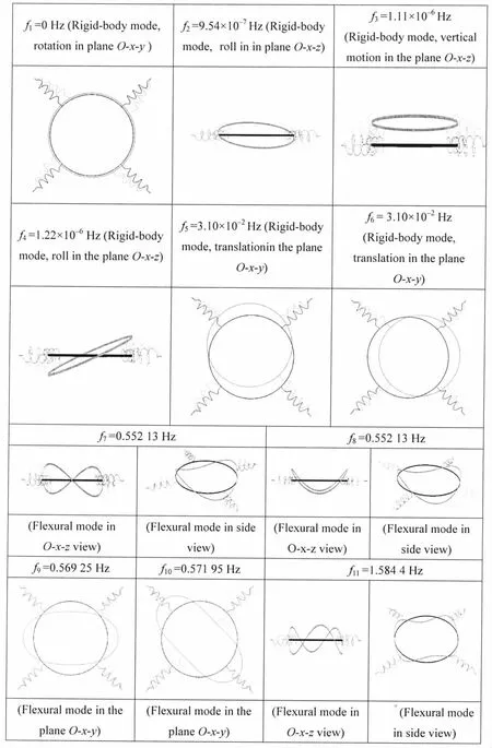
Fig.6 shows that the deformation of the 1st,5th,6th,9th,10th,13th,14th,17th and 18th modes appears in the O-x-y plane,while that of the 2nd,3rd,4th,7th,8th,11th,12th,15th,16th,19th and 20th modes occurs in the O-x-z plane in Fig.3.
In order to investigate the modal contribution,the numerical model operated in conditions where the current speed was set as 0 m/s,0.5 m/s and 1 m/s,coupled with irregular waves with significant heights set as 0.3 m,1 m and 3 m.Time histories of the modal weight in the horizontal and vertical directions are shown in the figures below(Figs.7-16),and their corresponding standard deviations are depicted in the four following figures(Figs.17-20):
Analysis of modal weights in the horizontal response revealed that the 5th,6th,9th and 14th modes were the dominant modes.This means that the translational rigid-body-motion modes as well as the in-plane flexural structural-deformation modes dominated the response of the floating collar.However,as the current speed increased,the modal weights of the 5th and 6th modes experienced a steeper increase than the flexural structural-deformation modes,indicating that the current had a stronger influence on the translational rigid-body-motion modes.

Fig.7 Modal weight(horizontal motion when H1/3=0.3 m,T1=5 s,C=0 m/s)
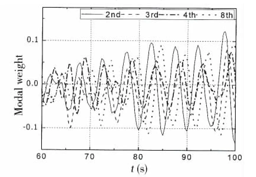
Fig.8 Modal weight(vertical motion when H1/3=0.3 m,T1=5 s,C=0 m/s)

Fig.9 Modal weight(horizontal motion when H1/3=1 m,T1=5 s,C=0 m/s)
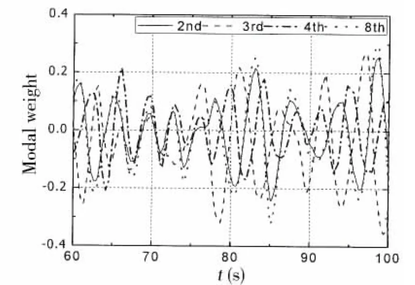
Fig.10 Modal weight(vertical motion when H1/3=1 m,T1=5 s,C=0 m/s)

Fig.11 Modal weight(horizontal motion when H1/3=3 m,T1=5 s,C=0 m/s)
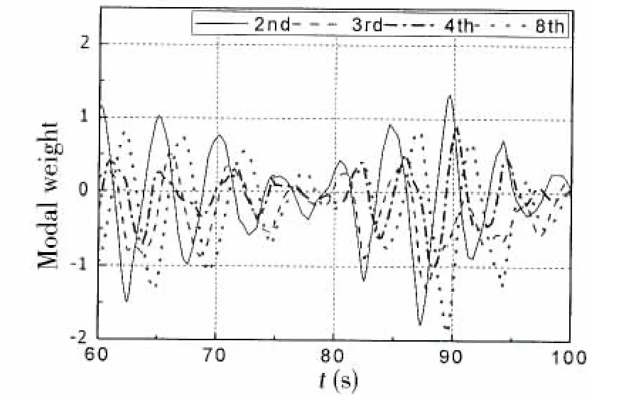
Fig.12 Modal weight(vertical motion when H1/3=3 m,T1=5 s,C=0 m/s)
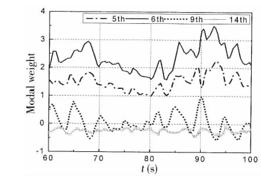
Fig.13 Modal weight(horizontal motion when H1/3=3 m,T1=5 s,C=0.5 m/s)
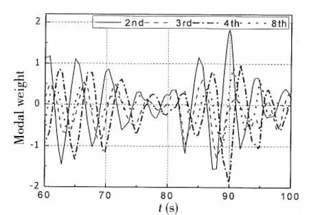
Fig.14 Modal weight(vertical motion when H1/3=3 m,T1=5 s,C=0.5 m/s)
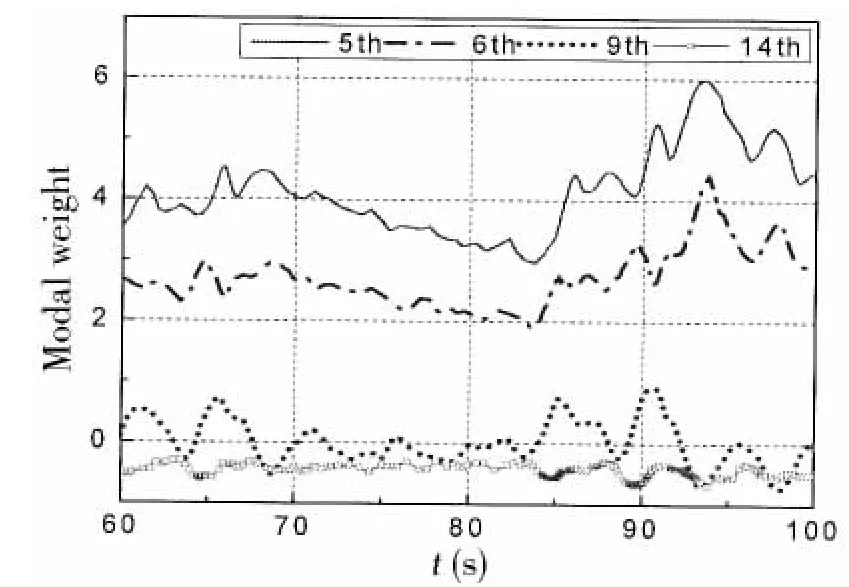
Fig.15 Modal weight(horizontal motion when H1/3=3 m,T1=5 s,C=1.0 m/s)
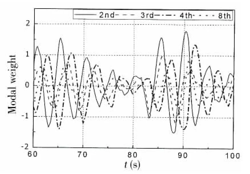
Fig.16 Modal weight(vertical motion when H1/3=3 m,T1=5 s,C=1.0 m/s)

Fig.17 Standard deviation of the horizontal response of each mode for different significant wave heights
With regard to the vertical response,the 2nd,3rd,4th and 8th modes participated most actively,as can be observed in Figs.8,10,12,14 and 16.Each modal weight increased with the significant wave height.On the other hand,Figs.12,14,and 16 show that the current had a smaller influence on the modal weight in the vertical direction compared to that in the horizontal direction.
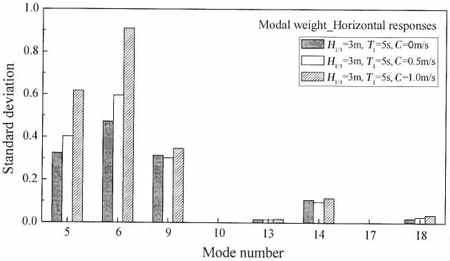
Fig.18 Standard deviation of the horizontal response of each mode for different current speeds
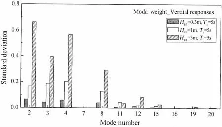
Fig.19 Standard deviation of the vertical response of each mode for different significant wave heights

Fig.20 Standard deviation of the vertical response of each mode for different current speeds
Besides,the comparison of the horizontal and vertical standard deviations of each mode above shows that much higher modes(flexural structural deformation modes)were excited vertically.The current had a stronger impact on the standard deviation of the 5th and 6th modes in the horizontal direction.In addition,the standard deviation of modal weight increased with significant wave height in both directions,which indicates that higher waves may induce higher order modes.
From the discussion in this section,it can be seen that compared with the wave-only-condition,the combination of current and wave has a greater influence on the translational rigidbody-motion in the horizontal direction.This indicates that the rigid-body motion of the floating collar should be paid more attention in the design of mooring systems attached to the fish cage in the wave and current combined condition.It has also been suggested that higher wave will arouse more flexible modes,while current contributes little to the flexible modes.
4 Conclusions
This paper presents an analysis based on the FEM in predicting the dynamic response of the gravity net cage system under the combined effects of irregular waves and current.The following conclusions are derived:the modal weight in both the horizontal and vertical directions becomes larger as the significant wave height increases,which can be found from the modal analysis of the floating collar under the combination of irregular wave and current.Meanwhile,the modal weight of the rigid-body-motion mode in the horizontal direction grows with the current speed,while the modal weight in the vertical direction is only slightly influenced by the variation of the speed.Moreover,it can be seen from the standard deviation of modal weight that much higher order modes will be excited with significant wave height increased.This indicates that when analyzing the total dynamic response under larger wave height,more attention should be paid on deformation.
[1]Lader P F,Olsen A,Jensen A,Sveen J K,Fredheim A,Enerhaug B.Experimental investigation of the interaction between waves and net structures-damping mechanism[J].Aquacultural Engineering,2007,37(2):100-114.
[2] Song W H,Liang Z L,Zhao F F,Huang L Y,Zhu L X.Approximate calculated on waving-force for a square sea-cage hydrodynamics[J].J Zhejiang Ocean Univ.,2003,23:211-220.(in Chinese)
[3]Ito S,Kinoshita T,Kitazawa D,Bao W,Itakura H,Nishizawa S.Experimental investigation and numerical modeling of hydrodynamic force characteristics of a heaving net[C].ASME,2010.
[4]Ito S,Kinoshita T,Kitazawa D,Bao W,Itakura H.Experimental investigation and numerical modeling of hydrodynamic force characteristics and deformation of an elastic net[C].ASME,2011.
[5]Krassimi I,Doynov.A dynamic response model for free floating horizontal cylinders subjected to waves[D].Doctoral dissertation,University of Florida,1998.
[6]Kristiansen David.Wave induced effects on floaters of aquaculture plants[D].Doctoral dissertation,Dept.of Marine Hydrodynamics,Norwegian Institute of Technology,2012.
[7]Colbourne D B,Allen J H.Observations on motions and loads in aquaculture cages from full scale and model scale measurements[J].Aquacultural Engineering,2001,24(2):129-148.
[8]Fredriksson D W.Open ocean fish cage and mooring system dynamics[D].Dept.Mechanical and Ocean Engineering,U-niversity of New Hampshire,2001.
[9]Fredriksson D W,Swift M R,Irish J D,Tsukrov I,Celikkol B.Fish cage and mooring system dynamics using physical and numerical models with field measurements[J].Aquacultural Engineering,2003,27:117-46.
[10]Fredriksson D W,DeCewa J,Swift M R,Tsukrov I,Chambers M D,Celikkol B.The design and analysis of a four-cage grid mooring for open ocean aquaculture[J].Aquacultural Engineering,2004,32:77-94.
[11]Dong G H,Xu T J,Zhao Y P,Li Y C,Gui F K.Numerical simulation of hydrodynamic behavior of gravity cage in irregular waves[J].Aquacultural Engineering,2010,42(2):90-101.
[12]Xu T J,Dong G H,Zhao Y P,Li Y C,Gui F K.Analysis of hydrodynamic behaviors of gravity net cage in irregular waves[J].Ocean Engineering,2011,38(13):1545-1554.
[13]Aarsnes J V,Rudi H,Løland G.Current forces on cage,net deflection[C]//Engineering for offshore fish farming.Proceedings of a conference organised by the Institution of Civil Engineers,17-18 October 1990.Glasgow,UK,Thomas Telford,1990:137-152.
[14]Lader P F,Enerhaug B.Experimental investigation of forces and geometry of a net cage in uniform flow[J].IEEE Journal of Oceanic Engineering,2005,30(1):79-84.
[15]Huang C C,Tang H J,Liu J Y.Dynamical analysis of net cage structures for marine aquaculture:Numerical simulation and model testing[J].Aquacultural Engineering,2006,35(3):258-270.
[16]Zhao Y P,Li Y C,Dong G H,Gui F K,Teng B.Numerical simulation of the effects of structure size ratio and mesh type on three-dimensional deformation of the fishing-net gravity cage in current[J].Aquacultural Engineering,2007,36(3):285-301.
[17]Zhao Y P,Li Y C,Dong G H,Gui F K,Teng B.The numerical simulation of hydrodynamic behaviors of gravity cage in current and waves[J].International Journal of Offshore and Polar Engineering,2009,19(1):97-107.
[18]Berstad A J,Tronstad H,Sivertsen S A,Leite E.Enhancement of design criteria for fish farm facilities including operations[C].ASME,2005.
[19]Moe H,Fredheim A,Hopperstad O S.Structural analysis of aquaculture net cages in current[J].Journal of Fluids and Structures,2010,26(3):503-516.
[20]Kristiansen T,Faltinsen O M.Modelling of current loads on aquaculture net cages[J].Journal of Fluids and Structures,2012,34:218-235.
[21]Faltinsen O.Sea loads on ships and offshore structures[M].Cambridge,UK:Cambridge University Press,1993.
[22]Lee C W,Kim Y B,Lee G H,Choe M Y,Lee M K,Koo K Y.Dynamic simulation of a fish cage system subjected to currents and waves[J].Ocean Engineering,2008,35(14):1521-1532.
[23]Lader P,Kristiansen D,Jensen O,Fredriksson D W.Experimental study on the interaction between the net and the weight system for a gravity type fish farm[C].ASME,2013.
[24]Li L,Fu S,Xu Y,Wang J,Yang J.Dynamic responses of floating fish cage in waves and current[J].Ocean Engineering,2013,72:297-303.
[25]Li L,Fu S,Xu Y.Nonlinear hydroelastic analysis of an aquaculture fish cage in irregular waves[J].Marine Structures,2013,34:56-73.

- 船舶力学的其它文章
- Numerical Study of the Shapes of the Super-Rogue Waves
- Application of Propagation Characteristics of Translating-Pulsating Source Green Function in the Side-Wall Effects Discrimination
- Study on Vulnerability Criteria and Model Experiment for Surf-Riding/Broaching
- LES Simulations of the Flow Around a Propeller in Crash Back and Crash Ahead
- Investigations on the Mechanical Behavior of an Innovative Subsurface Tension Leg Platform in Ultra-Deep Water(Part I)
- Low-Cycle Fatigue Crack-Propagation Behavior of Ship Cracked Plate Considering the Accumulative Plasticity under Variable Amplitude Loading