
Simulation of flow pattern at rectangular lateral intake with different dike and submerged vane scenarios
2017-11-20 05:25:21HojtKrmiSeedFrzinMohmmdTvkolSdrdiHsnMozeni
Water Science and Engineering 2017年3期
Hojt Krmi*,Seed FrzinMohmmd Tvkol Sdrdi,Hsn Mozeni
aFaculty of Civil Engineering,Semnan University,Semnan 351319111,Iran bSchool of Water Sciences Engineering,Shahid Chamran University of Ahvaz,Ahvaz 6135783151,Iran
Received 24 May 2016;accepted 16 March 2017 Available online 13 October 2017
Simulation of flow pattern at rectangular lateral intake with different dike and submerged vane scenarios
Hojat Karamia,*,Saeed Farzina,Mohammad Tavakol Sadrabadib,Hasan Moazenia
aFaculty of Civil Engineering,Semnan University,Semnan 351319111,IranbSchool of Water Sciences Engineering,Shahid Chamran University of Ahvaz,Ahvaz 6135783151,Iran
Received 24 May 2016;accepted 16 March 2017 Available online 13 October 2017
A comprehensive understanding of the sediment behavior at the entrance of diversion channels requires complete knowledge of threedimensional(3D) flow behavior around such structures.Dikes and submerged vanes are typical structures used to control sediment entrainment in the diversion channel.In this study,a 3D computational fluid dynamic(CFD)code was calibrated with experimental data and used to evaluate flow patterns,the diversion ratio of discharge,the strength of secondary flow,and dimensions of the vortex inside the channel in various dike and submerged vane installation scenarios.Results show that the diversion ratio of discharge in the diversion channel is dependent on the width of the flow separation plate in the main channel.A dike perpendicular to the flow with a narrowing ratio of 0.20 doubles the ratio of diverted discharge in addition to reducing suspended sediment input to the basin,compared with a no-dike situation,by creating the outer arch conditions.A further increase in the narrowing ratio decreases the diverted discharge.In addition,increasing the longitudinal distance between consecutive vanes(Ls)increases the velocity gradient between the vanes and leads to a more severe erosion of the bed,near the vanes.
©2017 Hohai University.Production and hosting by Elsevier B.V.This is an open access article under the CC BY-NC-ND license(http://creativecommons.org/licenses/by-nc-nd/4.0/).
Three-dimensional simulation;Computational fluid dynamics;Submerged vanes;Dike;Side and vortex flow
1.Introduction
Controlling sediment transport into diversion channels is one of the most challenging issues in river management.An understanding of the complex three-dimensional(3D)structure of flow and dynamics of sediment behavior at diversion entrances is essential to achieving predetermined objectives regarding diverted discharge,increased lifetime of the diversion channel,and reduction of sediment transport into the side channel.Various studies have been conducted on different aspects of side basins and the effects of changes in various parameters,including channel dimensions,divergence angles,and dewatering ratios.In addition,different structures have been used to control diverted discharge andsediment entrance into the basin,the most widely used being submerged vanes and dikes.Extensive studies have been performed to find parameters such as the optimal distance between consecutive vanes,the height and length of vanes and dikes,and the angles of flow impingement to vanes.There are ongoing studies on increasing the ef ficiency of these efforts by controlling the flow and sediment discharge through the diversion point.Kasthuri and Pundarikanthan(1987)studied dimensions of vortex and flow separation at the entrance of a 90°channel.Results showed that increasing the diversion ratio can reduce the length and width of the vortex area.They also showed that the length and width of the vortex area remain constant at diversion ratios greater than 0.7.Neary and Odgaard,1993 performed laboratory experiments on hydraulics of flow in a vertical lateral basin.They studied the changes in hydraulic parameters,such as the strength of secondary flow and the width of the flow separation plate in the main channel, finding that those parameters are dependent on the bed roughness and ratio of the flow velocity in a diversion channel to the flow velocity in the main channel.They also asserted that an explanation of the sedimentbehaviorata diversion entrance requiresa comprehensive understanding of 3D flow patterns around the lateral-channel entrance.In addition,they suggested that there is a strong similarity between flow in a channel bend and a diversion channel,and that this similarity can rationalize the use of bend flow models for estimation of 3D flow structures in diversion channels.Ouyang and Lu(2016)developed a methodology of estimating the optimal design of vane distribution along a channel bend,in order to protect the stream banks,based on the interaction between the river bank and a row of submerged vanes.Results indicated that the optimal distribution of vanes mainly depends on the radius of channel bends and the width of the channel,so that the relative radius of the bend has a signi ficant effect on the optimal distribution of vanes at sharp bends.Also,they inferred that the Froude number of sediment and the flow impingement angle to the vanes have less of an effect.In addition,Barkdoll et al.(1999)conducted studies on the limitations of application of submerged vanes to controlling sediment input to the basin.They showed that,with vanes placed at the diversion entrance,little sediment enters the basin as long as the diversion ratio of discharge is less than 0.2.Effectiveness of the vanes diminishes as the diversion ratio increases.They also suggested some methods of enhancing the performance of the vanes at higher diversion ratios,such as using skimming walls connected to submerged vanes and increasing the width of the side basin.In addition,they showed that other enhancements comprising modi fied shapes of vanes and increased velocity of flow into the side basin were not effective.Hassanpour et al.(2007)studied the effects of changes in the angle of submerged vanes with respect to flow on the diversion ratio and longitudinal flow surface pro file in the vicinity of a vertical diversion.They inferred that the optimal angle of vanes in both a subcritical and supercritical flow regime is equal to 20°.Gohari et al.(2010)studied simultaneous application of dikes and submerged vanes to controlling sediment input to basins,using dikes in three different dimensions and at the three different angles of 45°,90°,and 135°to the flow direction.Results showed that the dike must be located at a distance twice the width of the diversion channel prior to the basin entrance at an angle of 90°.Rostamabadi et al.(2013)used Taguchi methods to optimize geometrical indices of submerged vanes in a straight alluvial channel.They showed that the angle of the flow junction with the vane has the greatest impact on performance of the submerged vanes. Abbasi and MalekNejad(2014)investigated the effect of diversion angles of 45°,60°,75°,and 90°on the formation of vortex area.They showed that the dimensions of the vortex area in the diversion channel depend on the diversion ratio of discharge as well as the angle of diversion.Their results determined that increasing the diversion ratio decreases the length and width of the flow separation zone.Also,reducing the diversion angle increases the length and decreases the width of the recirculation area in the diversion channel.
Despite many experimental studies conducted on this topic,there is a lack of information on the features of sediment transport into diversion channels,and its dependence on flow patterns is evident.Numerical modeling is a logical and lowcost solution in this regard.Other advantages of numerical simulation include elimination of scale effects and more detailed analysis.However,experimental analysis cannot be replaced with numerical models.Many efforts have been made to enhance the accuracy and applicability of fluid dynamic solutions.Issa and Oliveira(1994)presented a numerical method of solving the 3D two-phase(air-water) flow at a rectangular T-junction.Their results showed that a pocket of high-concentration gas was formed at the entrance of the side channel,adjacent to the side wall.Tang et al.(2006)utilized large eddy simulations and the SIMPLEC algorithm to model the 3D flow patterns around a non-submerged spur dike.Wang et al.(2007)utilized a 3D numerical model to simulate the effects of bed discordance on the 3D flow structure at a symmetricrivercon fluence.Mahmodiniaetal.(2014)modeled flow patterns around submerged side weirs.They showed that decreasing the length of the side weir causes the separation zone to move downstream.They also found that changes in the length and over flow rate of the side weir have no signi ficant effect on the strength of secondary flow in the main channel.Ghiassi and Abbasnia(2013)used a numerical model to investigate the effects of vortices on the scouring and form of the alluvial channel bed.Ouyang and Lin(2016)developed an innovative numerical method to investigate the effects of vanes'shape on the formation of transverse bed pro files.They investigated three types of vane arrays and inferred that tapered vanes were the most effective.In addition,investigations on two vane systems determined that the two types of vanes were not equivalent in their effectiveness.Also,they concluded that the in fluence of the shape of vanes on the interaction effects is substantial when there is a small lateral space between the vanes.
Researchers have paid less attention to the simultaneous interaction between dikes and submerged vanes and their effect on flow features in the vicinity of diversion channels.Since the flow pattern has a direct in fluence on sediment transport to the diversions,further studies are required.Hence,this study intended to investigate the interaction between vanes and dikes of various dike lengths and different intervals between consecutive vanes.Transverse flow patterns induced by different designs of dike and vane installation as well as diversion ratios were investigated.Furthermore,characteristics of the recirculation area in the diversion channel and the width of the flow separation zone in the main channel were explored.
2.Materials and methods
In this study,the FLOW-3D numerical model was utilized as a solver of the Navier-Stokes equation to simulate 3D flow patterns at the entrance of a diversion channel.
2.1.Governing equations
Governing equations included the momentum and continuity equations.The continuity equation,regardless of the density of the fluid in the form of Cartesian coordinates x,y,and z,is as follows:
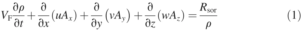
where u,v,and w represent the velocity components in the x,y,and z directions,respectively;Ax,Ay,and Azare the surface flow fractions in the x,y,and z directions,respectively;VFdenotes flow volume fraction;ρ is the density of the fluid;t is time;and Rsorrefers to the source of the mass.Eq.(2)shows momentum equations in three dimensions:

where Gx,Gy,and Gzare the accelerations caused by gravity in the x,y,and z directions,respectively;and fx,fy,and fzare the accelerations caused by viscosity in the x,y,and z directions,respectively.
2.2.Turbulence modeling
The turbulence models used in this study were the k-e,k-w,and k-ε renormalized group(RNG)models.Evaluation of the concordance of the mentioned models to laboratory experiments showed that the RNG model provides more accurate results.Hence,the main turbulence model used in this study was the k-ε(RNG)model.The k-ε model is a sophisticated and widely-used model consisting of two transport equations:one for turbulent kinetic energy k and the other for its dissipation ε(Harlow and Nakayama,1967).The 3D governing equationscan be expressed asfollows(Launderand Spaulding,1972):

where Gband Gkare generations of the turbulent kinetic energy due to buoyancy and mean velocity gradients,respectively;YMis the contribution of the fluctuating dilatation in compressible turbulence to the overall dissipation rate;C1ε,C2ε,C3ε,and Cμare constants(1.44,1.92,0.09,and 0.09,respectively); σkand σεare turbulent Prandtl numbers for k and ε(1.0 and 1.3,respectively);and μtis eddy viscosity.The RNG model uses equations analogous to the equations for the k-ε model.However,constants that are found empirically in the standard k-ε model are derived explicitly in the RNG model.Generally,the RNG model has wider applicability than the standard k-ε model.In particular,the RNG model is known to present more accurately for low-intensity turbulence flows and flows with strong shear regions(Yakhot and Smith,1992).
2.3.Boundary conditions and gridding
In this study,two blocks of meshes were used to simulate the main channels and diversion channels.The meshes were denser in the vicinity of the entrance of the diversion channel in order to increase the accuracy of computations.Boundary conditions for the main mesh block included in flow for the channel entrance,out flow for the channel end,walls for the bed and the right boundary,and symmetry for the top and left borders.Boundary conditions for the diversion channel included symmetry for the entrance and the top border,out flow for the exit,and walls for the rest.Considering the restrictions in the available processing power,a main mesh block with appropriate mesh size was de fined to simulate the main flow field in the channel,while the nested mesh-block technique was utilized to create a very dense solution field near the submerged vanes in order to provide accurate results among vanes and near the entrance of the diversion channel.This technique reduced the number of required mesh elements by up to 60%in comparison with the method in which the mesh size of the main solution field was decreased to the required extent.
2.4.Model veri fication
Veri fication of the model was performed using experimental data from Omidbeigi et al.(2012).The design of the laboratory flume is presented in Fig.1.
3D components of the velocity were predicted by three turbulence models,including the k-e,k-w,and RNG models,in different sections of the main channel and diversion channel with diversion ratios of 11%and 16%,respectively.Fig.2 compares the velocity pro files provided by numerical modeling and laboratory experiments.The results of error analysis are shown in Table 1.Laboratory measurements of velocity at x=4.73 m are compared to the results of numerical models in cases of 11%and 16%diversion ratios(Fig.3).The water depth in the main channel was kept constant(equal to 0.15 m)during all experiments.According to the results,the RNG turbulence model presents the most accurate results for the velocity field.
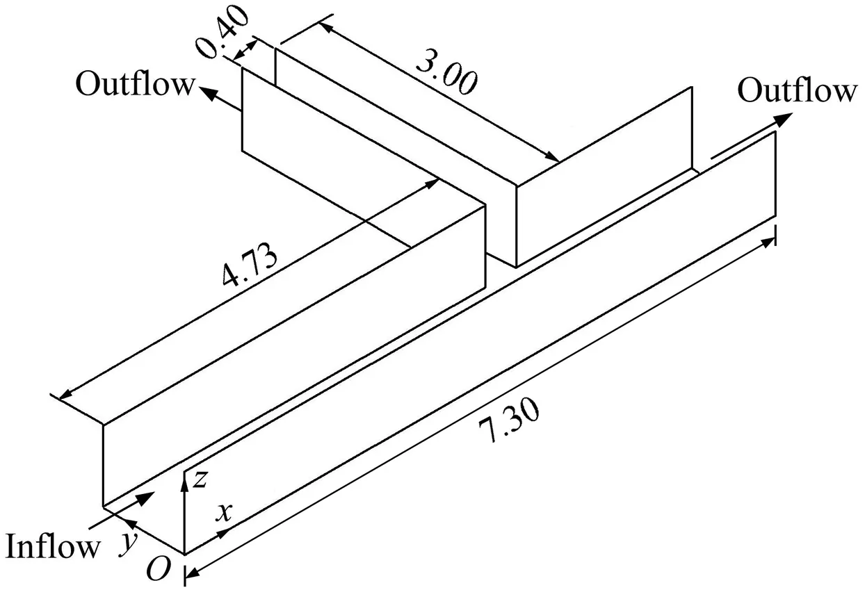
Fig.1.Dimensions of solution field used for validation of numerical model(units:m).
3.Scenarios of modeling
The solution field used in this study was a T-shaped intersection,which was constructed by connecting two direct channels with rectangular sections and rigid walls as shown in Fig.4.The length,width(Wc),and constant slope of the main channel were equal to 7.3 m,1m,and 0.002,respectively.The length and width of the diversion channel were equal to 3.0 m and 0.4 m,respectively.The dikes with lengths(Ld)of 0.20,0.25,and 0.30 mat an angle of 90°were located in the direction of flow,twice the width of the diversion channel prior to the entrance of the diversion channel(Abbasi and MalekNejad,2014).The height of the dike was considered to be equal to the height of the channel.Submerged vanes were placed in two rows;each consisted of six vanes.The vanes were placed at an angle of 20°with respect to the flow(Rostamabadi et al.,2013).The constant length and height(Hs)of the vanes were 9 cm and 3cm,respectively.The longitudinal spaces between the successive vane plates(Ls)in the three scenarios were 18 cm(Ls/Hs=6),24 cm(Ls/Hs=8),and 30 cm(Ls/Hs=10),respectively.Input discharge to the main channel had a fixed rate of 58L/s for all scenarios.Speci fications and dimensions of the dike and submerged vanes,with some calculated parameters including the diverted discharge(Qd),total discharge(Qt), flow velocity in the diversion channel(Vd),and flow velocity in the main channel(Vc)downstream of the diversion,are presented in Table 2 for all simulated scenarios.Fig.4 presents the plan of the main channel and diversion with dikes and submerged vanes.
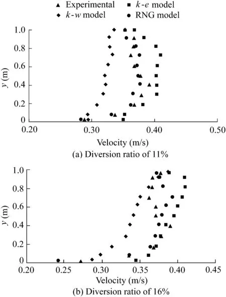
Fig.2.Comparison of velocity pro files provided by numerical modeling and laboratory experiments at z=0.09m and x=4.73 m.

Table 1 Comparison of turbulence models with error assessment criteria for diversion ratios of 11%and 16%.
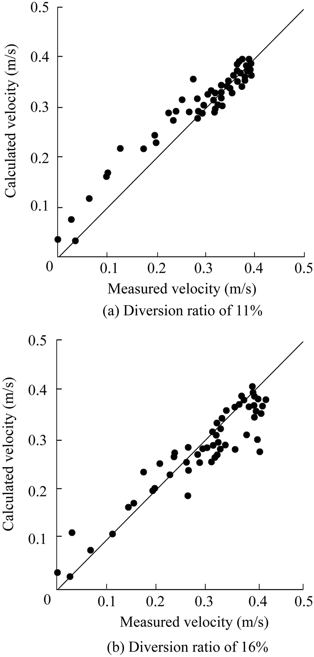
Fig.3.Comparison of experimental results of flow velocity with RNG model at z=0.09m.

Fig.4.Plan and dimensions of evaluated channel.
4.Results and analysis
4.1.Diversion ratio of discharge
As stated earlier,this study was intended to evaluate the effects of different distances between successive submerged vanes and the length of the dike in a 3D flow pattern.Table 2 presents the calculated diversion ratio of discharge with respect to the main discharge.Results indicated that installation of a 20 cm-long dike(Ld/Wc=0.20)upstream of an empty diversion increased the diverted discharge from the initial quantity of 11%(no dike and no vane)to 22.2%.Further increase in the length of the dike decreased the diverted discharge,so that the diversion ratio of discharge was reduced to 11.8%by increasing the length of the dike to 30 cm.This reduction in the diverted discharge was directly related to the increased flow velocity in the main channel,which resulted in reduction of the useful width of the diversion channel as well as the width of the flow separation zone(Wfs)in the main channel.
In the second step,installation of submerged vanes caused evident changes in the ratio of diverted discharge.Results indicated that,fora constantdike length (Ld),with Ld/Wc=0.20 and 0.25,increasing the distance between submerged vanes from 18 to 30 cm increased the diverted discharge.However,with Ld/Wc=0.30,the diverted discharge decreased with an increase in the space between the vanes.High velocity of flow reduced the useful width of the diversion channel,which largely reduced the diverted discharge at a narrowing ratio of 0.30.This is due to theformation of transverse vortices induced by the collision of high velocity of flow to the submerged vanes as well as the reduced width of the dividing stream plane towards diversion channel.Fig.5 shows that Wfssigni ficantly decreases(from 0.155 m to 0.079 m)as the narrowing ratio increases from 0.20 to 0.30.In other words,in the case without vanes,a 10%increase in the narrowing ratio of the main channel reduces the width of the flow separation zone by up to 50%.The reduction in the width of flow dividing stream surface is fully coordinated by reducing the ratio of the diverted discharge to the diversion channel.Considering the reduction in Wfs,it is expected that at any constant interval between the vanes(Ls/Hsis constant),the diversion ratio of discharge decreases as the length of the spur dike increases.However,installing the submerged vanes in the vicinity of the entrance of the diversion channel at Ls/Hs=6 and Ld/Wc=0.30 diverted larger amounts of water into the diversion channel.These changes in the ratio of diverted discharge showed that a combination of dikes and submerged vanes could be used to divert the desired discharge as well as to protect the entrance of the diversion channel from sediment transport.
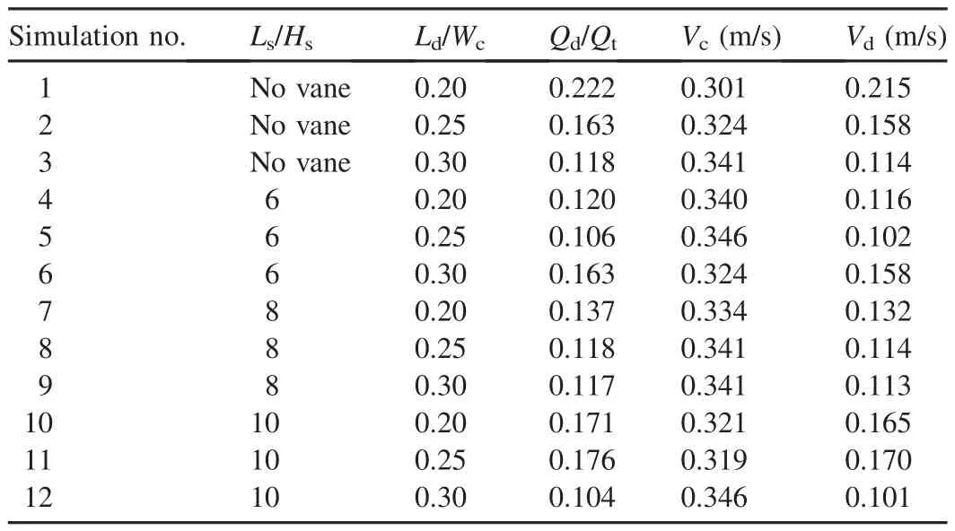
Table 2 Calculated parameters in various scenarios.
4.2.Strength of secondary flow in diversion channel
A spiral flow is formed in the diversion channel due to the presence of centrifugal force as well as the shear force caused by curvature of the stream lines(Neary et al.,1999).The spiral flow carries sediment from the river bed to the diversion channel.The strength of the secondary flow inside the channel canbe used toevaluate the strength of this phenomenon.Eq.(6)can be used to determine the strength of secondary flow:

where δ is the strength of secondary flow,Usis the transverse component of the velocity at the stream surface,and Ubis the transverse component of velocity at the bed of the diversion channel.To calculate this parameter,the transverse components of velocity at the bed and stream surface in the diversion channel at the coordinates of x=4.78 m and y=1.29 m were calculated for all simulated scenarios.
In general,it can be stated that,at a constant ratio of Ld/Wc,increasing the diversion ratio ampli fies the centrifugal force due to the momentum transfer to the diversion channel and the increase in the ratio of Vd/Vc,which consequently boosts the strength of the secondary flow in the diversion channel.It is clear that the submerged vanes affect the diverted discharge and flow pattern,which consequently affects the strength of the secondary flow.Table 3 shows changes in the dimensionless strength of the secondary flow(δ/U′)(U′is the average velocity in the main channel)in the diversion channel for different distances between the vanes with respect to various narrowing ratios of the main channel.The strength of the secondary flow in the diversion channel increases with the distance between submerged vanes when Ld/Wc=0.20 and 0.25,which is consistent with an increased diversion ratio of discharge.Also,the strength of the secondary flow decreases with a narrowing ratio of 0.30 as the ratio of Ls/Hsincreases.This is due to the reduction of entrained discharge into the diversion channel.The near-bed component of secondary flow circulation is the dominant process that affects the sediment entrainment into the separation zone.Hence,increasing the near-bed component of the transverse velocity is a means of increasing the sediment entrainment in the separation zone.
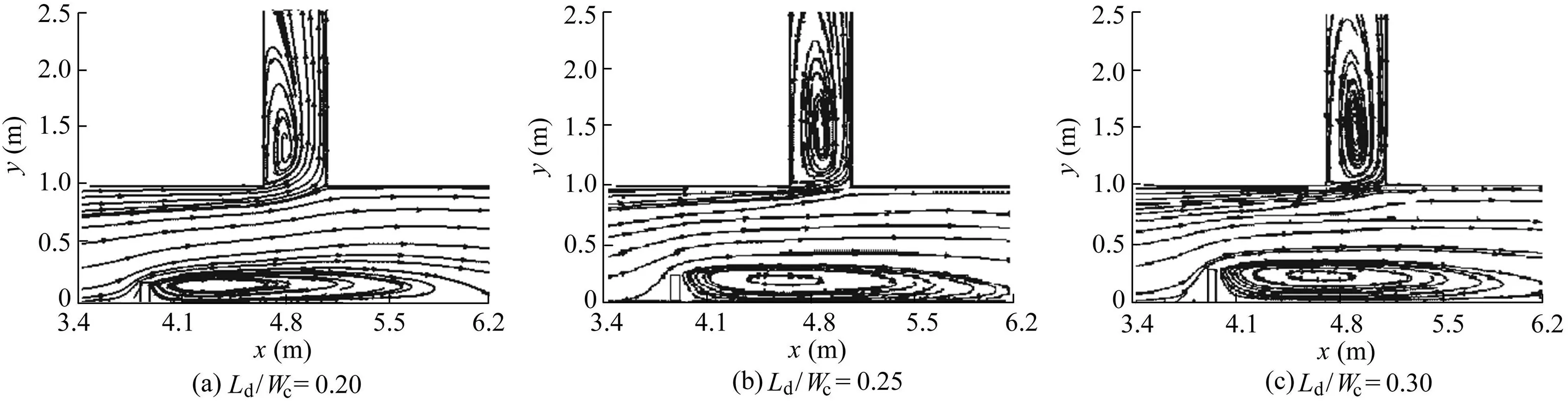
Fig.5.Dividing stream surface and vortex areas without vanes.
4.3.Dimensions of vortex area in diversion area
A major problem in the diversion channel lies in the blockage and reduced capacity of the channel due to sedimentation at the entrance of the diversion channel.Since sediments are deposited in the vortex area at the entrance of the diversion channel,the vortex area determines the useful width for the passage of flow.Therefore,it is essential to identify the vortex area known as the flow separation zone.
Fig.6 shows a schematic image of a vortex area in which Lvand Wvare the length and width of the vortex area,respectively.It must be noted that the dimensions of this area change with depth,so that the area is larger at the surface than near the bed.
Table 4 shows changes in the ratio of Wvto the width of the diversion channel(Wd)in different scenarios.It can be observed that the width of the vortex area continuously increases when Ld/Wc=0.30.In other words,the width of flow entrance to the diversion channel decreases and the width of the sedimentation area increases as the distance between submerged vanes increases.Also,when Ld/Wc=0.20,the width of the vortex area is largest for Ls/Hs=8.The changes in the length of the vortex area correspond more with changes in the diverted discharge.However,it is clear that the changes in Lshave a strong effect on the dimensions of the vortex areain the diversion channel and on the ratio of sediment entrainment in the diversion channel as well.
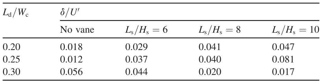
Table 3 Changes in dimensionless strength of secondary flow in various scenarios of dikes and submerged vanes.
4.4.Transverse patterns of flow in main channel
Flow lines in the main channel 5cm after the upstream wall of the entrance of the diversion channel(x=4.78m)are shown in Fig.7-9 in all scenarios.From Figs.7(b),(c),8(b),(c)and 9(b),(c),it can be inferred that larger and wider transverse vortex areas are observedwhen Ls/Hsis6 and8 for all the ratios when Ld/Wcis 0.20,0.25,and 0.30.It can be deduced that the strength of flow rotation caused by flow collision with submerged vanes decreases before arriving at the next vane due to the large distance between consecutive vanes with a ratio of Ls/Hs=10.Consequently,vortices are not formed,except between the vanes and behind the dike in the case of Ls/Hs=10.Thus,it can be concluded that sediments are deposited behind the dike and erosion occurs between the vanes.The vortex spreadsbetweenthevanesanddiverteddischargedecreaseswith an increasing narrowing ratio at Ls/Hs=10.Spreading of the vortex between the vanes can be associated with an increase in operating velocity in order to reduce the width of the flow separationzone,whichultimatelyreducesthediverteddischarge by increasing the narrowing ratio.

Fig.6.Schematic image of vortices formed in diversion channel and behind dike.

Table 4 Variations of size of vortex area in diversion channel in various scenarios of dikes and submerged vanes.
Vortices with complex flow patterns are formed at smaller distances between the vanes.In such cases,a flow pattern disrupts the existing trend in data series of diverted discharge and the strength of the secondary flow.In addition,this increases the risk of erosion and sedimentation and increases the erosion-susceptible areas.Moreover,changes in flow patterns in the main channel affect flow patterns in the diversion channel as well as dimensions of the vortex and flow separation zone.The angle of flow collision with submerged vanes is another important factor in formation of various flow patterns,which occurs between submerged vanes.This angle depends on the narrowing ratio(Ld/Wc)as well as the longitudinal distance between consecutive submerged vanes.Generally,the angle of flow collision with vanes and the flow velocity are dominant factors in the formation of longitudinal and transverse flow features.
Fig.10 presents the process of formation and development of vortices in the main channel from x=3.91 m(in the vicinity of the dike)to x=5.70 m with a narrowing ratio equal to 0.30(Ld/Wc=0.30)and Ls/Hs=10.Fig.10(a)shows the transverse flow feature induced by its collision with dike.After the narrowing section, flow collides with the first submerged vane after a short distance from the dike and a vortex is formed between the vanes.This vortex disappears as the discharge is diverted into the diversion channel(Fig.10(c))due to the large value of transverse velocity into the diversion channel.Vortices between the vanes re-form after the flow diversion and spread at the end of the channel entrance.This transverse vortex erodes the channel bed between vanes,endangers the stability of the vanes,and imports sediments to the diversion channel.
4.5.Width of flow separation zone in main channel
Generally,the dividing streamlines on a surface can be considered the dividing stream plane.This determines the portion of the main flow that is diverted to the diversion channel.The location of the streamline that divides the flow entering the diversion channel changes over depth so that more flow enters near the bed than near the surface.Hence,a larger portion of near-bed flow is diverted to the diversion channel in comparison with surface flow due to the higher momentum of surface flow.Also,the concentration of sediments is greater near the bed(Neary and Odgaard,1993).Therefore,the width of the flow separation zone in the main channel has an important effect on the amount of bed load entrainment in the diversion channel.Table 5 presents the ratio of the width of the flow separation zone to the free width of the main stream(Wc-Ld)in each scenario at x=4m.It is shown that the width of the flow separation zone increases as the narrowing ratio(Ld/Wc)increases.The smaller width of the flow separation zone with Ld/Wc=0.20 is closely related to the lower value of surface flow momentum.Results indicated that the width of the flow separation zone is mostly affected by the installation of submerged vanes,which affects the ratio of sediment entrainment in the diversion channel as well.The reduction in the width of the flow separation zone as well as the transverse flow patterns,shown in Figs.7-10,indicates that the ratio of sediment entrainment in the diversion channel will decrease effectively due to the installation of dikes and submerged vanes.Due to the effect of spiral flow in the main channel,which carries the bed load towards the diversion channel,it could not be inferred that the smaller ratio of width of flow separation zone represents a lower amount of sediment entrainment in the diversion.However,this study focused on dynamics of flow.Results of experimental study of the ratio of sediment entrainment in the diversion channel are still required in order to reach a clear understanding of the sediment dynamics.
4.6.Bed shear stress
Distribution of shear stress on the channel floor and areas prone to erosion and sedimentation are shown in Fig.11.Shear stress increases in the main channel toward the entrance of the diversion channel.A region with low shear stress exists on the opposite side of the entrance of the diversion channel,which is parallel to the stagnation zone and is prone to sedimentation.Sediments also accumulate in the vortex areas within the diversion channel and the vortex behind the dike in the main channel,as discussed in the previous sections.Furthermore,erosion occurs inside the channel in the flowing area due to the high velocity and circulation of secondary flows.A region with low shear stress prone to sedimentation is formed between the fourth and fifth columns of vanes.The flow deviates to the diversion channel in this area without forming a certain vortex as shown in Fig.11.
In addition,shear stress decreases in the main channel by moving away from the entrance of the diversion channel,due to the gradual weakness of secondary flows and decrease in the discharge and velocity in the main channel.
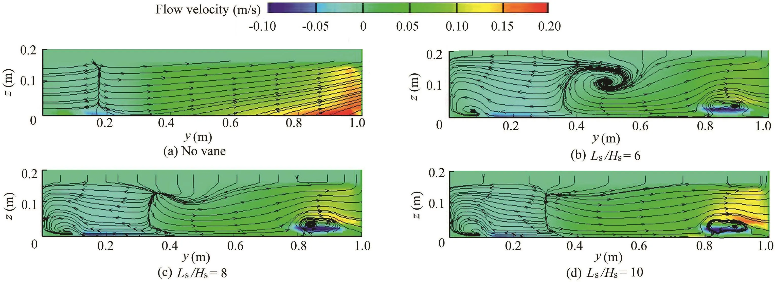
Fig.7.Transverse flow patterns at x=4.78m for Ld/Wc=0.20.
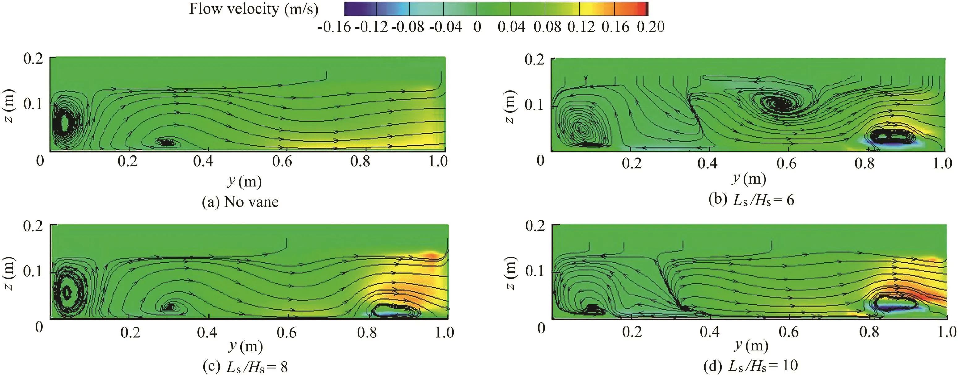
Fig.8.Transverse flow patterns at x=4.78m for Ld/Wc=0.25.
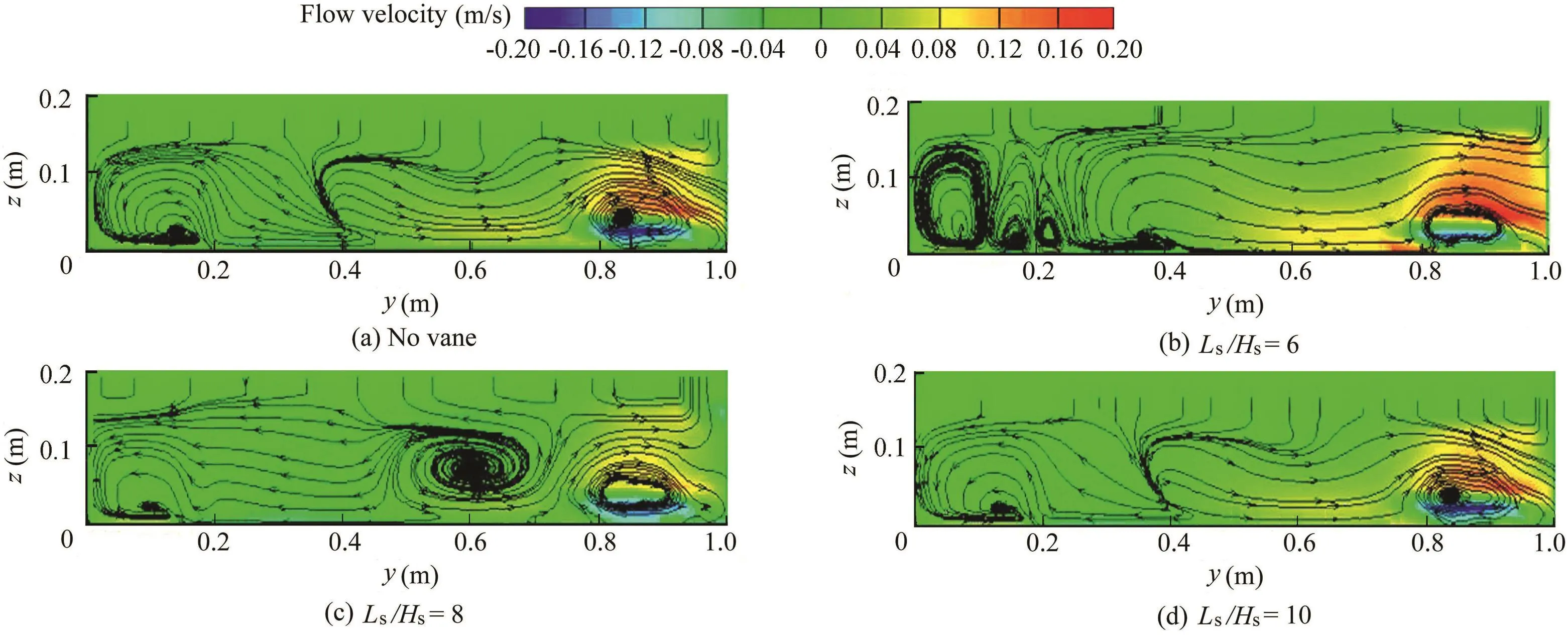
Fig.9.Transverse flow patterns at x=4.78m for Ld/Wc=0.30.
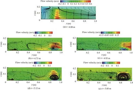
Fig.10.Transverse flow patterns in main channel for Ls/Hs=10 and Ld/Wc=0.30 in various sections.
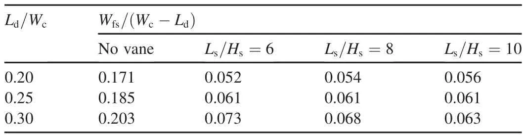
Table 5 Ratio of width of flow separation zone to free width of main stream in various scenarios at x=4m.
Fig.11 also shows that the maximum magnitude of shear stress occurs at the bottom left corner of the submerged vane,located in the third column of the first row of vanes,closer to the entrance of the diversion channel.Further investigation of streamwise flow velocity in the vicinity of submerged vanes indicates that increasing Lswill increase the magnitude of flow velocity between the vanes.A larger gradient of velocity around vanes is a sign of deeper scour holes around submerged vanes.Fig.12 presents the near-bed streamwise velocity distributions around submerged vanes and the entrance of the diversion channel with two ratios of Ls/Hsequal to 6 and 10.As stated above,increasing the distance between the vanes increases the shear stress and bed scouring between the vanes.

Fig.11.Shear stress distribution in main channel and diversion channel.
4.7.T-shape dike
Finally,a brief comparison between the T-shaped dike and simple dike was performed for Ld/Wc=0.25 and Ls/Hs=8 to investigate the effect of a T-shaped dike.The T-shaped dike consisted of two perpendicular sections,with lengths of 25 cm.The diversion ratio of discharge was equal to 13.6%in the T-shaped mode,which has increased by 2%compared to simple dike modes.The strength of secondary flow in a diversion channel increased by 20%.The width of the vortex area also increased by 10%,but the decrease in the length of the vortex was negligible.
5.Conclusions

Fig.12.Near-bed streamwise velocity distributions around submerged vanes with Ld/Wc=0.25.
This study examined the induced flow patterns around the entrance of a diversion channel due to the various lengths of dikes and longitudinal distance between submerged vanes and their probable effects on sediment entrainment in the diversion channel.Results indicated that a narrowing ratio of 0.20 in the main channel doubles the diverted discharge into the diversion channel and reduces the amount of sediment entrainment in the diversion channel.Increasing the narrowing ratio up to 0.30 may result in a reduction of the diverted discharge.This is due to the reduced width of the flow separation zone near the bed as well as formation of secondary circulation of flow in the main channel.For Ld/Wc=0.20 and 0.25,installation of submerged vanes with a ratio of Ls/Hs=6 reduces the amount of diverted discharge and increases the strength of secondary flow.With an increasing ratio of Ls/Hs,the diverted discharge increases.In various vane and dike scenarios,various discharges and strengths of secondary flows were recorded.There are optimum combinations of these structures,which divert necessary discharge and minimize erosion and sedimentation.Many factors are involved in development of flow patterns,including the flow velocity,bed roughness,and positions of obstacles such as dikes and vanes.Interactions between these factors create complex patterns of flow in different locations with various intensities.The different states of the structures affect the diverted discharges and the amount of erosion and sedimentation.They do so by affecting the flow velocity,creating or eliminating the vortices and controlling their dimensions,and controlling the width of the flow separation zone in the main channel.The strength of the secondary flow and dimensions of the vortex area in the diversion channel depend on the diversion ratio as well as the induced flow patterns in the main channel.Vortices that form between the vanes cause erosion and endanger their stability.A brief comparison of T-shaped and simple dikes showed that a T-shaped dike not only increases the diverted discharge,but also decreases dimensions of the vortex in the diversion channel.However,this is a worthwhile topic for future research.
Abbasi,A.A.,MalekNejad,M.,2014.The effect of threshold and submerged vanes on sedimentary flow input to side basin.J.Irrig.Water Eng.4(16),104-116(in Persian).
Barkdoll,B.D.,Ettema,R.,Odgaard,A.J.,1999.Sediment control at lateral diversions:Limits and enhancements to vane use.J.Hydraul.Eng.125(8),862-870.https://doi.org/10.1061/(ASCE)0733-9429(1999)125:8(862).
Ghiassi,R.,Abbasnia,A.H.,2013.Investigation of vorticity effects on local scouring.Arab.J.Sci.Eng.38(3),537-548.https://doi.org/10.1007/s13369-012-0337-8.
Gohari,S.,Ayoubzadeh,S.A.,Ghodsian,M.,Salehi Nishaboori,S.A.,2010.Laboratory experiment on flow pattern in side basins with simultaneous application of submerged vanes and dike in alluvial beds.J.Agric.Eng.Res.11(4),1-18(in Persian).
Harlow,F.H.,Nakayama,P.I.,1967.Turbulence transport equations.Phys.Fluids 10(11),2323-2332.https://doi.org/10.1063/1.1762039.
Hassanpour,F.,Ayoubzadeh,S.A.,Ghoddasian,M.,Vali Samani,G.M.,2007.Effect of submerged vanes on dewatering and longitudinal pro file of water level in vicinity of 90-degree side basins.J.Dev.Nat.Resour.77,104-114.
Issa,R.I.,Oliveira,P.J.,1994.Numerical prediction of phase separation in two-phase flow through T-junctions.Comput.Fluids 23(2),347-372.https://doi.org/10.1016/0045-7930(94)90045-0.
Kasthuri,B.,Pundarikanthan,N.V.,1987.Discussion of“Separation zone at open-channel junctions”by James L.Best and Ian Reid(November,1984).J.Hydraul.Eng.113(4),543-544.https://doi.org/10.1061/(ASCE)0733-9429(1987)113:4(543).
Launder,B.E.,Spaulding,D.B.,1972.Mathematical Models of Turbulence.Academic Press,London&New York.
Mahmodinia,S.,Javan,M.,Eghbalzadeh,A.,2014.The flow field and free surface pattern of the submerged side weir with different lengths.Arab.J.Sci.Eng.39(6),4461-4472.https://doi.org/10.1007/s13369-014-1058-y.
Neary,V.S.,Odgaard,A.J.,1993.Three-dimensional flow structure at openchannel diversions.J.Hydraul.Eng.119(11),1223-1230.https://doi.org/10.1061/(ASCE)0733-9429(1993)119:11(1223).
Neary,V.S.,Sotiropoulos,F.,Odgaard,A.J.,1999.Three-dimensional numerical model of lateral-intake in flows.J.Hydraul.Eng.125(2),126-140.https://doi.org/10.1061/(ASCE)0733-9429(1999)125:2(126).
Omidbeigi,M.A.,Ayyoubzadeh,S.A.,Safarzadeh Gendeshmin,A.,2012.Experimental and numerical study of three dimensional flow structure at lateral intake.Modares Civ.Eng.J.12(1),1-13(in Persian).
Ouyang,H.,Lu,C.,2016.Optimizing the spacing of submerged vanes across rivers for stream bank protection at channel bends.J.Hydraul.Eng.142(12).https://doi.org/10.1061/(ASCE)HY.1943-7900.0001210.
Ouyang,H.T.,Lin,C.P.,2016.Characteristics of interactions among a row of submerged vanes in various shapes.J.Hydro-environment Res.13,14-25.
Rostamabadi,M.,Salehi Neyshabouri,A.A.,Zarrati,A.R.,2013.Optimization of geometric parameters of submerged vane in straight alluvial channel with Taguchi method and GRA.Modares Civ.Eng.J.13(2),79-93(in Persian).
Tang,X.L.,Ding,X.,Chen,Z.C.,2006.Large eddy simulations of threedimensional flows around a spur dike.Tsinghua Sci.Technol.11(1),117-123.https://doi.org/10.1016/S1007-0214(06)70164-X.
Wang,X.G.,Yan,Z.M.,Guo,W.D.,2007.Three-dimensional simulation for effects of bed discordance on flow dynamics at Y-shaped open channel con fluences.J.Hydrodyn(Ser.B)19(5),587-593.https://doi.org/10.1016/S1001-6058(07)60157-7.
Yakhot,V.,Smith,L.M.,1992.The renormalization group,the ε-expansion and derivation of turbulence models.J.Sci.Comput.7(1),35-61.
*Corresponding author.
E-mail address:Hkarami@semnan.ac.ir(Hojat Karami).
Peer review under responsibility of Hohai University.
 Water Science and Engineering2017年3期
- Water Science and Engineering的其它文章
- Experimental and theoretical study of coupled in fluence of flow velocity increment and particle size on particle retention and release in porous media
- Flow patterns and critical criteria of thermally strati fied shear flow in braided rivers
- Fate of nitrogen in subsurface in filtration system for treating secondary ef fluent
- Application of SWAT99.2 to sensitivity analysis of water balance components in unique plots in a hilly region
- Assessment of future climate change impacts on hydrological behavior of Richmond River Catchment
- Numerical modeling of solute transport in deformable unsaturated layered soil