Plaque components affect wall stress in stented human carotid artery:A numerical study
Zhen-Min Fan·Xiao Liu·Cheng-Fei Du·An-Qiang Sun·Nan Zhang· Zhan-Ming Fan·Yu-Bo Fan·Xiao-Yan Deng
Plaque components affect wall stress in stented human carotid artery:A numerical study
Zhen-Min Fan1·Xiao Liu1·Cheng-Fei Du1·An-Qiang Sun1·Nan Zhang2· Zhan-Ming Fan2·Yu-Bo Fan1·Xiao-Yan Deng1
©The Chinese Society of Theoretical and Applied Mechanics;Institute of Mechanics,Chinese Academy of Sciences and Springer-Verlag Berlin Heidelberg 2016
Carotid artery stenting presents challenges of in-stent restenosis and late thrombosis,which are caused primarily by alterations in the mechanical environment of the artery after stent implantation.The present study constructed patient-specific carotid arterial bifurcation models with lipid pools and calcified components based on magnetic resonance imaging.We numerically analyzed the effects of multicomponent plaques on the distributions of von Mises stresses(VMSs)in the patient-specific models after stenting. The results showed that when a stent was deployed,the large soft lipid pool in atherosclerotic plaques cushioned the host artery and reduced the stress within the arterial wall;however,this resulted in a sharp increase of VMS in the fibrous cap.When compared with the lipid pool,the presence of the calcified components led to slightly increased stresses on the luminal surface.However,when a calcification was located close to the luminal surface of the host artery and the stenosis,the local VMS was elevated.Overall,compared with calcified components,large lipid pools severely damaged the host artery after stenting.Furthermore,damage due to the calcified component may depend on location.
Atherosclerosis·Plaque composition·Carotid artery stenting·Restenosis·Finite-element analysis
DOI 10.1007/s10409-016-0572-4
1 Introduction
The development of atherosclerotic plaques consisting of cells,lipids,calcium,collagen,and inflammatory infiltrates within the arterial wall leads to arterial stenosis,reduced blood flow,and myocardial infarction.Artery stenting is an effective and widely utilized therapy for atherosclerotic stenosis[1].However,this treatment faces late failure challenges resulting from in-stent restenosis and late thrombosis. According to clinical data,approximately 30%of patients with stents suffer from a renarrowing of the treated blood vessels over 6–12 months[2].
It is widely believed that vascular injury after stent implantation is a key cause of the formation of early occlusive intimal hyperplasia and eventually leads to restenosis.These vascular injuries are primarily attributed to alterations of the mechanical environment in the host artery owing to interactions of the deployed stent with the artery.The compressing force of the stent struts may wound the arterial wall,triggering vascular injury and stimulating the formation of intimal hyperplasia.A number of factors,such as stent configuration, artery geometry,and the deployment method,have been identified as affecting these interactions and,subsequently,local mechanical environmental changes[3,4].
The interactions between the stent and the host artery are also affected by the mechanical properties of the arterial wall[5].The wall mechanical properties can be very different among pathologically involved arteries due to varying wall compositions.Walsh et al.[6]and Teng et al.[7]studied these mechanical properties and found that the media,the fibrous cap,and the vessel were stiffer than lipids.Additionally,calcified samples have been shown to have the stiffest responses compared with echolucent and mixed samples[8]. Other studies have also demonstrated that the presence ofmixed plaques had significant impacts on local mechanical environments[9].Moreover,clinical studies have revealed obvious differences in outcomes after stent implantations for different types of plaque[2].We hypothesize that the mechanical environment of arteries having different compositions may vary dramatically after stenting and,hence, affect the outcomes of stenting therapy.We constructed several carotid multicomponent plaque models using magnetic resonance imaging(MRI)and numerically analyzed these models using a finite-element method in terms of the von Mises stress(VMS)distribution within the artery after stent deployment.
2 Materials and methods
2.1 Image-based carotid bifurcation artery and stent-balloon model
Because the plaque components in the MRI technique remain consistent with histological data,this technique has been widely developed to quantify the size,shape,and constituents of plaque[1,9].Hence,in this study,we applied the MRI technique to obtain the multicomponent carotid model.MRI images of 25 transverse slices of the left carotid artery were acquired from a 62-year-old patient.Each slice was captured by a 3T imager(Siemens Medical Solutions,Forchheim, Germany)at a 2mm thickness,a 512×512 pixel image size,and a 0.26mm pixel size.The patient provided written, informed consent to this study.The study was approved by the Ethical Committee of Beijing Anzhen Hospital and carried out in accordance with the regulations of the hospital.
The characterized plaque composition,lumen,and vessel wall morphology were obtained by comparing the T1,T2, and time-of-fight(TOF)images of the carotid atherosclerosis [9].The signal intensity of calcified tissue in plaque is weak (black color in Fig.1)in all MRI images.T1 images show the highest contrast in the calcification.Thus,to obtain more accurate contour plots of the calcification in this work,we segmented the calcification with T1 images referring to other series MRI images.The T2 images were suitable for characterizing lipid pools and outer boundaries,and the TOF images delineated the contour of the lumen.The plaque,lumen,and vessel were manually segmented by Mimics(Materialise, Leuven,Belgium).They were used to reconstruct a primitive three-dimensional(3D)model from which the centerline of the lumen was determined.The surface of the primitive model was smoothed to ensure that it was close to the real artery model and suitable for calculation.The carotid bifurcation was 50 mm in length,and there was a 69.5%diameter reduction at the narrowest region of the carotid.The plaque was 34.89mm in length.Figure 1 displays the model used in this study.

Fig.1 (Color online)Models used in this simulation.a One representative segmented slice of MRI images(TOF,T1,T2).b Reconstructed 3D artery model with different plaque components and three selected slices.c Stent-balloon model
A 3D design software,Pro/E(Parametric Technology Corporation,Massachusetts,USA),was used to construct a model of a commercial carotid stent,ViVEXX.This stent had an external diameter of 2.5 mm,a strut thickness of 81µm and a 25 mm length.Additional geometrical features of the stent have been described in previous works[10].The stent was bent and distorted along the centerline of the lumen for proper positioning in complex patient-specific geometries. Finally,the stent was assembled in the lumen along the lumen centerline.
2.2 Material properties
The carotid arterial wall and different plaque materials(e.g., lipid pools and calcifications)were assumed to be nonlinear,isotropic,and incompressible.These materials have been widely defined by the Mooney–Rivlin hyperelastic constitutive equation[4].The strain energy function is given by

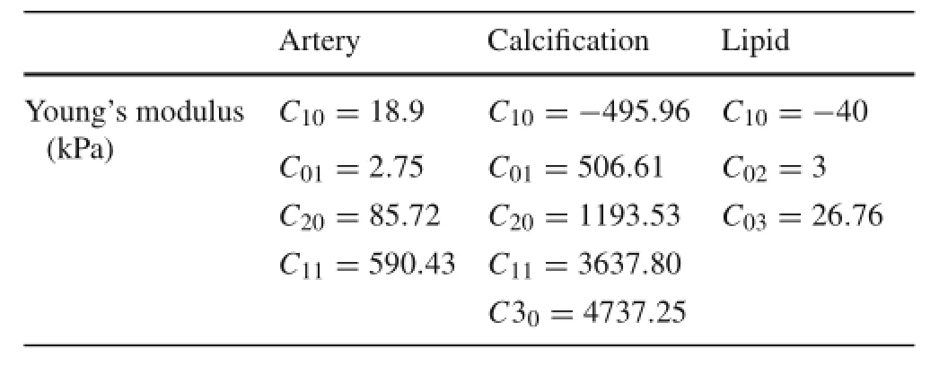
Table 1 Mechanical properties of carotid artery with plaques in finite-element model[6,7,11]
To investigate the influence of different plaque components on the local mechanical environment after stenting, simulations of the stenting procedure were prepared for the following models:
Model 1 served as a control wherein the arterial wall was assumed to be an isotropic and homogeneous material;
Model 2 was used to investigate the influence of a lipid pool on the local mechanical environment after stenting;this model was constructed with a lipid pool and an arterial wall;
Model 3 was used to investigate the role of calcification with only a calcified component and an arterial wall;
Model 4 was used to investigate a stented carotid artery with plaque components.
2.3 Finite-element analysis(FEA)of carotid artery stenting
To perform the stent deployment simulation,an artery-stent-balloon model was developed in the FEA software Abaqus/Explicit v.6.11(Dassault SIMULIARhode,Island, USA).An artery with plaques and a stent were meshed with 104870 and 212999 reduced eight-node brick elements (C3D8R),respectively.The balloon was discretized with 7072 reduced four-node shell elements(S4R).
Both ends of the vessel wall and balloon were assumed to be fully constrained.Several nodes at the distal side of the stent were fully constrained along the axial and circular directions,while several nodes on the other side of the stent were fixed along the axial direction[12,13].Additionally,a pressure of 1.01×10⁶Pa(10 atm)[12]was imposed on the inner surface of the balloon.The artery and plaques were grouped into a“multibody part”to permit node sharing.Interaction between stent and artery was defined as contact,which allowed relatively accurate movement.The surface-to-surface contact option in ABAQUS was used for the interaction of stent and artery.Frictionless contact was assumed for the other contact bodies[12].
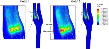
Fig.2 (Color online)Comparison of VMS distributions between Models 1 and 2.Model 1 contains plaques having the same material properties as a healthy artery.Model 2 was constructed with a lipid pool and healthy arterial wall
3 Results
To facilitate the presentation of the interactions between the stent and the artery,three representative slices were selected from the plaques(Fig.1).Slices A–C were perpendicular to the stenosis and transversed the plaques.Slice A was approximately located at the narrowest region,and Slices B and C were successively located at the back region of the stenosis.
3.1 Effect of large lipid pool
Figure 2 shows the distribution of the VMS on the stent-artery interaction surfaces in Models1 and 2.As shown in the figure, the large soft lipid pool significantly increased the VMS on the interaction surface.The VMS on the interaction surface was generally higher in Model 2 with the large lipid pool than in Model 1.The maximum VMS in Model 2 was higher than the control without multiple components(5.608×10⁶Pa vs.4.553×106Pa).Additionally,at the site of the stenosis, the VMS at the region close to the lipid pool in Model 2 was significantly greater than other regions in Model 2 and the corresponding region in Model 1.To further quantify the degree of vascular injury resulting from stenting between the two models,we calculated the averaged VMS value(VMS) on the area of the stent-artery interaction surfaces close to the stenoses(Fig.3a)in Models 1 and 2.As shown in Fig.3b, the 5.27×10⁶Pain Model 2 with a large lipid pool in the arterial wall was significantly greater than that of the control.
Figure 4a–f shows the distribution of the VMS in the arterial wall.When compared with Model 1,the VMS in Model 2 with a lipid pool was unevenly distributed with a relatively low stress in the lipid pool and a high stress concentration between the lipid pool and the vascular lumen,i.e.,the fibrous cap region.Therefore,the large soft lipid pool reduced the stress within the arterial wall of the host artery but sharply increased the VMS in the fibrous cap.
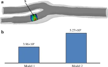
Fig.3 a Stent-artery interaction surface close to stenosis(S).b Average values ofon S in Models 1 and 2
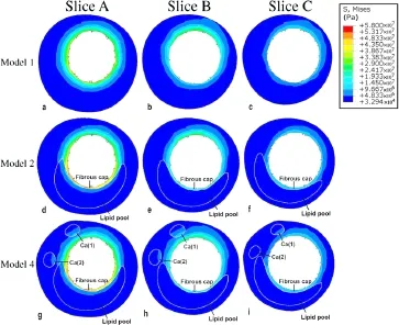
Fig.4 (Color online)Distribution of VMS in Models1,2,and 4 for the three representative slices shown in Fig.1.Model 1 contained plaques having the same material properties as a healthy artery;Model 2 was constructed with a lipid pool and healthy arterial wall;Model4 contains all plaque components
3.2 Effect of calcified component
Figure 5 shows the VMS in the calcified region after the stenting simulations in Models 1 and 3.For both models,the VMS in the calcified region close to the stent was relatively higher vs.the farther region.However,when compared with Model 1,the VMS in the artery with calcification(Model 3) was significantly higher.The maximum VMS in Models 1 and 3 were 9.32×10⁵and 2.39×10⁶Pa,respectively.
To determine the influence of the location of the calcification,the VMS of three slices in Model 3 are shown in Fig.6. The VMS of a calcified component adjacent to the luminal surface[Ca(1)]was higher than that of a calcified component relatively far from the luminal surface[Ca(2)].The VMS for both calcified components decreased as the distance to the luminal surface increased in the longitudinal direction.Additionally,compared with other slices,the value of the VMS for most calcified regions in Slices A and B,which were close to the stenosis,were relatively higher than the VMS of the calcified region in Slice C.
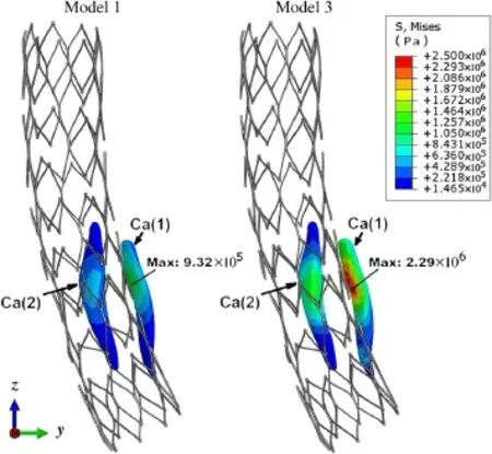
Fig.5 (Color online)Comparison of VMS distributions in calcified regions between Models 1 and 3.Model1 contained plaques having the same material properties as a healthy artery.Model 3 was constructed with only the calcified component and healthy arterial wall

Fig.6 (Color online)View of VMS field in Model 3 for the three representative slices shown in Fig.1.Model 3 was constructed with only the calcified component and healthy arterial wall
3.3 Combined effect of different plaque components
Figure 4g–i shows the VMS distributions for Model 4 with intact plaque material properties.Compared with Model 1, the presence of the lipid pool and calcified component resulted in a higher VMS in the arterial wall and on the luminal surface.This phenomenon was especially apparent in the fibrous cap,where the stress concentration induced by the presence of the lipid pool was quite severe.
4 Discussion and conclusion
The failure of stenting therapies due to restenosis and late thrombosis remains an issue.Studies have attributed this problem primarily to vascular injuries after stent implantationresulting from interactions between the host artery and the stent.In past years,the interactions between the stent and the artery were extensively investigated with numerical simulation.However,most of these studies[11,13]used limited or idealized models with atherosclerotic plaques having nonrealistic geometrical configurations and simplified mechanical properties.While a few recent studies[4]used patient-specific parameters to analyze these interactions,they did not consider the varying mechanical property of atherosclerotic plaques.However,the studies that used patient-specific models found that mechanical stress distributions were sensitive to the configuration and mechanical properties of the stents involved.In addition to these stent characteristics,we also consider the configuration and mechanical properties of atherosclerotic plaques to be crucially important.To clarify the roles of different atherosclerotic plaque components in a pathological artery,we obtained images of a human pathological carotid artery with multicomponent plaques using MRI. We numerically analyzed the distributions of VMSs for stents deployed in our models and compared the results of models having different components of plaque in terms of the VMS distributions.
Our results showed that when a stent was deployed,a large soft lipid pool in the atherosclerotic plaque cushioned the host artery and reduced the stress within the arterial wall(Fig.4) and further resulted in a sharp increase in the VMS(stress concentration)in the fibrous cap.This indicated that when an atherosclerotic plaque has a large lipid pool,its fibrous cap may suffer greater damage after a stenting procedure. The fragmentation of the fibrous cap within the endothelium will likely amplify the inflammatory reaction and increase the risk of restenosis.Our numerical results were consistent with findings from clinical studies that determined positive correlations between late thromboses and atherosclerotic plaques with large lipid pools[5,14].Moreover,a study by Gao and Long[15]demonstrated that the volume of the lipid pool and the thickness of the fibrous cap were correlated with plaque stability.
However,the role of calcified components in these symptomatic events remains controversial.A few studies[5] have suggested that the calcified components of a plaque play positive roles in maintaining plaque stability after the stenting procedure.Other studies have shown contradictory evidence,reporting that calcification was an important predictor of adverse outcomes[16,17].Still other studies[18,19] have found no direct relationships between calcifications and adverse outcomes.In this study,our numerical models suggested that,compared with large lipid pools,the presence of calcified components leads to slightly increased stresses on the luminal surface of arterial walls.This may suggest that the calcification of atherosclerotic plaques in these models is less important in terms of affecting stress distribution.However,our results also indicated that when a calcification was located close to the luminal surface of the host artery and the stenosis,the calcification could elevate the local VMS (Fig.6).This suggests that the effect of a calcified component on a stenting procedure may depend on the location of the calcification.
We numerically investigated the mechanical responses of a human carotid artery with atherosclerotic plaques after stenting in terms of the VMS distribution to clarify the roles of different plaque components in possible outcomes of stenting therapy.The results showed that a stenting procedure subjected fibrous caps with large lipid pools to abnormally high VMSs and further promoted the development of restenosis.We also found that the calcified components of the artery provided lower risks due to the relatively lower local VMS. However,the role of calcified components on the outcome of a stenting procedure may depend on the calcification location.These results indicated that stenting in a clinical setting should be based on plaque features.In this way,the optimized mechanical environment in the host artery will be established,making it possible to promote reendothelialization and inhibit restenosis after stent implantation.
Acknowledgments This work is supported by the National Natural Science Foundation of China(Grants 11332003,11421202,61190123, 31200703,11472031);Special Fund for Excellent Doctoral Degree Dissertation of Beijing(Grant 20131000601);the 111 Project(Grant B13003);the Innovation Foundation of BUAA for Ph.D.graduates.
References
1.Bentzon,J.F.,Otsuka,F.,Virmani,R.,et al.:Mechanisms of plaque formation and rupture.Circ.Res.114,1852–1866(2014)
2.von Birgelen,C.,Mintz,G.S.,Eggebrecht,H.,et al.:Preintervention arterial remodeling affects vessel stretch and plaque extrusion during coronary stent deployment as demonstrated by three-dimensional intravascular ultrasound.Am.J.Cardiol.92, 130–135(2003)
3.Chen,Z.S.,Fan,Z.M.,Zhang,X.W.:The interactions between bloodstream and vascular structure on aortic dissecting aneurysmal model:A numerical study.Acta Mech.Sin.29,462–468(2013)
4.Morlacchi,S.,Colleoni,S.G.,Cardenes,R.C.,et al.:Patientspecific simulations of stenting procedures in coronary bifurcations:Two clinical cases.Med.Eng.Phys.35,1272–1281(2013)
5.Sonoda,S.,Muraoka,Y.,Kashiyama,K.,et al.:Coronary arterial remodeling and peristent plaque change after drug-eluting stent implantation:comparison between zotarolimus-eluting stents and paclitaxel-eluting stents.J.Am.Coll.Cardiol.59,E147–E147 (2012)
6.Walsh,M.T.,Cunnane,E.M.,Mulvihill,J.J.,etal.:Uniaxial tensile testing approaches for characterisation of atherosclerotic plaques. J.Biomech.47,793–804(2014)
7.Teng,Z.Z.,Zhang,Y.X.,Huang,Y.,et al.:Material properties of components in human carotid atherosclerotic plaques:A uniaxial extension study.Acta Biomater.10,5055–5063(2014)
8.Chai,C.K.,Speelman,L.,Oomens,C.W.J.,et al.:Compressive mechanical properties of atherosclerotic plaques-indentation test to characterise the local anisotropic behaviour.J.Biomech.47, 784–792(2014)
9.Tang,D.L.,Yang,C.,Zheng,J.,et al.:3D MRI-based multicomponent FSI models for atherosclerotic plaques.Ann.Biomed.Eng. 32,947–960(2004)
10.Carnelli,D.,Pennati,G.,Villa,T.,et al.:Mechanical properties of open-cell,self-expandable shape memory alloy carotid stents. Artif.Organs 35,74–80(2011)
11.Pericevic,I.,Lally,C.,Toner,D.,et al.:The influence of plaque composition on underlying arterial wall stress during stent expansion:The case for lesion-specific stents.Med.Eng.Phys.31, 428–433(2009)
12.Gastaldi,D.,Morlacchi,S.,Nichetti,R.,et al.:Modelling of the provisional side-branch stenting approach for the treatment of atherosclerotic coronary bifurcations:effects of stent positioning. Biomech.Model.Mechanobiol.9,551–561(2010)
13.Liang,D.K.,Yang,D.Z.,Qi,M.,et al.:Finite element analysis of the implantation of a balloon-expandable stent in a stenosed artery. Int.J.Cardiol.104,314–318(2005)
14.Wong,K.K.L.,Thavornpattanapong,P.,Cheung,S.C.P.:Effect of calcification on the mechanical stability of plaque based on a three dimensional carotid bifurcation model.BMC Cardiovasc.Disord. 12,1–18(2012)
15.Gao,H.,Long,Q.:Effects of varied lipid core volume and fibrous cap thickness on stress distribution in carotid arterial plaques.J. Biomech.41,3053–3059(2008)
16.Tang,D.L.,Yang,C.,Zheng,J.,et al.:Image-based modeling and precision medicine:patient-specific carotid and coronary plaque assessment and predictions.IEEE Trans.Biomed.Eng.60,643–651(2013)
17.Teng,Z.Z.,He,J.,Sadat,U.,et al.:How does juxtaluminal calcium affect critical mechanical conditions in carotid atherosclerotic plaque?An exploratory study.IEEE Trans.Biomed.Eng.61,35–40(2014)
18.Gray,W.A.,Yadav,J.S.,Verta,P.,et al.:The CAPTURE registry: Predictors of outcomes in carotid artery stenting with embolic protection for high surgical risk patients in the early post-approval setting.Catheter.Cardiovasc.Interv.70,1025–1033(2007)
19.Tsutsumi,M.,Kodama,T.,Aikawa,H.,et al.:Fragmentation of calcified plaque after carotid artery stenting in heavily calcified circumferential stenosis.Neuroradiology 52,831–836(2010)
✉ Xiao Liu liuxiao@buaa.edu.cn
✉ Xiao-Yan Deng dengxy1953@buaa.edu.cn
1School of Biological Science and Medical Engineering, Beihang University,Beijing 100191,China
2Radiologic Department,Beijing Anzhen Hospital,Capital Medical University,Beijing 100029,China
21 February 2016/Revised:31 March 2016/Accepted:11 April 2016/Published online:7 September 2016
- Acta Mechanica Sinica的其它文章
- Closed-form solutions for free vibration of rectangular FGM thin plates resting on elastic foundation
- MoM-based topology optimization method for planar metallic antenna design
- Dilation and breakage dissipation of granular soils subjected to monotonic loading
- A semi-analytical approach for calculating the equilibrium structure and radial breathing mode frequency of single-walled carbon nanotubes
- Thermoelastic analysis of multiple defects with the extended finite element method
- Time-delay identification for vibration systems with multiple feedback

