Thermoelastic analysis of multiple defects with the extended finite element method
Honggang Jia·Yufeng Nie
Thermoelastic analysis of multiple defects with the extended finite element method
Honggang Jia1·Yufeng Nie2
©The Chinese Society of Theoretical and Applied Mechanics;Institute of Mechanics,Chinese Academy of Sciences and Springer-Verlag Berlin Heidelberg 2016
In this paper,the extended finite element method (XFEM)is adopted to analyze the interaction between a single macroscopic inclusion and a single macroscopic crack as well as that between multiple macroscopic or microscopic defects under thermal/mechanical load.The effects of different shapes of multiple inclusions on the material thermomechanical response are investigated,and the level set method is coupled with XFEM to analyze the interaction of multiple defects.Further,the discretized extended finite element approximations in relation to thermoelastic problems of multiple defects under displacement or temperature field are given.Also,the interfaces of cracks or materials are represented by level set functions,which allow the mesh assignment not to conform to crack or material interfaces. Moreover,stress intensity factors of cracks are obtained by the interaction integral method or the M-integral method,and the stress/strain/stiffness fields are simulated in the case of multiple cracks or multiple inclusions.Finally,some numerical examples are provided to demonstrate the accuracy of our proposed method.
Multiple defects·Stress intensity factors· extended finite element method(XFEM)·Thermoelastic
DOI 10.1007/s10409-016-0598-7
1 Introduction
Recently,the importance of multiple defects in materials has attracted increasing attention all over the world because of their help in understanding the strengthening and toughening mechanisms,as well as the fracture mechanism for orthotropic composite materials or anisotropic composite materials.Currently,related studies are mainly performed by various analytic or numerical methods,such as the body force method[1],the complex function method[2],the boundary element method[3],the dislocation method[4],the finite element method[5],the extended finite element method (XFEM)[6],and the interaction integral method[7].Among these,several papers have simulated the interaction between multiple defects under thermal and/or mechanical load using XFEM.For example,Yu et al.[7]studied the mixed-mode stress intensity factors(SIFs)for a single crack and a single inclusion in nonhomogeneous materials using the interaction integral method.In addition,Chopp and Sukumar[8] simulated the fatigue crack propagation of multiple coplanar cracks using the coupled extended finite element/fast marching method.Also,Daux et al.[9]simulated arbitrarily branched and intersecting cracks with XFEM.Then too, Budyn et al.[10]proposed a method for multiple crack growth in brittle materials using XFEM.In addition,Loehnert and Belytschko[11]researched the effects of crack shielding and amplification caused by various arrangements of micro-cracks on the SIFs of a macrocrack;Sutula[12]proposed the global energy minimization for multiple fracture growth.Furthermore,Natarajan et al.[13]studied the effects of local defects,i.e.,cracks and cutouts,on the buckling behaviors of functionally graded material plates subjected to mechanical and thermal loading.Also,Sundararajan et al.[14]presented a new numerical integration technique,which can be used in XFEM,for arbitrary polygonal domains based on Schwarz–Christoffel conformal mapping.So then, Cahill et al.[15]adopted an enriched finite element method to simulate the growth of cracks in linear elastic aerospace composite materials.Work done by Stéphane et al.[16]simulated two-dimensional(2-D)linear elastic fracture mechanics for hundreds of cracks with local near-tip refinement,2-D crack propagation problems,and complicated three-dimensional (3-D)industrial problems.To sum up,although plenty of papers have addressed numerical analysis about this problem, up to now,few reported papers adopt XFEM to solve the interaction between multiple cracks and multiple inclusions under thermal/mechanical load[17,18].XFEM has some advantages over the abovementioned methods for solving complex geometry and general discontinuous problems.For example, the body force method is usually used in special interactions between cracks and inclusions;the usual numerical method such as the finite element method requires the meshing should conform to crack or material interfaces.By contrast,XFEM can mesh an arbitrary number of cracks or inclusions in various types,which provides great convenience for numerical simulation.In this paper,we present the modeling of internal boundaries by coupling the level set method with XFEM[19].In XFEM,the elements that incorporate singularity points are handled by adding crack enriched functions. XFEM can be used to deal with these discontinuity problems[20],implicit interface problems[21],hole or inclusion problems[11],thermal/mechanical fracture problems[22–27],etc.The level set method can be used to model moving discontinuities,such as material interfaces(holes or inclusions)or cracks[28].Usually,the interfaces of inclusions or crack surfaces are represented by the level set function.
The interaction integral method is a robust and accurate post-processing technique,which can be combined with XFEM to evaluate the mixed-mode SIFs[29,30].Then Yau et al.[29]used the interaction integral method for two admissible states,the actual state and an auxiliary one,to evaluate SIFs in homogeneous isotropic materials.Furthermore,Wang et al.extended the method to homogeneous orthotropic materials.In addition,Yau et al.[29]also used the method to analyze bimaterial interface problems.Recently, this interaction integral method has been used for evaluating SIFs in isotropic/anisotropic thermoelastic fracture problems,e.g.,a plane crack problem of nonhomogeneous materials with interfaces subjected to static thermal loading [30].
The rest of this paper is organized as follows.In Sect.2, starting with the problem statement of the interaction between a single crack and a single inclusion,the related governing equations are presented.Then,Sect.3 gives a brief introduction to XFEM and the discretized thermoelastic finite element formulation,and provides XFEM implementation for multiple cracks and multiple inclusions.Section 4 recalls the level set method.Section 5 addresses the interaction integral method for a thermoelastic crack problem.In Sect.6, some numerical examples are presented to demonstrate the accuracy of the new technique.Finally,some concluding remarks are given in Sect.7.
2 Problem statement for the interaction between a single crack and a single inclusion and governing equations for thermoelastic problem of multiple defects
The interaction between a single crack and a single inclusion under mechanical or thermal load is investigated in this paper by using XFEM.Figure 1 shows the geometry of the problem(see detail in Ref.[1]).Material 1 is an isotropic homogeneous matrix material with a shear modulus of G1and a Poisson ratio of ν1,and it occupies the outer infinite region Ω1.Material 2 is an isotropic homogeneous inclusion with a shear modulus of G2and a Poisson ratio of ν2,and it occupies the inner round region Ω2with a radius of R. Here,the interface between the inclusion and the matrix is assumed to be perfectly bonded.A straight adiabatic crack with a length of 2l is embedded in the matrix with uniform remote stress and thermal loads(uniform temperature field load).The distance between the crack tip A and the boundary of the inclusion is d=OA−R.The angle between the crack line and the X axis is θ.
Assuming the crack face[31]or inclusion face is traction-free and adiabatic,then the field equations of thermoelastodynamics are:

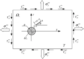
Fig.1 A crack in the neighborhood of an inclusion under thermomechanical load(see Ref.[1])

where ε is the strain tensor,∇sis the symmetric gradient operator on a vector,u is the field displacement,εTis the thermal expansion,γ is the expansion coefficient,ΔT is the change of temperature I is the identity second-order tensor, σ is the stress tensor,C is the isotropic Hooke tensor,q is the thermal flux,K is the thermal conductivity matrix,T is the temperature,b is the body force,ρ is the material density,¨u is the field acceleration,and Q is the heat source.
3 Extended finite element discretization and implementation for the thermoelastic problem of multiple defects
Assume domain Ω contains n adiabatic cracks,n t crack tips and m inclusions,and that these multiple cracks or multiple inclusions do not join or coalesce.It is bounded as shown in Fig.2 bywhereare surfaces of n cracks,denotes the i-th crack surface,are surfaces of m inclusions,denotes the i-th inclusion surface that may have circular,triangular or rectangular shape,Γuis the displacement boundary,Γtis the traction boundary,ΓTis the temperature boundary,and Γqis the thermal flux boundary.
The boundary conditions for the thermoelastic problem of multiple defects are

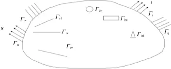
Fig.2 Notations for a body with multiple cracks and inclusions under imposed load and displacements
XFEM permits special functions to be incorporated in the finite element method by virtue of partition of unity. These enrichment functions can evolve with interface geometry,and thus have greater flexibility in modeling moving boundary problems without the burden of remeshing work. From Ref.[29],the displacement function for linear elastic extended finite element with a single crack or a single inclusion can be extended to thermoelastic multiple cracks and multiple inclusions.Thus,the displacement and temperature approximations for thermoelastic isolated multiple cracks or multiple inclusions can be written as Eqs.(9)and(10)

where M=n when the discontinuity is a crack surface, M=n t if the discontinuity and singularity is a crack tip, M=m if the discontinuity is inclusion,M=m+n t if crack and interface coexist in the same element;N are the finite element nodes,Ni,Nl,Nrrepresent the shape functions related to enriched nodes i,l,r;uiis the regular displacement freedom degree vector,tiis the regular temperature freedom degree vector;aljis the enriched displacement freedom degree vector for the j-th discontinuity or singularity (here,the discontinuity contains crack surfaces and inclusions),bljis the enriched temperature freedom degree vector for the j-th discontinuity or singularity;crkis the enriched displacement freedom degree vector for the k-th inclusion, drkis the enriched temperature freedom degree vector for the k-th inclusion;ψj(x)represents the j-th discontinuity or singularity enrichment function,ψk(x)represents the kth inclusion enrichment function.The formulation of ψj(x) orwill be detailed as below.

When an element contains a crack tip,the functions for enriched crack tip displacement field in the element free Galerkin(EFG)method are repeated[32,33].
The enrichment functions for single crack asymptotic near a tip displacement field are given in Ref.[20].Then,theenrichment functions for multiple cracks asymptotic near a tip displacement field can be extended as follows

For each inclusion enrichment,the following function[34] is adopted

where Γinkrepresents the k-th interface of inclusion,and proj x represents the mapping operator.
Specially,Moës et al.[34]addressed the enrichment problem of a single circular inclusion using an absolute value enrichment function.Therefore,each circular inclusion enrichment function can be written as

where ςikare the nodal level set values for the k-th inclusion interface level set function,and m is the number of inclusions.This enrichment shows optimal convergence.In addition,the enrichment function can directly get the nodal true displacement without extra post process work.
For temperature enrichment,if the discontinuity is an adiabatic crack,the temperature discontinuity enrichment function is Eq.(11),and the flow of heat is interrupted by a crack edge.As a result,the field shows a singularity near the crack tip,and the temperature derivative singularity or heat flux singularities should be ensured by modifying the temperature shape function,i.e.,the temperature enrichment function is the first branch function of Eq.(12).If the discontinuity is an inclusion,then the temperature enrichment function is Eq.(13).
Hence,with overall consideration of Eqs.(9)–(13),we can get the XFEM thermoelasticity approximation for 2-D domains with multiple defects(cracks or inclusions)as follows


where N are the finite element node sets,Ncrare the sets of nodes with support crossed by crack faces,Ntipare the node sets in crack tip elements,Nincare the node sets in elements crossed by inclusion interfaces;n,nt and m are the numbers of cracks,crack tips,and inclusions,respectively;is defined as Eq.(13),is defined as Eq.(12)(mechanical problem)orin Eq.(12)(thermal problem).
Furthermore,according to Eq.(15),the vector of nodal unknowns can be written as

where u1and u2denote the classical displacement degrees of freedom,u3denotes the classical temperature degree of freedom;a1and a2denote the displacement degrees of freedom for enriched crack faces,a3denotes the temperature degree of freedom for enriched crack faces;b1and b2denote the displacement degrees of freedom for enriched crack tips,b3denotes the temperature degree of freedom for enriched crack tips;c1and c2denote the displacement degrees of freedom for enriched inclusion interfaces,and c3denotes the temperature degree of freedom for enriched inclusion interfaces.
Hence,the discrete equations for thermoelastic problems [6,20,24]without considering thermal structure coupling can be written as

The stiffness matrix for thermal problems is

where subscript 3 denotes temperature freedom.

The force vector for the thermal parts of the problem can be written as

whereβ=2,ψβis the crack tip enrichment function defined as Eq.(12),ψ is the enrichment function for inclusion interfaces defined as Eq.(13),Niis the finite element shape function,Q is the thermal source,H is the Heaviside function,Γqis the boundary of thermal flux,andis the thermal flux on Γq.
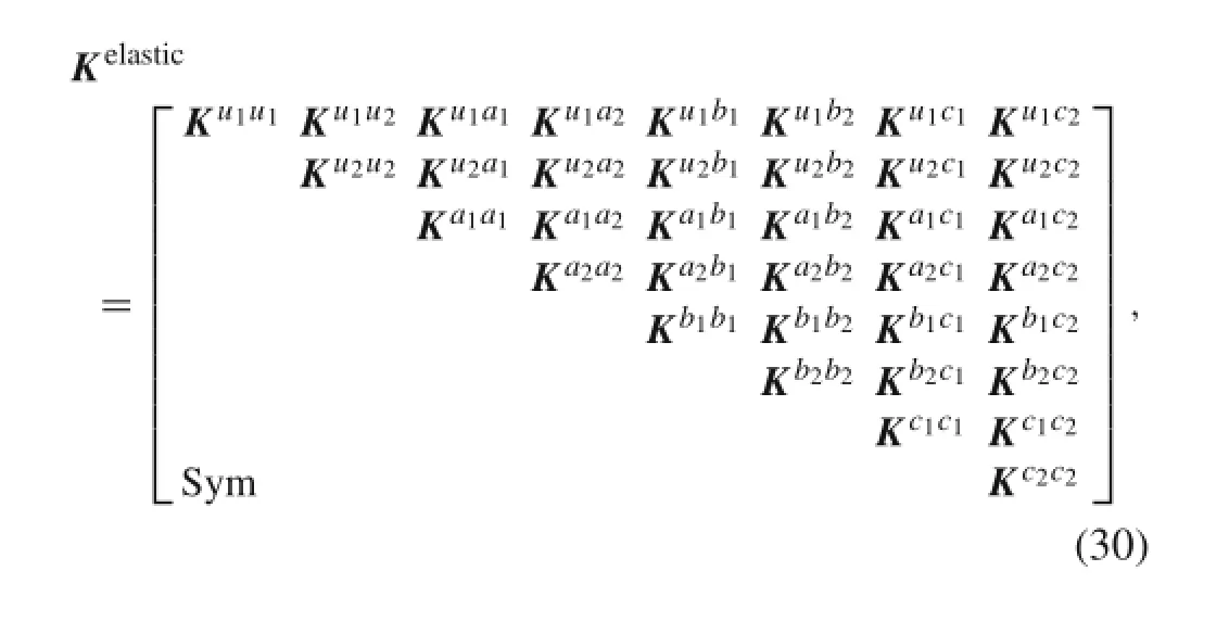
where
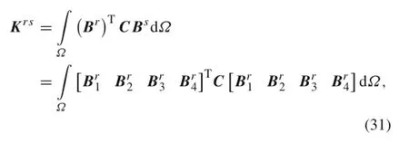
where C is the constituent tensor;r,s=u1,u2,a1,a2, b1,b2,c1,c2;Br,Bsare geometry matrices as follows
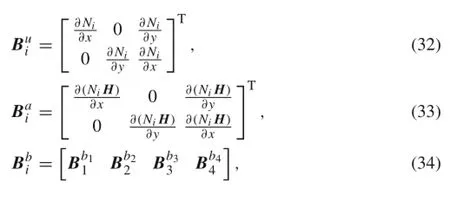
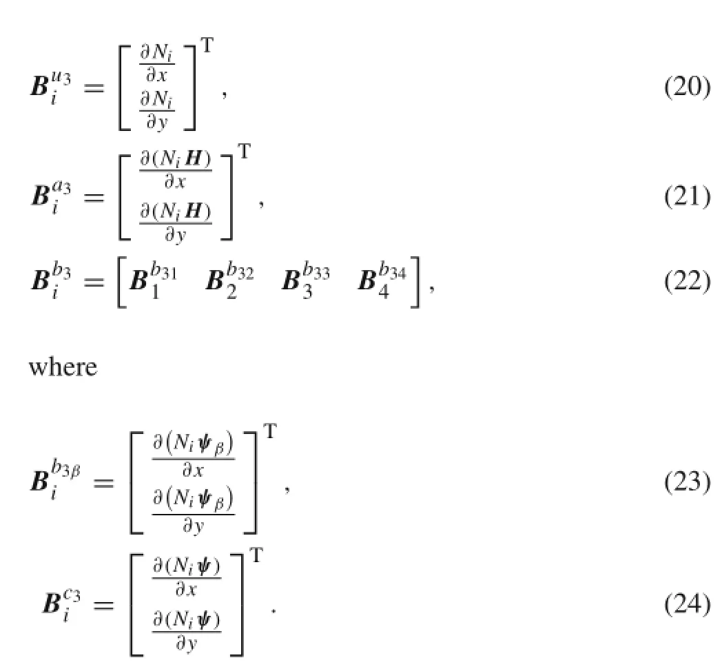
where
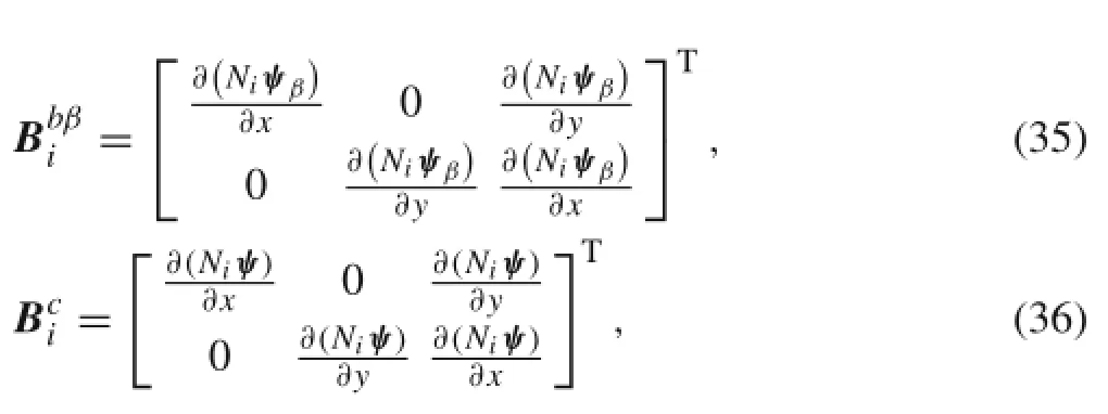
where i=1,2,3,4,β=1,2,3,4,ψβis the crack tip enrichment function defined as Eq.(12),and ψ is the enrichment function for inclusion interfaces defined as Eq.(13).
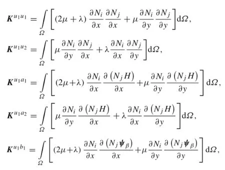
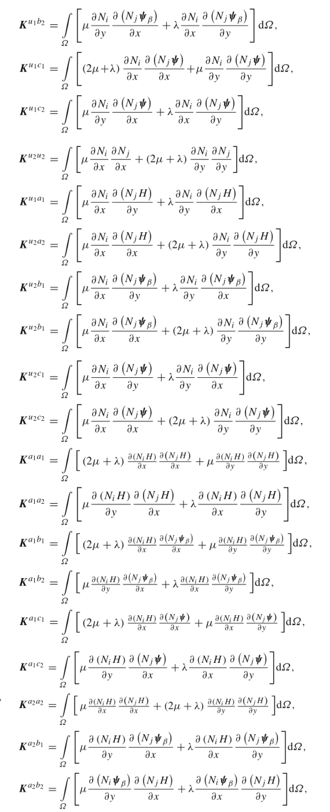
The formulation of stiffness matrix components for elastic problems can be detailed in“Appendix”.


Fig.3 Integration sub-domains around a crack
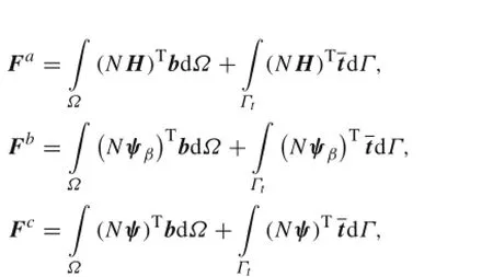
where i=1,2,3,4,β=1,2,3,4,ψβis the crack tip enrichment function defined as Eq.(12),and ψ is the enrichment function for inclusion interfaces defined as Eq.(13).
After the system matrices are constructed,the Newmark time integration method is adopted to get the structural response for the thermal and elastic parts.
Conventional Gauss quadrature is usually not adequate for the finite element integration at crack faces or around crack tips and inclusion interfaces.Here,the discontinuous or singular elements are divided into some sub-triangles[19]that have boundaries aligned with crack faces(inclusion interfaces)and element edges.After sub-domains are constructed for integration,the Gauss quadrature formula is implemented for each sub-triangle as shown in Fig.3(here,sub-domains resulting from the crack are simply plotted;for sub-domains from inclusion,a similar method is adopted).To be specific, a 3×3 Gauss quadrature is adopted for integration in unenriched elements,a 7×7 Gauss quadrature is for elements containing Heaviside enriched node(s)or inclusion interface enriched nodes,and a 9×9 Gauss quadrature is for elements containing crack tip enriched node(s).
4 Level set method
The level set method[35]was introduced by Osher and Sethian[36]to capture moving interfaces,and has been widely used in moving interface and free boundary problems.It is based on a continuous formulation using partial differential equations(PDEs)that represent the zero isocontour of a level set function.Using the level set method,we can implicitly capture it by solving a PDE for the level set function without explicitly tracking an evolving surface.Since the level set should be restricted to a narrow band near the zero level set,the moving surface can be represented by the zero isosurface of the level set function.Thus,the evolution equation for the level set function[36]can be written as

For example,signed distance function[17]can be adopted as function φ(x,t)

where the sign is positive(negative)if x is outside(inside) the contour defined by Γ(t).
In this paper,a special case of static interface is assumed, so the material interface can be represented using the level set method.For a circular inclusion[17],we have

where Ωcis the domain of circular inclusion;andare the center and radius of the i-th inclusion,respectively.
5 Interaction integral method(M-integral)for a single thermoelastic crack
Domain forms of the interaction integral[37,38]along with XFEM in thermoelastic crack problems are used to obtain the mixed-mode SIFs.Here,the thermoelastic M-integral is based on the conservative J integral as

whereΓ is the arbitrary contour that starts from a point on the lower crack face and ends at another point on the upper crack face;n1is the first component of the outward unit normal to Γ;Tiand uiare components of the traction and displacement vectors onΓ,respectively;and is the domain enclosed byΓ; ΔT is the change of temperature that may be a function of position;
The energy release rate G can be related to the SIFs by the following Irwin’s relation[39]

where

where E and ν are Young’s modulus and the Poisson ratio, respectively.
In this paper,an auxiliary state is used to extract the mixed-mode SIFs.Consider that two equilibrium states represented by 1 and 2 are superposed for the mixed-mode cracks[29], of which State 1 corresponds to the actual solution state and State 2 corresponds to an auxiliary pure elastic solution. Hence,in the auxiliary solution,the change of temperature ΔT(2)is 0.By substituting the two solutions into Eqs.(42) and(43),and noting the equivalence of the J-integral and the energy release rate G,these expressions are equated to yield

where the interaction strain energy density is given by

and

Using the divergence theorem,the first item in Eq.(45) can be converted into a classical area integral.Hence,the thermal M-integral[40]can be given as
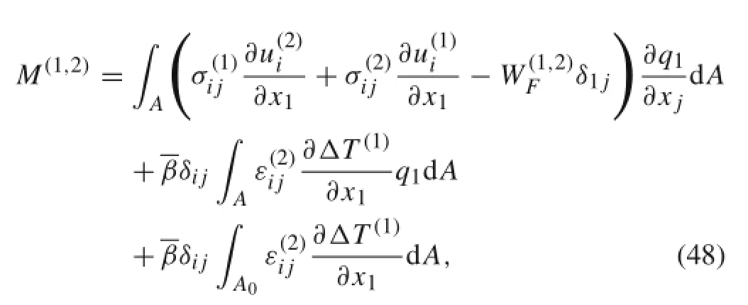
where A is illustrated in Fig.4(see Ref.[37]),A0is enclosed by C1,and the function q1varies continuously from unity on C1to zero on C2.
The mixed-mode SIFs can also be obtained using two auxiliary solutions.Represent the two solutions by Solution 2a and Solution 2b.LetThen,substitution of these values into Eq.(47) yields
Fig.4 Illustration of the area A for J-integral calculation(the J-integral path can enclose both crack tips)

By solving the above system of linear algebraic equations (49)and(50),the mixed-mode stress intensity factors can be obtained.
6 Numerical examples
6.1 Interaction between a single crack and a single circular inclusion under thermal/mechanical load
In this section,two numerical examples for the case of interaction between a single crack and a single circular inclusion (see Ref.[1])are presented to prove the accuracy of our method.The first and second examples involve the load types of uni-axial tension and uniform temperature field, respectively,and plane strain conditions are assumed in both examples.As depicted in Fig.1,the base material is the FGH95 powder metallurgy Nickel-based superalloy,and the inclusion is Al2O3.Young’s moduli of FGH95 and Al2O3are 205 and 67.2 GPa,respectively;Poisson ratios are 0.29 and 0.26,respectively;Dundur’s parameters[1,41,42]are α=0.91432 and β=0.20822,respectively.In order to simulate the plate’s infinity,the plate’s dimensions are 20 times greater than those of inclusions and cracks.
6.1.1 An infinite plate with a straight linear crack near a circular inclusion under uniaxial tension load
In this example,our proposed method is applied to a straight linear crack with an angle of θ=0 near a circular Al2O3inclusion under a remote unit uniaxial tension load.Here,the calculated SIFs are normalized by K0=K01=1.2533.
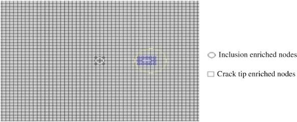
Fig.5 Finite element mesh with crack tip enriched nodes,and inclusion enriched nodes around the crack and the inclusion
In the FEM discretization,the square isoparametric element is adopted.Figure 5 presents the finite discretization with crack tip enriched nodes and inclusion enriched nodes (around crack and inclusion),as well as the J-integral domain.The J-integral domain around the crack tip are set in the range between the crack tip and the inclusion for the crack near an inclusion[43].
Figures 6 and 7 illustrate the normalized SIFs for various normalized crack lengths with different distances from crack tip to interface.For comparison,those results from the body force method by Chen are also provided in the figures.As can be seen,the solutions from our proposed method agree wellwith those from the body force method.From Figs.6 and 7,the difference between K(A)and K(B)decreases with increasing d/R.This may be attributed to the fact that the inclusion has little effect on SIFs at long distances.
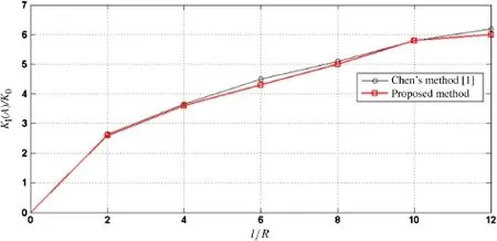
Fig.6 Normalized stress intensity factors KI(A)for Al2O3/FGH95 under uniaxial tension for different crack lengths l/R with the distance from crack tip A to interface d/R is 0.1

Fig.7 Normalized stress intensity factors KI(A)for Al2O3/FGH95 under uniaxial tension for different crack lengths l/R with the distance from crack tip A to interface d/R is 1
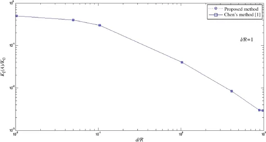
Fig.8 Normalized stress intensity factors for Al2O3/FGH95 under uniform temperature fields for different distances d/R from crack tip A to interface with l/R=1

Fig.9 Normalized stress intensity factors for Al2O3/FGH95 under uniform temperature fields for different distances d/R from the crack tip A to the interface with l/R=1
6.1.2 An infinite plate with a straight linear crack near a circular inclusion under uniform temperature load In this example,our proposed method is applied to a straight linear crack with an angle of θ=0 near a circular Al2O3inclusion under uniform temperature load.The thermal expansion coefficients of FGH95 and Al2O3areandrespectively.The value of l/R is 1,ΔT=10°C,and the normalized SIF is
Figures 8 and 9 present the normalized SIFs for different distances from crack tip to interface.Again,good coincidence for the solutions from our proposed method and the body force method can be found.From these figures, both K(A)and K(B)decrease with increasing d/R.When d/R>10,the thermal effect vanishes and the thermal stress has little effect on the SIFs,because Al2O3has a small elastic modulus but a similar thermal expansion to FGH95(only 25%smaller than that of FGH95).Figure 10 shows the resultant stress distributions of σxx,σxy,σyyand von Mises stress σVMwhen d/R=1.From Fig.10,it can be seen that the four stress plots are somewhat strange.This is probably due to that the meshes around the crack or the inclusion are not refined enough.
6.2 Interaction between a notch and multiple triangular microscopic inclusions under displacement controlling load

Fig.10 (Color online)Stress distributions under uniform temperature fields when d/R=1
In this case,we simulate a wedge splitting test[44,45],and replace the circular aggregates in Ref.[45]with triangular ones.The numerical sample geometry and boundary conditions are shown as Fig.11,in which all dimensions are in the unit of a meter.The sample contains a notched cube and 60 triangular aggregate inclusions embedded in cement paste.The maximum radius of an aggregate is 0.008 m,and the minimum is 200×10−6m.As depicted in Fig.12,the sample is modeled by a 2-D slice.The heterogeneous microstructure is represented in the area below the notch where the crack is expected to propagate.Here,the loading velocity of 1×10⁻³mm/day is adopted.Since the aggregate is an elastic material with a Young’s modulus of 58 GPa and a Poisson ratio of 0.3,the aggregates are assumed to be not damaged. In contrast,the cement paste is a viscoelastic material with the same material properties as those in Ref.[45],so that it may be damaged during loading.

Fig.11 Geometry and boundary conditions for the wedge splitting test

Fig.12 One notch and multiple inclusions
The displacement uimpis imposed on the neck of the sample at a constant rate,and the notch propagates at the tip of the notch until the sample fractures.Since the boundary conditions are displacement constraints,crack growth is stable and the crack cannot grow further if uimpremains constant. The concrete microstructure is in the area below the notch where the crack may propagate,but cannot propagate in the aggregates.
The tensile stress fracture criterion is adopted here,i.e., C=σ−σcr,where C denotes the fracture criterion(when C>0,the sample initiates damage),σ is the stress,andσcris the tensile strength(σcr=1.5 MPa here).Figure 13 presents the stiffness versus time curve,where stiffness is computed as the average stress divided by average strain.Figure 14 gives the average damage versus time curve,where the average damage is the damaged volume fraction of the sample;it reflects the changes of mean stiffness value in sample.From Figs.13 and 14,it can be found that the stiffness decreases with the increase of average damage.When the time is 450 days,the stiffness approaches to 0,indicating the occurrence of material fracture.
6.3 Interaction between multiple microscopic inclusions under mechanical load or thermal expansion
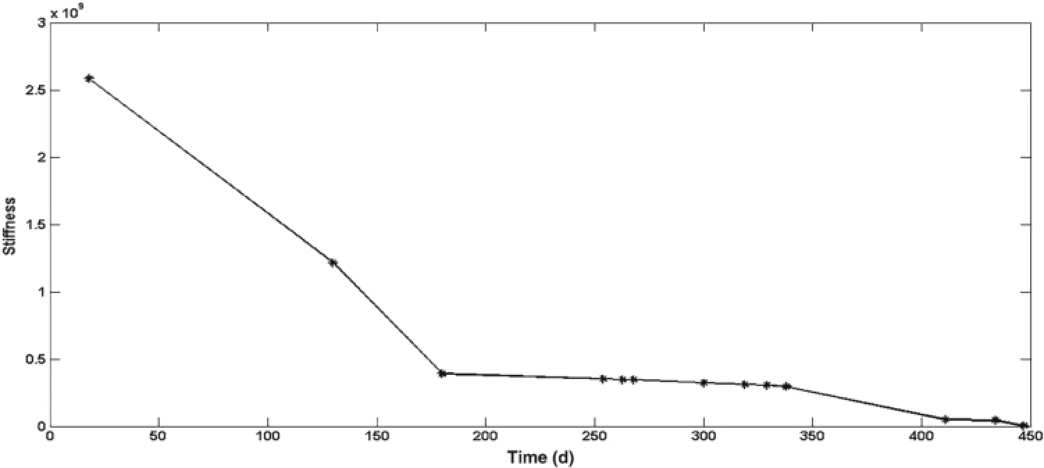
Fig.13 Average stiffness versus time
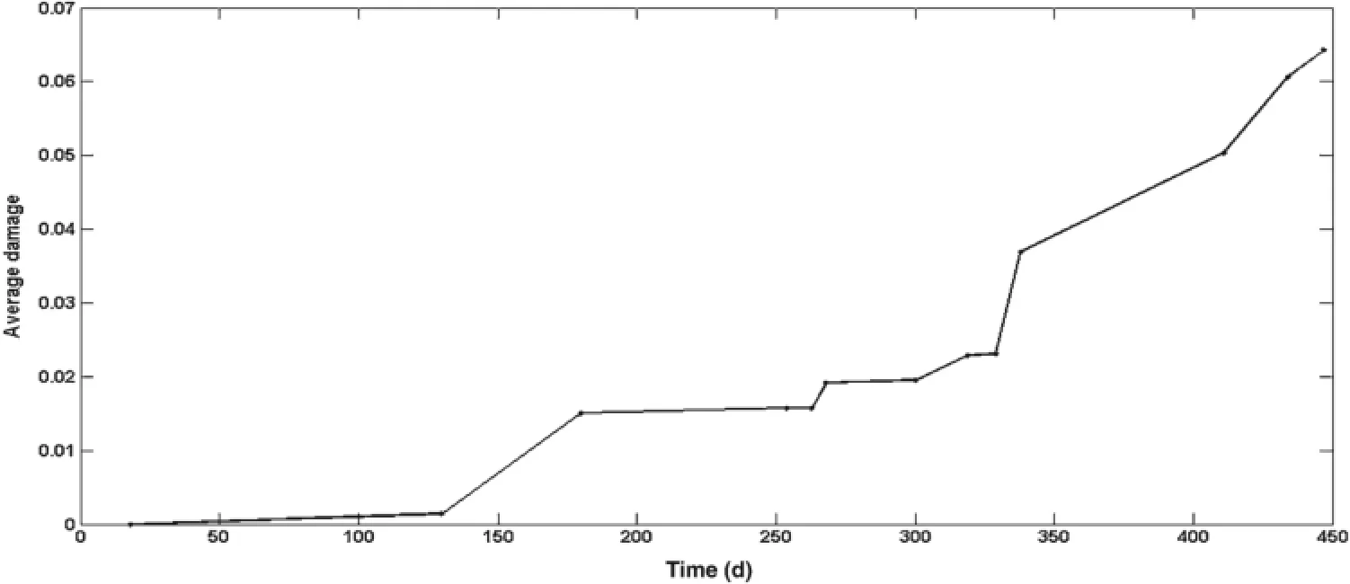
Fig.14 Average damage versus time
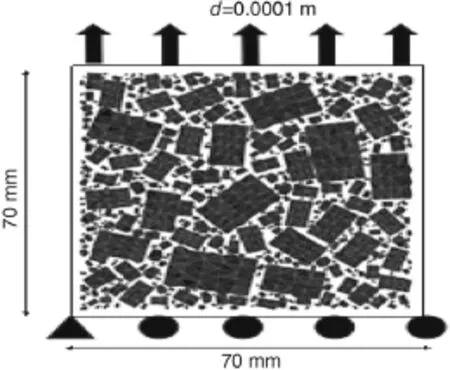
Fig.15 Concrete specimen under thermomechanical load
In this section,we simulate a concrete specimen containing 500 aggregates with their grain size distribution following the Bolome reference curve[46].The specimen is a square with a side length of70 mm,and the maximum radius of the aggregate is 0.008 m,as shown in Fig.15.Here,the problem is at meso-scale and limited to two dimensions.In fact,concrete consists of many different shapes of aggregates or cracks embedded in paste.In this study,we only consider circular, triangular,and rectangular shapes of aggregates(inclusions), which are randomly distributed in the paste and do not intersect each other.The paste(matrix)is a viscoelastic material with a Young’s modulus of 12 GPa and a Poisson ratio of 0.3,while the aggregate(inclusions)is an elastic material with a Young’s modulus of 59 GPa and a Poisson ratio of 0.3.Assume the concrete thermal expansion coefficient is 10×10−6°C−1.The boundary conditions of the thermoelastic problem are as follows:a displacement of d=0.0001 m is applied to the top of the specimen and the temperature of the specimen decreases by 15°C at the same time;the lower edge is fixed in the vertical direction and the lower left corner is fixed both in horizontal and vertical directions.
The aggregates are packed such that the total area of different shapes of aggregates in specimen is basically the same. All aggregate surfaces in the concrete are enriched by the enrichment function of Eq.(13).When multiple aggregate inclusions exist in an element,refinement on the elements around multiple aggregate inclusions must be carried out.
Figures 16 and 17 show the simulation results of a von Mises stress(unit:Pa)distribution in the specimen with different shapes of aggregates under pure mechanical load and thermomechanical load,respectively.It can be seen that the specimen with triangular inclusions has the maximum von Mises stress,while von Mises stress in the specimen with circular inclusions is the minimum.That is to say,concretewith triangular inclusions has more brittle mechanical behavior than that with circular ones.These results agree with those of the uni-axial creep test in Ref.[44].
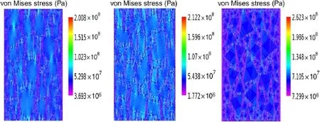
Fig.16 (Color online)von Mises stress distribution in the specimen with different shapes of aggregates under pure mechanical load:left(circular shape),middle(rectangular shape),and right(triangular shape)

Fig.17 (Color online)von Mises stress distribution in the specimen with different shapes of aggregates under thermomechanical load:left(circular shape),middle(rectangular shape),and right(triangular shape)
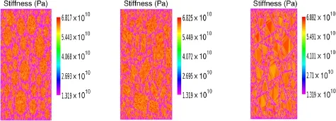
Fig.18 (Color online)Stiffness distribution in the specimen with different shapes of aggregates and average strain of the specimen in x-and y-directions under thermomechanical load:left(circular shape),middle(rectangular shape),and right(triangular shape)
Figure 18 gives the stiffness distribution of the three different concretes under thermomechanical load.As can be seen, the stiffness distribution in the specimen with different shapes of aggregates is almost identical,but the specimen with triangular aggregates is much stiffer than the others.This may be due to the angularity and interaction between aggregates. These results also agree with those of the uni-axial creep test in Ref.[44].
Table 1 shows the average strain and average stress of the specimen in x-and y-directions.As can be seen,all strains in the y-direction are identical and the stresses in the y-directionare basically equal due to the equal displacement boundary in the y-direction;on the other hand,there are some differences for the strains and stresses in the x-direction due to aggregates’different shapes and angularities,different distances between aggregates,and their different interactions, but these differences are not significant on the whole.

Table 1 Average strain and average stress(unit:Pa)of the specimen in x-and y-directions
7 Conclusions
In summary,an extended finite element method is proposed for analyzing thermoelastic problems of multiple inclusions or cracks.Firstly,the interaction between a single crack and a single inclusion under temperature or mechanical load is studied using XFEM.Then,the mechanical behavior of multiple defects is analyzed under temperature or mechanical load by investigating the effects of inclusion shape and angularity on a material’s thermomechanical response.In addition,discretized extended finite element approximations for displacement or the temperature field of multiple defects are given for solving thermoelastic problems.According to the simulation results from the Al2O3/FGH95 system under thermal and mechanical loads,thermal stress has little effect on the SIFs,especially when the distance between crack and inclusion is long.In our future work,we will take full advantage of the strength of XFEM to investigate the interaction between multiple cracks and various types of inclusions under dynamic thermomechanical load.
Acknowledgments The project was supported by the National Natural Science Foundation of China(Grants11471262,50976003,51136005).
Appendix
The formulation of stiffness matrix components for the elastic problem is:

where C is the constituent tensor,and(r,s=u1,u2,a1,a2, b1,b2,c1,c2).

References
1.Chen,Y.:Influence of inclusion on the stress intensity factors under thermal/mechanical loads in a PM superalloy.Appl.Math.Model. 33,386–397(2009)
2.Wang,X.,Chen,W.Q.:Three-phase elliptical inclusions with an internal stress field of linear form.Math.Mech.Solids19,735–743 (2014)
3.Hwu,C.,Liao,C.Y.:A special boundary element for the problems of multi-holes,cracks and inclusions.Comput.Struct.51,23–31 (1994)
4.Fan,M.,Yi,D.K.,Xiao,Z.M.:A Zener–Stroh crack interacting with a coated inclusion with generalized Irwin plastic zone correction.Int.J.Solids Struct.51,3399–3409(2014)
5.Larsson,S.G.,Harkegard,G.:On the finite element analysis of crack and inclusion problems in elastic–plastic materials.Comput. Struct.4,293–305(1974)
6.Jiang,S.,Du,C.,Gu,C.,et al.:XFEM analysis of the effects of voids,inclusions and other cracks on the dynamic stress intensity factor of a major crack.Fatigue Fract.Eng.Mater.Struct.37,866–882(2014)
7.Yu,H.J.,Wu,L.Z.,Guo,L.C.,et al.:Investigation of mixed-mode stress intensity factors for nonhomogeneous materials using interaction integral method.Int.J.Solids Struct.46,3710–3724(2009)
8.Chopp,D.L.,Sukumar,N.:Fatigue crack propagation of multiple coplanar cracks with the coupled extended finite element/fast marching method.Int.J.Eng.Sci.41,845–869(2003)
9.Daux,C.,Moës,N.,Dolbow,J.,et al.:Arbitrary branched and intersecting cracks with the extended finite element method.Int.J. Numer.Methods Eng.48,1741–1760(2000)
10.Budyn,E.Z.,Moës,N.,Belytschko,T.:A method for multiple crack growth in brittle materials without remeshing.Int.J.Numer. Methods Eng.61,1741–1770(2004)
11.Loehnert,S.,Belytschko,T.:Crack shielding and amplification due to multiple microcracks interacting with a macrocrack.Int.J.Fract. 145,1–8(2007)
12.Danas,S.:Global energy minimization for multiple fracture growth.http://hdl.handle.net/10993/15109
13.Natarajan,S.,Chakraborty,S.,Ganapathi,M.,et al.:A parametric study on the buckling of functionally graded material plates with internal discontinuities using the partition of unity method.Eur.J. Mech.A Solids 44,136–147(2014)
14.Sundararajan,N.,Stéphane,B.,Mahapatra,D.R.:Numerical integration over arbitrary polygonal domains based on Schwarz–Christoffel conformal mapping.Int.J.Numer.Methods Eng.80, 103–134(2009)
15.Cahill,L.M.A.,Natarajan,S.,Bordas,S.P.A.,etal.:An experimental/numerical investigation into the main driving force for crack propagation in uni-directional fibre-reinforced composite laminae. Compos.Struct.107,119–130(2014)
16.Stéphane,B.,Nguyen,P.V.,Dunant,C.,et al.:An extended finite element library.Int.J.Numer.Methods Eng.71,703–732(2007)
17.Sukumar,N.,Chopp,D.,Moës,N.,etal.:Modeling holesand inclusions by level sets in the extended finite-element method.Comput. Method.Appl.Mech.Eng.190,6183–6200(2001)
18.Khoei,A.R.,Moallemi,S.,Haghighat,E.:Thermo-hydro-mechanical modeling of impermeable discontinuity in saturated porous media with X-FEM technique.Eng.Fract.Mech.96,701–723(2012)
19.Matthew,J.P.:Variable Amplitude Fatigue Analysis Using Surrogate Models and Exact XFEM Reanalysis.[Ph.D.Thesis], University of Florida,Florida,USA(2003)
20.Bayesteh,H.,Afshar,A.,Mohammadi,S.:Thermo-mechanical fracture study of inhomogeneous cracked solids by the extended isogeometric analysis method.Eur.J.Mech.A Solids 51,123–139 (2015)
21.Sukumar,N.,Huang,Z.,Prévost,J.,et al.:Partition of unity enrichment for bimaterial interface cracks.Int.J.Numer.Methods Eng. 59,1075–1102(2004)
22.Duflot,M.:The extended finite element method in thermoelastic fracture mechanics.Int.J.Numer.Methods Eng.74,827–847 (2008)
23.Yu,H.J.,Kitamura,T.:Anew domain-independent interaction integral for solving the stress intensity factors of the materials with complex thermo-mechanical interfaces.Eur.J.Mech.A Solids 49, 500–509(2015)
24.Zamani,A.,Eslami,M.R.:Implementation of the extended finite element method for dynamic thermoelastic fracture initiation.Int. J.Solids Struct.47,1392–1404(2010)
25.Pant,M.,Singh,I.V.,Mishra,B.K.:A numerical study of crack interactions under thermo-mechanical load using EFGM.J.Mech. Sci.Technol.25,403–413(2011)
26.Hosseini,S.S.,Bayesteh,H.,Mohammadi,S.:Thermo-mechanical XFEM crack propagation analysis of functionally graded materials. Mat.Sci.Eng.561,285–302(2013)
27.Pathak,H.,Singh,A.,Singh,I.V.:Fatigue crack growth simulations of bi-material interfacial cracks under thermo-elastic loading by extended finite element method.Eur.J.Comput.Mech.22,79–104(2013)
28.Stolarska,M.,Chopp,D.,Moës,N.,et al.:Modelling crack growth by level sets in the extended finite element method.Int.J.Numer. Methods Eng.51,943–960(2001)
29.Yau,J.F.,Wang,S.S.,Corten,H.T.:Mixed-mode crack analysis of isotropic solids using conservation laws of elasticity.J.Appl. Mech.47,335–341(1980)
30.Guo,L.C.,Guo,F.N.,Yu,H.J.,et al.:An interaction energy integral method for nonhomogeneous materials with interfaces under thermal loading.Int.J.Solids Struct.49,355–365(2012)
31.Rajesh,P.,Subir,D.,Santwana,M.:A two-dimensional problem of a mode I crack in a type III thermoelastic medium.Math.Mech. Solids 18,506–523(2013)
32.Fleming,M.,Chu,Y.A.,Moran,B.,et al.:Enriched element free Galerkin methods for crack tip fields.Int.J.Numer.Methods Eng. 40,1483–1504(1997)
33.Belytschko,T.,Black,T.:Elastic crack growth in finite elements with minimal remeshing.Int.J.Numer.Methods Eng.45,601–620 (1999)
34.Moës,N.,Cloirec,M.,Cartraud,P.,et al.:A computational approach to handle complex microstructure geometries.Comput. Method.Appl.Mech.Eng.192,3163–3177(2003)
35.Osher,S.,Fedkiw,R.P.:Level set methods:an overview and some recent results.J.Comput.Phys.169,463–502(2001)
36.Osher,S.,Sethian,J.:Fronts propagating with curvature dependent speed:algorithms based on Hamilton-Jacobi Formulations.J. Comput.Phys.79,12–49(1988)
37.Leslie,B.S.,Orly,D.:The conservative M-integral for thermoelastic problems.Int.J.Fract.125,149–170(2004)
38.Fung,Y.C.:Foundation of Solid Mechanics.Prentice Hall,New Jersey(1965)
39.Irwin,G.R.:Analysis of stress and strains near the end of a crack traversing a plate.J.Appl.Mech.24,361–364(1957)
40.Li,F.Z.,Shih,C.F.,Needleman,A.:A comparison of methods for calculating energy release rates.Eng.Fract.Mech.21,405–421 (1985)
41.Dundurs,J.:Effect of elastic constants on stress in a composite under plane deformation.J.Compos.Mater.1,310–322(1967)
42.Muller,W.H.,Schmauder,S.:Stress-intensity factors of r-cracks in fiber-reinforced composites under thermal and mechanical loading. Int.J.Fract.59,307–343(1993)
43.Yang,L.H.,Chen,Q.,Li,Z.H.:Crack-inclusion interaction for mode II crack analyzed by Eshelby equivalent inclusion method. Eng.Fract.Mech.71,1421–1433(2004)
44.Giorla,A.:Modelling of Alkali-Silica Reaction under Multi-Axial Load.[Ph.D.Thesis],Ecole Polytechnique Fédérale de Lausanne, Lausanne,Swiss(2013)
45.Cécot,C.:Etude micromécanique par simulation numérique en éléments finis des couplages viscoélasticité-croissance des fissures dans les composites granulaires de type béton.[Ph.D.Thesis], Ecole Polytechnique Fédérale de Lausanne,Lausanne,Swiss (2001)(in French)
46.Dunant,C.:Experimental and modelling study of the alkali-silica-reaction in concrete.[Ph.D.Thesis],Ecole Polytechnique Fédérale de Lausanne,Lausanne,Swiss(2009)
✉ Yufeng Nie yfnie@nwpu.edu.cn
1School of Mathematics and Statistics,Xuchang University, Xuchang 461000,China
2School of Science,Northwestern Polytechnical University, Xi’an 710072,China
26 August 2015/Revised:18 May 2016/Accepted:12 June 2016/Published online:30 September 2016
- Acta Mechanica Sinica的其它文章
- Closed-form solutions for free vibration of rectangular FGM thin plates resting on elastic foundation
- MoM-based topology optimization method for planar metallic antenna design
- Dilation and breakage dissipation of granular soils subjected to monotonic loading
- A semi-analytical approach for calculating the equilibrium structure and radial breathing mode frequency of single-walled carbon nanotubes
- Time-delay identification for vibration systems with multiple feedback
- Plaque components affect wall stress in stented human carotid artery:A numerical study

