Static and dynamic responses of a microcantilever with a T-shaped tip mass to an electrostatic actuation
B.Firouzi·M.Zamanian·S.A.A.Hosseini
Static and dynamic responses of a microcantilever with a T-shaped tip mass to an electrostatic actuation
B.Firouzi1·M.Zamanian1·S.A.A.Hosseini1
©The Chinese Society of Theoretical and Applied Mechanics;Institute of Mechanics,Chinese Academy of Sciences and Springer-Verlag Berlin Heidelberg 2016
In this study,nonlinear static and dynamic responses of a microcantilever with a T-shaped tip mass excited by electrostatic actuations are investigated.The electrostatic force is generated by applying an electric voltage between the horizontal part of T-shaped tip mass and an opposite electrode plate.The cantilever microbeam is modeled as an Euler–Bernoulli beam.The T-shaped tip mass is assumed to be a rigid body and the nonlinear effect of electrostatic force is considered.An equation of motion and its associated boundary conditions are derived by the aid of combining the Hamilton principle and Newton’s method. An exact solution is obtained for static deflection and mode shape of vibration around the static position.The differential equation of nonlinear vibration around the static position is discretized using the Galerkin method.The system mode shapes are used as its related comparison functions.The discretized equations are solved by the perturbation theory in the neighborhood of primary and subharmonic resonances. In addition,effects of mass inertia,mass moment of inertia as well as rotation of the T-shaped mass,which were ignored in previous works,are considered in the analysis.It is shown that by increasing the length of the horizontal part of the T-shaped mass,the amount of static deflection increases, natural frequency decreases and nonlinear shift of the resonance frequency increases.It is concluded that attaching an electrode plate with a T-shaped configuration to the end of the cantilever microbeam results in a configuration with larger pull-in voltage and smaller nonlinear shift of the reso-nance frequency compared to the configuration in which the electrode plate is directly attached to it.
MEMS·Electrostatic·Static deflection· Natural frequency·Pull-in voltage·Perturbation theory· T-shaped mass·Primary and subharmonic resonances
DOI 10.1007/s10409-016-0596-9
1 Introduction
Electrostatic sensors are among the most successful applications of micro-systems.Examples of these sensors include pressure sensors,accelerometers,gyroscopes,and mass chemical sensors.A microbeam with an electrode on the opposite side is the basis for many of these sensors.These sensors are classified into two types:resonant sensors and non-resonant sensors.In non-resonant sensors,a direct-current(DC)voltage is applied between the microbeam and the opposite electrode.The electrostatic force due to the DC voltage deflects the microbeam to a new equilibrium position,which is called static deflection.When the quantity under measurement varies,the static position of the system also changes and,as a result,the capacitance of the microbeam and the opposite electrode varies.The quantity of interest is then calculated using the change in the capacitance.Resonant sensors are highly sensitive sensors,where a combination of alternating-current(AC)and DC voltages are applied between the microbeam and the opposite electrode. In these systems,the microbeam is oscillated around a static position,and the quantity under measurement is measured by monitoring the shift of the resonant frequency at the primary excitation[1].
One of the factors that causes damage to these systems is the pull-in instability that happens when the elasticity restor-ing force of the microbeam is unable to resist against the electrostatic force and therefore comes in contact with the opposite electrode.The voltage at which this phenomenon occurs is called the pull-in voltage[2].
Performance of these systems depends on the change in the static deflection induced by the DC voltage,the pull-in voltage and the dynamic response;therefore many studies have focused on these parameters.In a study,Xu and Jia[3]investigated the dynamic and static responses of a micro-cantilever under electrostatic excitation.They examined the forced response in the system under resonant and non-resonant conditions using perturbation theory.They also determined the parameters of the microbeam in an attempt to eliminate unfavorable dynamic properties such as jump phenomena.Chartejee and Pohit[4]used a reduced order method with 5 modes to conduct static and dynamic analysis on a micro-cantilever.They showed that in systems with relatively high distance to the electrode,including the effects of nonlinear curvature and nonlinear inertia predicts more accurate results.Rasekh and Khadem[5]considered the effects of nonlinear curvature and nonlinear inertia in a study of the pull-in voltage in a nano-tube under electrostatic excitation using the Galerkin method.They discretized the partial differential equations and the resulting equations were solved by the direct numerical integration method.A one-mode analysis method on the pull-in instability of micro-structures under electrostatic loading was presented by Zhang and Zhao[6]. They showed that the first mode is the dominant deflection shape for the beam/plate structure under electrical actuation and small axial load.
Fang and Li[7]studied the dynamic pull-in of a micro-cantilever and a clamped–clamped microbeam by including the effects of a fringing field and compared the results with experimental results.Huang et al.[8]Chen proposed a modified deformation function to calculate the pull-in voltage in a cantilever microbeam with residual stress by considering the effects of angle and curvature.In order to validate the analytical model,three experimental models with different lengths were fabricated and the results of the analysis were compared with the experimental results.
Rahaeifard and Ahmadian[9]considered the straingradient theory to derive the equations of motion and obtained a numerical solution for the equation.They showed that static deflection and pull-in voltage depend on the size. Other works studied the effects of size using the modified couple stress theory[10,11].In Refs.[12,13],the effects of Van der Waals force and Casimir force on the static deflection of a microbeam were examined.Numerous works have been conducted on the geometry in order to optimize the mechanical response of MEMS.Boudjet et al.[14]studied the micro-cantilever with different shapes and sizes and stated that the only way to improve the sensitivity in a silicon micro-cantilever density sensor is through optimizing the geometry.Abdalla et al.[15]studied the optimum shape for a capacitive microbeam to maximize the pull-in voltage. They discretized the equations of motion by the finite element method(FEM)method and obtained optimum width and thickness for different boundary conditions.Design optimization and fabrication of a cantilever microbeam for a switch application was examined in Ref.[16].This work was an effort to optimize the length and thickness of the microbeam and its distance from the opposite electrode plate.The cantilever design was optimized using the Taguchi Method of design for the experiment[16].
In several works the applied voltage between the microbeam and the electrode plate was considered as a combination of AC–DC,and the nonlinear behaviors of the system at primary and secondary resonance cases were investigated[17–23].It has been shown that depending on the value of the nonlinear electrostatic actuation,nonlinear stretching term,nonlinear curvature and nonlinear inertia term,a softening or hardening behavior can be observed. Primary and secondary resonances of a clamped–clamped micro beam under symmetric electrostatic actuation on both sides have been investigated by Younesian et al.[24]. Ghayesh et al.[25]investigated the effect of size dependency on the secondary resonances of clamped–clamped microbeams.Primary and secondary resonances of a double-walled clamped–clamped carbon nano-tube(DWNT)were studied by Hajnayeb and Khadem[26].
All of the above mentioned studies analyzed or optimized the pull-in voltage,natural frequency and static and dynamic response of a single-layer or separate microbeam.Many other works have studied the effects of adding a tip mass or adding a second layer on a micro-cantilever.
In several works the effect of electrostatic actuation on the nonlinear vibration of a piezoelectrically actuated microresonator was examined.The dynamic equations were derived by the Hamilton principle and solved by the multiple scales method in the neighborhood of the primary and secondary resonances[27–29].A piezoelectric bimorph beam with a mass connected to one end of the micro-cantilever was studied by Wang and Meng[30].
In some works,resonant sensors were studied as micro-cantilevers with a tip mass[31–33].In Refs.[34–37], effects of location and size of the tip mass on the sensitivity and resonant frequency of an atomic force microscopy (AFM)micro-cantilever or a carbon nanotube(CNT)micro-cantilever were analyzed.These works showed that the tip mass reduced the resonant frequency,although a change in its location can have an adverse effect on the resonant frequency. They also showed that for low stiffness materials,sensitivity of an AFM micro-cantilever with a smaller tip mass is higher than one having a greater tip mass.For high stiffness materials,the difference in the sensitivity was negligible and for a greater tip mass,the sensitivity was only slightly higher.Inseveral works,a micro-nano gyroscope with a tip mass was analyzed[38,39].These works examined the effects of frequency change on spin rate and static and dynamic behaviors and also the effects of Van der Waals and Casimir forces on the static deflection and the pull-in voltage.
Alsaleem et al.[40]investigated nonlinear resonance and dynamic pull-in in resonators under electrostatic excitation and analyzed nonlinear phenomenon using experimental and theoretical methods.They introduced a sensor composed of a proof mass connected at two ends of a micro-cantilever. Nayfeh et al.[41]proposed a model for a sensor composed of a rigid plate connected to one end of a micro-cantilever with an applied AC–DC electrostatic force between the plate and the opposite electrode.They examined the pull-in voltage and conducted static and dynamic analyses.In order to derive the equations of motion,the Hamilton method was utilized and the Galerkin method was used to discretize the domain.Ouakad[42]studied the effect of nonlinearities on the response of a similar model under mechanical shock and electrostatic loading.
Zamanian and Karimiyan[43,44]investigated the static deflection and the primary resonance of a T-shaped mass connected to the midpoint of a clamped–clamped microbeam. In this configuration the electrostatic force was generated by applying an electric voltage between the horizontal part of a T-shaped mass and the opposite electrode plate.Here we investigate the static and dynamic behavior of a similar configuration.In contrast to previous work[43,44],where the T-shaped mass was connected to a clamped–clamped microbeam,here we assume that it is connected to the end of micro-cantilever.Although,Tadayon et al.[45,46]focused on this model in some of their works,they ignored the effects of mass inertia,mass moment of inertia,rotation of the T-shaped tip mass and also geometrical effects of the T-shaped tip mass.Moreover,they studied only the primary resonance response.So,no comprehensive study has ever conducted on a micro-cantilever with a T-shaped tip mass.In this article, these effects are taken into account.The equations of motion and the associated boundary conditions are found by a combination of the Hamilton principle and Newton’s method. Then,an exact solution is obtained for the static deflection and the mode shapes of vibration around the static position. The differential equation of nonlinear vibration around the static position is discretized using the Galerkin method.The system mode shapes are used as the related comparison functions.The discretized equations are solved by perturbation theory in the neighborhood of the primary and subharmonic resonances.In a particular case,size and geometry of the model would be the same as the model proposed by Nayfeh et al.[41],i.e.,a micro-cantilever with a rigid plate connected to its end.Therefore,in order to validate the model and the calculations,the results are compared with the results reported in Ref.[41].Finally,effects of geometrical sizes of T-shaped mass on the pull-in voltage,static deflection,natural frequency and nonlinear shift of resonance frequency are examined.As mentioned,for a case of specific geometrical dimension,the model we consider will be the same as that considered in Ref.[41].This means that this paper is also an effort to solve,for the first time,the equation of motion in Ref.[41]at subharmonic resonance.We note that jump phenomena encountered in pitchfork bifurcations at the subharmonic excitation have been introduced as criteria for a mass sensor,and so the results of this paper may be used in future for better design of these devices[47].
2 Modeling and formulation
The model presented in Fig.1a consists of a micro-cantilever in which the free end is connected to the T-shaped body. Both parts are made of silicon.The T-shaped tip consists of two parts,a horizontal plane parallel to the microbeam and a vertical part that connects the horizontal plane to the microbeam end.It is assumed that the T part shows a rigid behavior,and the cantilever beam is modeled as an Euler Bernoulli beam.
This assumption is justifiable because the boundary conditions of the horizontal plate are free and its thickness is several times of that of the cantilever beam.DC voltage is applied between the T-shaped horizontal plane and a fixed electrode plate.
The free body diagram of the considered microbeam is shown in Fig.1b,c.Using a Dirac delta function,the shear force Fsand moment,M,at the right boundary of microbeam may be included in the equation of motion.In this condition, the equation of motion and homogeneous boundary conditions will be as follows(see Appendix 1)
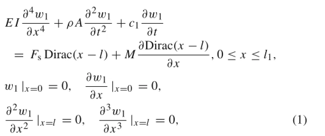
where t is time,x is the axial coordinate,w1is the transverse deflection of the microbeam,I is the area moment of inertia of the microbeam cross section,ρ is the material density,E is the modulus of elasticity,A is the cross-section area,and c1is the coefficient of equivalent viscous damping along the length of the microbeam.It should be noticed that the dominant component of the damping factor is thermoelastic damping[48,49].The electrostatic force per unit area between the electrode plates of a capacitor that are at distance d from each other is[50],where ε is thedielectric constant,Vp(Vac)is DC(AC)electrostatic voltage, and d is the initial distance between two electrode plates.

Fig.1 a System model.b Deflected microbeam.c Free body diagram of the T-shaped mass after cutting
So Feland Melmay be found by integration from force per unit area along the length of the horizontal part of the T-shaped body,as
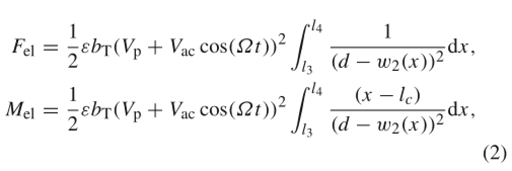
where b is the width of the microbeam,bTis the width of the horizontal part of the T-shaped tip mass,and Ω is the frequency of the AC voltage.w2(x)denotes the displacement of the T-shaped part,which may be described as below using Fig.2:


Moreover lc=(l1+l2)/2,where l2and l1are the distance between the right and left ends of the vertical part of the T-shaped mass from the clamped side of the microbeam.θ and wTare,respectively,the angular rotation and the mass center displacement of the T-shaped body,which are introduced as

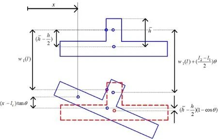
Fig.2 Schematic diagram of T-shaped body displacement

Now,by applying the Newton’s second law to the T-shaped mass,the equivalent shear force and moment at the common cross section of microbeam and T-shaped mass will be:

where l3(l4)is the distances between left(right)ends of the horizontal part of the T-shaped mass from the clamped side of the microbeam.Moreover,c2is the coefficient of the equivalent viscous damping along the length of the T-shaped mass. Note that the dominant component of the damping factor is squeeze film damping[51].mTand ITare,respectively, the mass and mass moment of inertia of the T-shaped body, which we introduce as
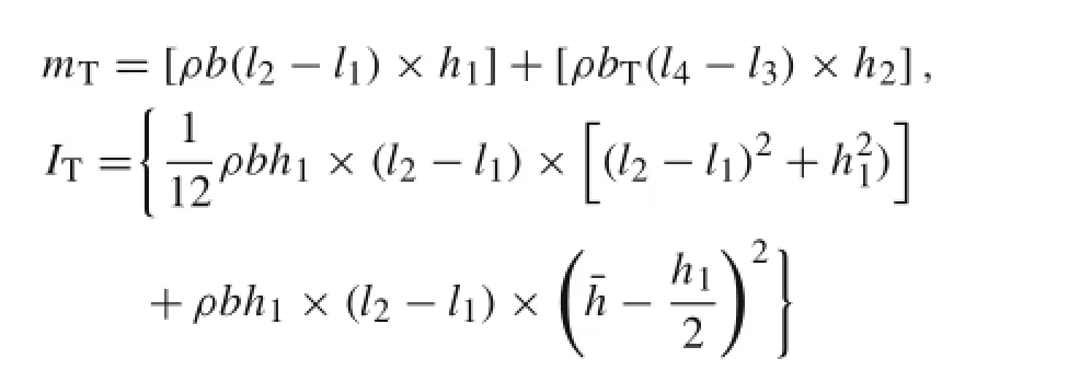

where h2is the thickness of the horizontal part of the T-shaped body and h1is the height of the vertical part of the T-shaped body.It must be noted that in Eq.(6)the moment of shear force is negligable in comparison with the other terms.
By combining Eqs.(1)and(6),the governing equation of motion and associated boundary conditions can be expressed as

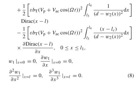
For convenience,we introduce the following set of non-dimensional parameters:

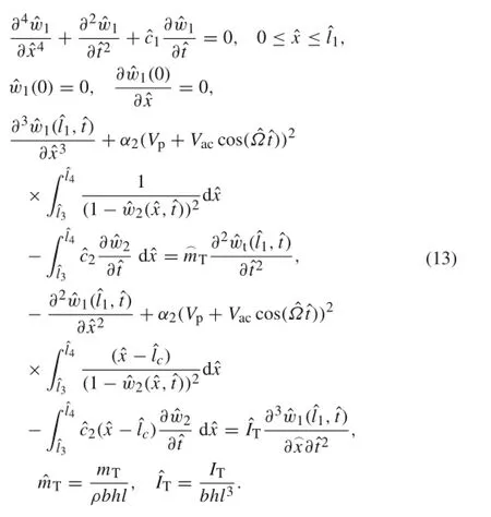
Using the non-dimensional parameters described above, Eq.(8)results in:

where


and

If one removes the force,Fs,and moment,M,from differential equation(1),and moves them to the boundary condition, then considering Eq.(2)and considering Appendix 1,one obtains:
3 Static deflection and natural frequency
Setting the time derivatives in Eq.(13)to zero yields the static problem.Denoting the static deflection byone obtains:


Considering Eq.(12),we obtain:

The general solution of Eq.(14)can be expressed as

where the multipliers of A,B,C,and D are unknown coefficients which can be calculated by considering the boundary continuity equations.
The microbeam deflection may be viewed as the sum of a static part wS(x)and a dynamic part

Now,Eq.(17)is substituted into Eq.(13),and then the electrical force is expanded using a Taylor series about u2(ˆx,ˆt).Employing Eq.(13),the terms that represent the equilibrium position are eliminated.Then,eliminating the terms of damping one obtains the equations of motion about static deflection and associated boundary conditions as

where considering Eqs.(12),(15),and(17),we have:
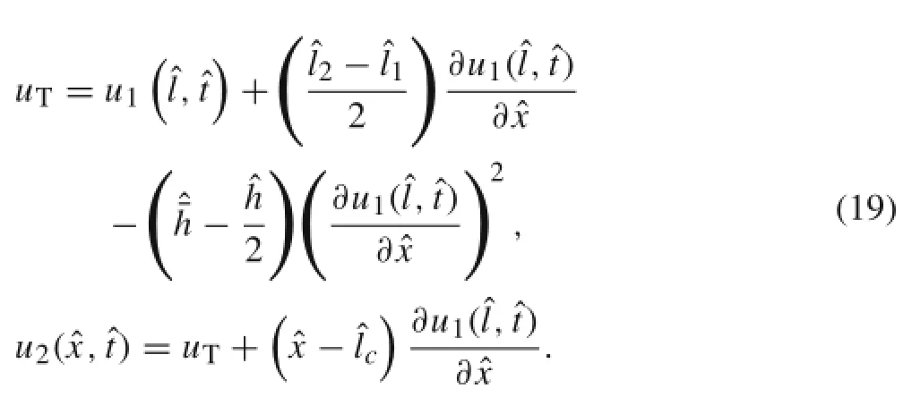
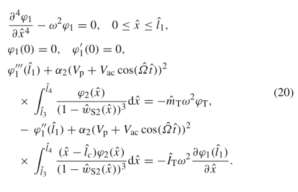
Considering Eq.(19),these equations become:
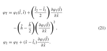
The homogeneous solution of Eq.(20)can be stated as

4 Primary resonance case
Assuming the deformation of the micro-cantilever around a static position as u(x,t),the displacement of the system can be described as

By substituting Eq.(23)into Eq.(10),expansion of the force and moment of electrostatic actuation around the static position up to third-order,and removing the pure static terms, the nonlinear equation of motion about the static position is obtained:
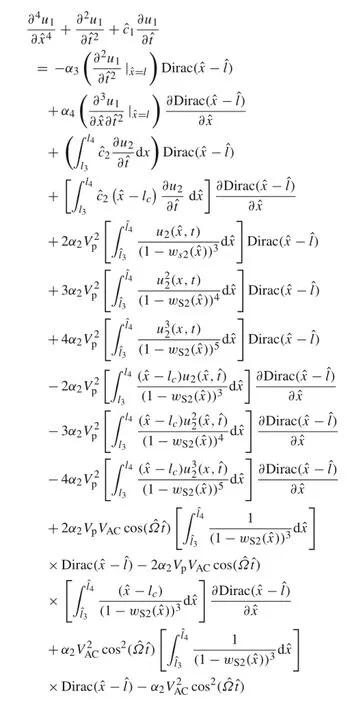
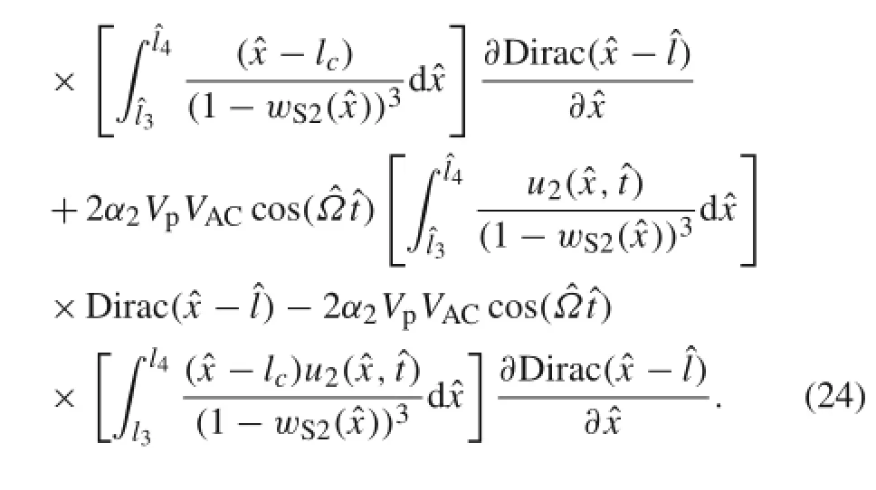
This equation can be discretized using the Galerkin method. To this goal firstly it is assumed that,whereϕ1andϕ2are the functions of linear mode shape of vibration about static deflection along the length of the microbeam and horizontal part of T-shaped body.Now,by substituting this assumptions into Eq.(24), and then multiplying the results by the linear mode shape and integration fromˆx=0 toˆx=1,one obtains:
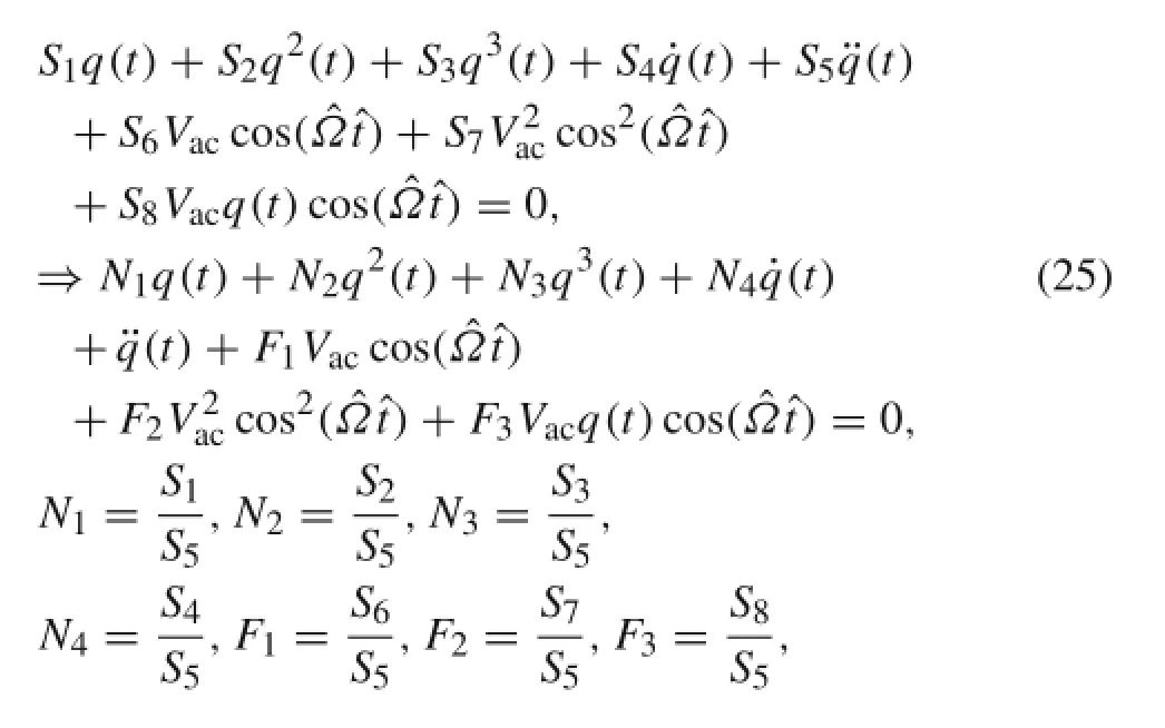
where the multipliers Si,i=1,2,...,8 are constant.These are described in Appendix 2.
Now it is assumed that[17]:

In order to balance the damping and the excitation forces with the nonlinear terms,it is assumed that the term including N4,i.e.,the term including the damping effect has order(ε2), and the term including power one of Vachas order(ε3).By this assumption and substituting Eq.(26)into Eq.(25),we find:
Order ε1:

Order ε2:

Order ε3:


where A(T1,T2)is a complex constant.By substituting Eq.(30)into Eq.(28):

where CC stands for the complex conjugate of the preceding terms.Eliminating the secular terms from q2demands that:

The particular solution of Eq.(30)is:

Now Eqs.(30)and(33)are substituted into Eq.(29),and then the excitation frequency is considered as Ω=ω+ε2σ, where σ is a detuning parameter.Keeping the terms that contain secular terms,we get:


Assuming γ=σT2−β,and separating real and imaginary parts in Eq.(35)yields

For non-transient solution a′=0,γ′=0,so,for the equilibrium solution one must set:

By squaring Eqs.(38)and(39)and adding the results,we obtain the frequency response equation:

From this equation,it is obvious that the maximum amplitude occurs when terms inside the parenthesis are equal to zero. So,the maximum amplitude and resonant shift are as follows

The stability of stationary solution may be studied by constructing the Jacobian matrix[21].
5 Subharmonic resonance case
If one assumes the frequency of AC voltage to be Ω=2ω+ ε2σ,and considers the term including power one of Vacin order(ε2),then secular terms will appear in the equation obtained by equating the terms with the same power of ε3. This means that the system has a subharmonic resonance frequency atIn this condition the term including power one of Vacwill be presented as an excitation term of order(ε2),where the equation of order ε will be the same as Eq.(27),so:
Order(ε2):

Order(ε3):

By substituting Eq.(30)into Eq.(43),one obtains

Eliminating the secular terms from q2demands that:

The particular solution of Eq.(45)is:

By substituting q1and q2from Eqs.(30)and(47),into Eq. (44),considering resonance frequency as Ω=2ω+ε2σ, and keeping the terms that contain secular terms,we get:
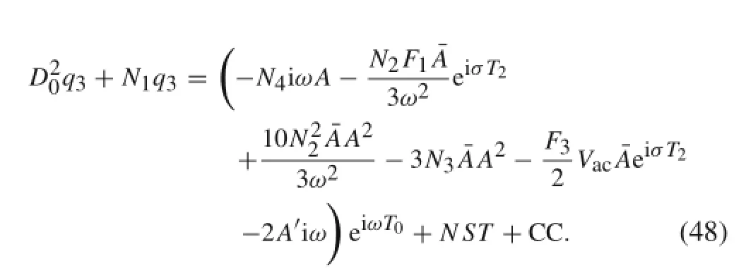
By expressing A in the polar formand substituting it into Eq.(48),elimination of secular terms yields:

Assuming γ=σT2−2β,and separating real and imaginary parts in Eq.(49)yields

For non-transient solution a′=0,γ′=0,so,for the equilibrium solution one must set:

By squaring Eqs.(51)and(52)and adding the results,we obtain the frequency response equation:

The stability of the stationary solution may be studied by constructing the Jacobian matrix[19].
6 Results and discussion
For a specific case of h2=0,l1=l3,l2=l4,the studied model would be reduced to a micro-plate connected to a micro-cantilever,as discussed in Ref.[41].Figures 3 and 4 show that under these conditions,the static deformation and the natural frequency are in good agreement with the previous work.In Fig.5,the diagram of vibrational amplitude with respect to the variations of frequency excitation is compared with the model in Ref.[41]for Q=ω1/c1=300,c2= 0,Vac=0.1,Vp=7.In the previous work,the results were obtained by the finite difference method,while this article used perturbation theory.This figure also shows acceptable agreement with the previous work.
Now we assume that the dimension of the horizontal part of the T-shaped mass is the same as the dimension of the rigid microplate connected to the end of the microcantilever in Ref.[41].Moreover,it is assumed that h1=1.5µm and the length of l2−l1,i.e.,the length of vertical part of the T-shaped mass,is equal to 0.025l,which is very small compared to the microbeam length.Other geometrical properties are considered to be the same as the properties of Ref.[41], see Fig.6.The mechanical behaviour of these two models are compared in Figs.7 and 8.Figure 7 shows that by increasing the DC voltage,a main difference is observed between theconsidered model in Ref.[41]and the model of our work. This difference is that the the microbeam with a T-shaped tip mass has a smaller deflection and a larger pull-in voltage. Pull-in voltage occurs when the static deflection and the natural frequency diagram lose their stability or,in other words, when the inclination of the curve is infinite.It is observered in Fig.8 that the microbeam with a T-shaped tip mass has a smaller nonlinear shift of resonance frequancy compared to the model of Ref.[41].

Fig.3 Maximum deflection of a microbeam with respect to the variation of DC voltage;where l1=250µm,l2=300µm,d=4µm,h= 1.5µm,h1=3µm for x=[0,l],and b=25µm for x=[l1,l2]
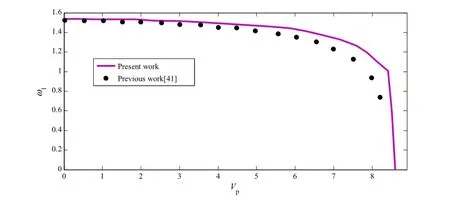
Fig.4 Variation of the first natural frequency with the variation of DC voltage,where l1=250µm,l2=300µm,d=4µm,h=1.5µm,h1= 3µm for x=[0,l],and b=25µm for x=[l1,l2]
These differences are due to the differences in the geometry of displacement of the rigid tip mass.When the rigid plate is connected to the end of a microcantilever according to Ref.[41],then as shown in Fig.6a the displacement along the whole length of the movable electrode increases by increasing the distance from the connection section between the microbeam and the rigid microplate.Figure 6b demonstrates that this behaviour is valid for the half length of the movable electrode and there is a reverse behaviour for other half length.Since the electrostatic force has a softening effect, this difference causes the static deflection and the nonlinear shift of the resonance frequency in the considered model to be smaller,and the pull-in voltage to be larger,than model considered in Ref.[41].Getting a larger pull-in voltage and smaller nonlinear shift of resonance frequency is a desir-able advantage for a resonance-shift-based sensor.It must be noted that in Figs.7 and 8 the length of the microbeam is shown as equal to the model considered in Ref.[35].This means that if an analyte layer is supposed to be deposited on a microbeam surface to obtain a mass or gas sensor,then by using a T-shaped tip mass,one obtains a sensor with a larger pull-in voltage and smaller nonlinear shift of resonance frequancy compared to Ref.[41],while the length and surface of the microbeam for depositing an analyte layer and the mass of the system are equal to the model of Ref.[41].
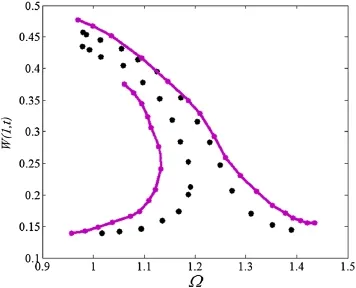
Fig.5 Frequency–response curve of the microbeam tip deflection for VDC=7 V and VAC=0.1 V;solid line belongs to this paper,and circle points belong to Ref.[41]
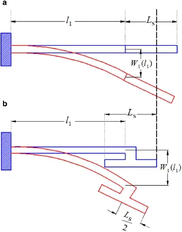
Fig.6 The geometry of displacement.a Considred model in Ref.[41]. b Considered model in this paper
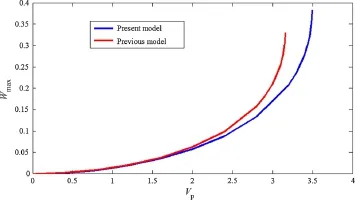
Fig.7 Comparison between maximum static deflection of the model considered in Ref.[35]and the model of our work
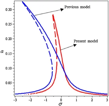
Fig.8 Comparison between the frequency response curve of the model considered in Ref.[41]and the model of this paper
In this article,change in the maximum deflection,pull-in voltage,fundamental natural frequency and primary resonance are studied in terms of different values for length of the horizontal section of T-shaped mass(Ls=l4−l3)and length of the vertical section of T-mass(Lp=l2−l1).The results are shown in Figs.9–17 for a system with c1=c2and geometric and physical parameters according to Table 1.
Figure 9 shows the effect of changing Lson the maximum deformation for different voltage values.As indicated in the above figure,increasing Lsdecreases the pull-in voltage and increases the static deformation.In fact,increasingthe Lsincreases the length which is subjected to electrostatic stimulation and consequently increases the electrostatic force,which causes further deformation in the microbeam.

Table 1 Geometric and physical parameters of the considered model
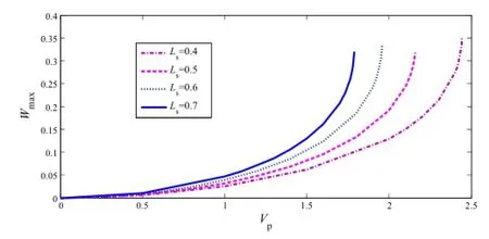
Fig.9 Maximum deflection variations of the system with respect to the variation of electrostatic voltage for different values of
Figure 10 shows the effect of changing length of the free–free microbeam(Ls)on the first natural frequency around the static position for different applied voltage values.As shown in the figure,increasing the amount of Lsdecreases the first natural frequency.This is because incrementing the Lsincreases the equivalent mass of the system and also increases softening effects due to increased electrostatic force.Both of these decrease the natural frequency.
Figure 11 shows the change in the maximum static deflection for different applied voltages and different Lpvalues. As indicated in the figure,by increasing Lp,the pull-in voltage remains almost constant and the maximum deformation slightly decreases due to the negligible curvature change at one end of microbeam,therefore there is a negligible change in the thickness.
Figure 12 shows the variations of the first natural frequency for different voltages and different Lpvalues.As shown in the figure,by increasing the Lp,the natural frequency first decreases and then increases.This is because increasing the Lpincreases the equivalent mass of the system, which decreases the natural frequency;however,increasing Lpincreases the bending stiffness,which increases the natural frequency.But,for small values of Lp,changes in the bending stiffness are negligible due to the small curvature of the beam at its end.Therefore,the mass has a greater impact on increasing the rigidity.As indicated in Fig.12,if Lpis significantly increased,so we observe that the effect of increasing the bending stiffness dominates the effect of the mass.

Fig.10 First natural frequency variations of the system with respect to the variations of electrostatic voltage for different values of Ls

Fig.11 Maximum deflection variations of the system with respect to the variations of electrostatic voltage for different values of Lp
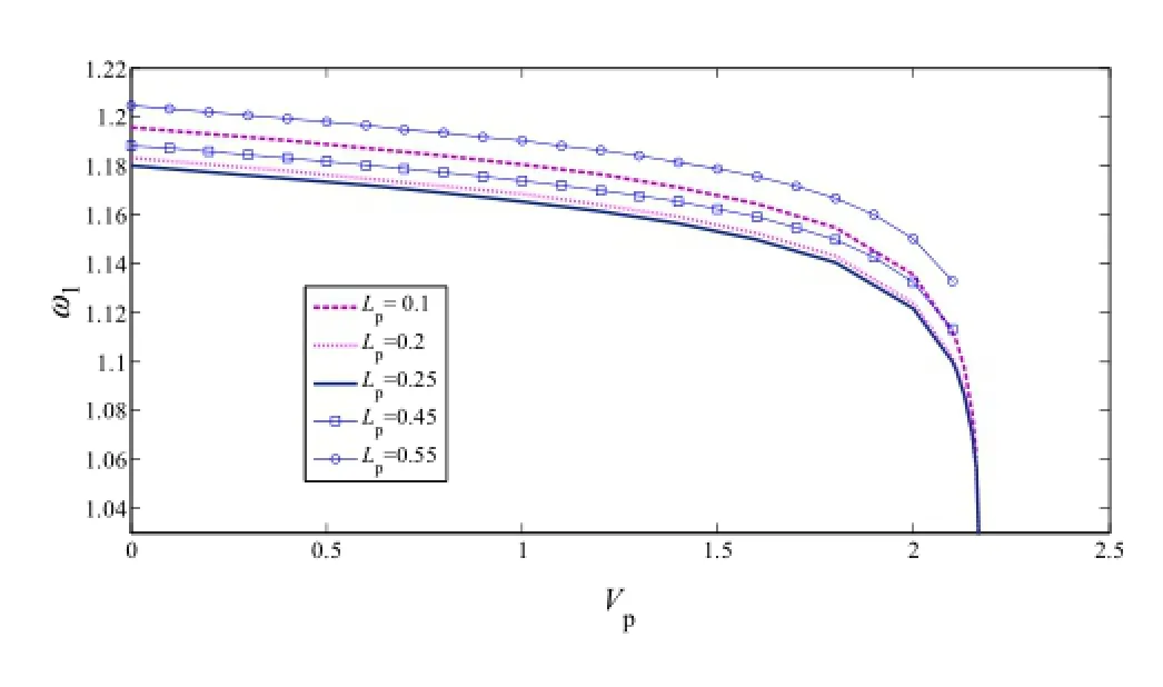
Fig.12 First natural frequency variations of the system with respect to the variations of electrostatic voltage for different values of Lp
Equation(41)shows that the maximum amplitude at primary resonance depends on F1,N4,ω,and Eq.(42)shows that the nonlinear shift of resonance frequency depends on the values of F1,N4,N5,andω,whereω is the natural frequency of the linear system,F1is caused by AC electrostatic actuation,N4is the result of the viscous damping and,N5represents the results of nonlinear electrostatic terms.Considering Eq.(34),the amount of N5is equal towhere N2and N3are due to nonlinear quadratic and cubic electrostatic terms,respectively.Equation(42)demonstrates that if the sign of N5is positive then the system will show a softening behavior,i.e.,Ω−ω<0.Previous works showedthat the electrostatic force has a softening effect[2,3,20], therefore it is expected that the sign of N5would be positive, which is also verified by Figs.13–15.Figures 13–15 show that by increasing the amount of Vpor Ls,the amount of N5increases and its variation is larger than its variation when Lpincreases.
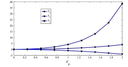
Fig.13 Variations of N2,N3,and N5for variations of Vp
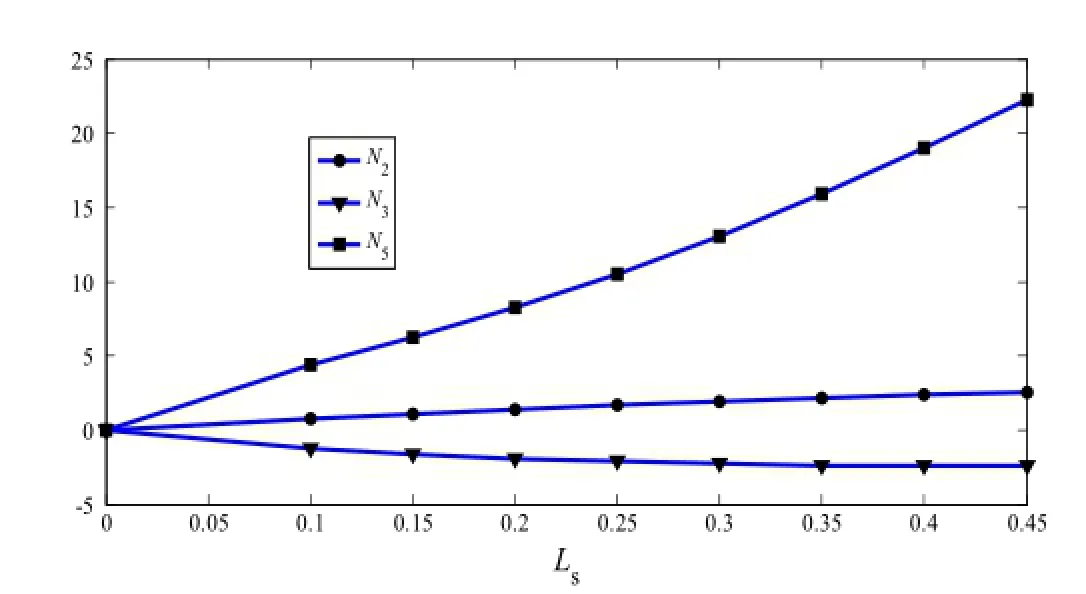
Fig.14 Variations of N2,N3,and N5for different values of Ls
Figures 16 and 17 illustrate the changes of the system’s equilibrium amplitude a for different values of Lsand Lpversus the change of σ at primary resonances.These figures show that the system has unstable solutions for negative values ofσ.It demonstrates that ifσ is positive,gradual decrease of σ causes the value of a to move toward the upper branch until it reaches the saddle-node bifurcation point A.Then, it jumps to the lower branch.This demonstrates that if the stationary solution is on the lower branch,then increasing σ slowly causes the value of a to move toward the lower branch until it reaches the saddle-node bifurcation point B. Afterwards,it jumps to the upper branch.
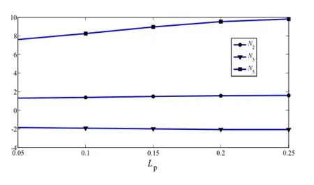
Fig.15 Variations of N2,N3,and N5for different values of Lp
Figure 16 demonstrates that when the value of Lsincreases,the nonlinear shift of resonance frequency and the maximum amplitude increase.This is due to the fact that according to Fig.14,the amount of N5increases and,from Fig.10,the amount of ω decreases.It must be noted that the amount of F increases due to an increase of the value of static deflection and thus,according to Eq.(42),Ω−ω increases. It must be mentioned that the amount of N4which is due to damping is almost constant.So,considering Eq.(41),with an increase of the value of F1and a decrease of the value of ω,the amplitude also increases.
Figure 17 shows that with an increase of the value of Lpthe nonlinear shift of the resonance frequency increases,while the maximum amplitude remains constant.This may be verified by considering Figs.11 and 12.These figures showed that with increases in the value of Lpthe frequency and static deflection changes were very small.Small variation of the value of static deflection induced small variation of thevalue of F.Therefore,considering Eq.(41),the maximum amplitude remains almost unchanged,but the resonance shift increases due to an increase of the value of N5.Comparing Figs.16 and 17 show that the variation of nonlinear shift of resonance frequency due to increasing the value of Lsis larger than its variation due to increasing the value of Lp. This result is found from the variation of the value of N5.
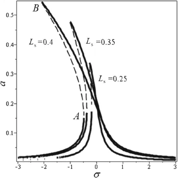
Fig.16 Frequency–response curve variations of the microbeam tip for different values of Lswhen Lp=0.1
The nonlinear shift of resonance frequency is an undesirable phenomena for a resonance-shift-based sensor.Considering Fig.16 if Ls=0.25,one observes a certain amount of nonlinear shift in the resonance frequency.It is noted that when the value of Lsdecreases,the nonlinear shift of resonance frequency decreases even more,but the amplitude of beam oscillation decreases,too.Although the amplitude of beam oscillation at the resonance peak is not directly related to a quantity under measurement in sensor applications,it is desirable for it to be as large as possible in order to facilitate tracking and measuring the change of resonance peak [47].Considering the above discussion,the system with Lsnear the value 0.25 is an optimum configuration which has an approximately linear response and has a large amplitude at the resonance peak.Figure 17 shows that the nonlinear shift of resonance frequency for a system with Ls=0.25 may be further decreased by decreasing the value of Lpwithout a main change on the value of the amplitude at the resonance peak.This is a desirable property,but it must be noted that for getting a rigid body motion for T-shaped tip mass,a very small value for Lpis not acceptable.It is recommended that Lpbe at least three times larger than microbeam thickness. By this assumption the function frequancy response for the optimum configuration will be as Fig.17.

Fig.17 Frequency–response curve variation of the microbeam tip for different values of Lp
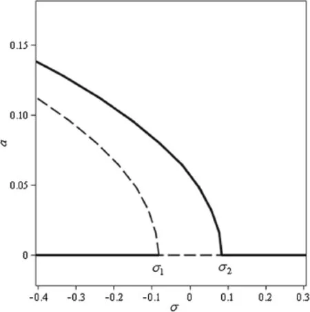
Fig.18 Variations of equilibrium solution a with respect to the variations of σ for system with Ls=0.4,Lp=0.1,VAC=0.1,Vp=2.1
Equation(41)shows that amplitude of the frequency response of a system at subharmonic resonance depends on the values of ω,N4,N5,K,where K is caused by AC electrostatic terms,and other parameters were described in the previous paragraphs.
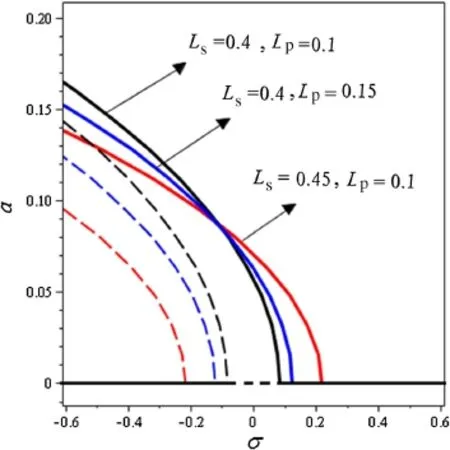
Fig.19 Variations of equilibrium solution a with respect to the variations of σ for different values of Lsand Lp
Figures 18 and 19 demonstrate the bifurcation diagram with respect to the variation of σ for different values of Lsand Lp,respectively,at subharmonic resonance.Figure 18 demonstrates that the system has two nontrivial branche which are approximately parallel.Since electrostatic force has a softening effect,the branches are inclined to the lef side.It shows that the lower branch of the nontrivial solution is unstable.This figure also shows that the trivial solution

7 Conclusion
In this study,the nonlinear static and dynamic responses to an electrostatic actuation were investigated for a T-shaped mass connected to the end of a micro-cantilever.In this configuration,it was assumed that the cantilever microbeam follows Bernoulli–Euler theory and movement of the T-shaped mass is a rigid body motion.An AC–DC voltage was applied between the horizontal section of the T-shaped mass and the opposite electrode.The equations of motion were found using a combination of the Hamilton principle and Newton’s method and the exact solution was provided for static deflection and mode shapes around the static position.Nonlinear equations of motion around the static position were discretized by the Galerkin method and the results were solved by the perturbation method.In order to verify the results,they were compared with previous work for a specific case.Results of verification showed that this study was in good agreement with the previous studies.Results showed that the pull-in voltage,static deflection,natural frequency and the steady state amplitude of vibration of a system at primary and subharmonic resonance depend on the geometry of the T-shaped mass.It has been shown that increasing the length of the horizontal part of the T-shaped mass increases the maximum static deflection and decreases the natural frequency and pull-in voltage.It has been observed that an increase of the length of the vertical part of the T-shaped mass decreases the static deflection and natural frequency. The results demonstrated that the frequency response function of the system depends on the values of natural frequency of the linear system,amplitude of the AC voltage,viscous damping and nonlinear electrostatic terms.It was shown that by increasing the length of the horizontal part of the T-shaped mass,the amount of maximum amplitude and nonlinear shift of the resonance frequency increased in the primary resonance case.It has been shown that the variations of static deflection,natural frequency and frequency response function of the system resulting from the change of the value of the length of the horizontal part of the T-shaped mass are larger than the variations resulting from the change of the value of its vertical length.
We conclude that attaching an electrode plate with a T-shaped configuration to the end of the cantilever microbeam results in a configuration with larger pull-in voltage and smaller nonlinear shift of the resonance frequency compared to the configuration in which the electrode plate is directly attached to it.This is a desirable advantage for resonance shift-based sensor and,therefore,the results of this paper may offer an optimization toward decreasing the nonlinear shift of resonance-shift-based sensors.
Appendix 1
Here the equation of motion and associated boundary conditions for a cantilever beam,shown in the figure below,is derived using the Hamilton principle.It is assumed that the length of the microbeam is l+ε0,and a concentrated force and moment,Fs,M at distance l from the clamped side are applied to it.According to the Hamilton principle[52]:
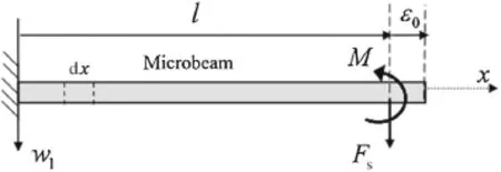
Fig.20 The microbeam under concentrated force and moment

where T,V,Wv,and Wfare the kinetic energy,potential strain energy,external work due to equivalent viscous damping and external work due to concentrated force and moment, respectively.The variation of these terms are as below (Fig.20)
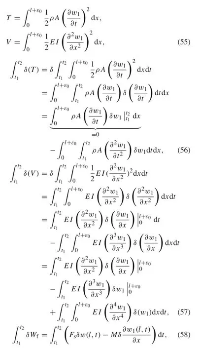
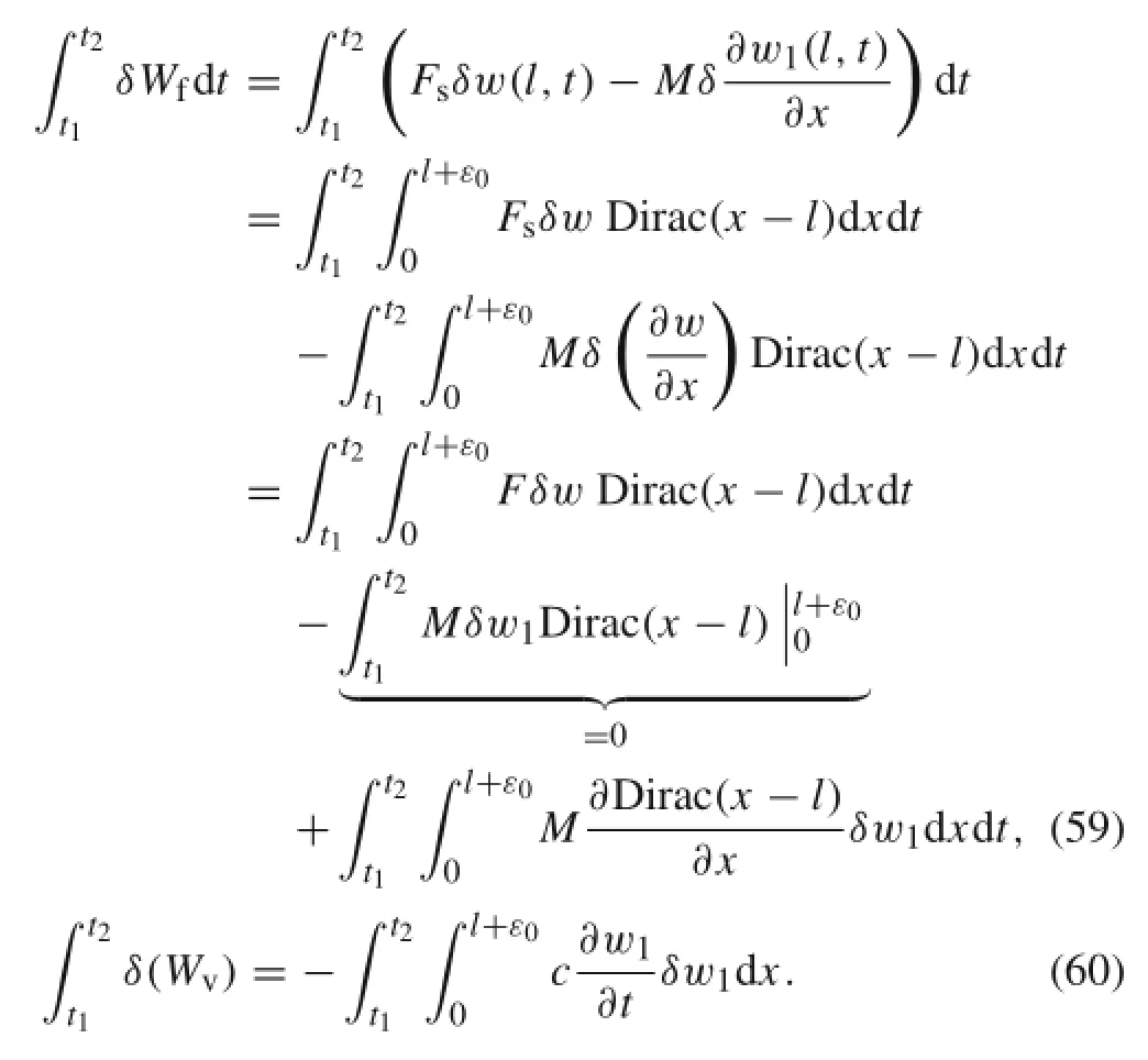
Now,if one substitutes Eqs.(56),(57),(59),and(60)into Eq.(54),the equation of motion for microbeam and associated boundary conditions will be:

It is clear that when ε0→ 0 i.e.,one assumes that the external force and moment are at the free boundary,then Eq.(61)results to Eq.(1).It can be considered that if one sets ε0=0,and then substitutes Eq.(58)instead of Eq.(59)into Eq.(54)then the equation of motion for microbeam will be:

Appendix 2


References
1.Gaura,E.,Newman,R.:Smart MEMS and Sensor Systems.Imperial College Press,London(2006)
2.Younis,M.I.:MEMS Linear and Nonlinear Statics and Dynamics. Springer,New York(2011)
3.Xu,L.,Jia,X.:Electromechanical coupled nonlinear dynamics for microbeams.Arch.Appl.Mech.77,485–502(2007)
4.Chaterjee,S.,Pohit,G.:A large deflection model for the pullin analysis of electrostatically actuated microcantilever beams.J. Sound Vib.322,969–986(2009)
5.Rasekh,M.,Khadem,S.E.:Pull-in analysis of an electrostatically actuated nano-cantilever beam with nonlinearity in curvature and inertia.Int.J.Mech.Sci.53,108–115(2011)
6.Zhang,Y.,Zhao,Y.:Numerical and analytical study on the pullin instability of micro-structure under electrostatic loading.Sens. Actuators A 127,366–380(2006)
7.Fang,Y.,Li,P.:Anew approach and model for accurate determination of the dynamic pull-in parameters of microbeam actuated by a step voltage.Micromech.Microeng.23,045010–045021(2013)
8.Huang,Y.T.,Chen,H.L.,Hsu,W.:An analytical model for calculating the pull-in voltage of micro cantilever beams subjected to tilted and curled effects.Microelectron.Eng.125,73–77(2014)
9.Rahaeifard,M.,Ahmadian,M.T.:On pull-in instabilities of microcantilevers.Int.J.Eng.Sci.87,23–31(2015)
10.Yin,L.,Qian,Q.,Wang,L.:Size effect on the static behavior of electrostatically actuated microbeams.Acta Mech.Sin.27,445–451(2011)
11.Kong,S.:Size effect on pull-in behavior of electro-statically actuated micro-beams based on a modified couple stress theory.Appl. Math.Model.37,7481–7488(2013)
12.Moeenfard,H.,Ahmadian,M.T.:Analytical modeling of static behavior of electrostatically actuated nano/micromirrors considering van der Waals forces.Acta Mech.Sin.28,729–736(2012)
13.Xiao,L.J.,Jie,Y.,Kitipornchai,S.:Pull-in instability of geometrically nonlinear micro-switches under electrostatic and Casimir forces.Acta.Mech.218,161–174(2011)
14.Boudjiet,M.T.,Bertrand,J.,Mathieu,F.,et al.:Geometry optimization of uncoated silicon micro-cantilever-based gas density sensors.Sens.Actuators B 208,600–607(2015)
15.Abdalla,M.M.,Reddy,C.K.,Waleed,F.F.,et al.:Optimal design of an electrostatically actuated microbeam for maximum pull-in voltage.Comput.Struct.83,1320–1329(2005)
16.Khushalani,D.G.,Dubey,V.R.,Bheley,P.P.,et al.:Design optimization and fabrication of micro cantilever for switching application.Sens.Actuators A 225,1–7(2015)
17.Younis,M.I.,Nayfeh,A.H.:Study of the nonlinear response of a resonant microbeam to an electric actuation.Nonlinear Dyn.31, 91–117(2003)
18.Abdel-Rahman,E.M.,Nayfeh,A.H.:Secondary resonances of electrically actuated resonant microsensors.J.Micromech.Microeng.13,491–501(2003)
19.Nayfeh,A.H.,Younis,M.I.:Dynamics of MEMS resonators under superharmonic and subharmonic excitations.J.Micromech.Microeng.15,1840–1847(2005)
20.Najar,F.,Nayfeh,A.H.,Abdel-Rahman,E.M.,et al.:Nonlinear analysis of MEMS electrostatic microactuators:primary and secondary resonances of the first mode.J.Vib.Control 16,1321–1349 (2010)
21.Najar,F.,Nayfeh,A.H.,Abdel-Rahman,E.M.,et al.:Dynamics and global stability of beam-based electrostatic microactuators.J. Vib.Control 16,721–748(2010)
22.Fu,Y.M.,Zhang,J.:Nonlinear static and dynamic responses of an electrically actuated viscoelastic microbeam.Acta Mech.Sin.25, 211–218(2009)
23.Zhang,Y.,Liu,Y.,Murphy,Kevin D.:Nonlinear dynamic response of beam and its application in nanomechanical resonator.Acta Mech.Sin.28,190–200(2012)
24.Younesian,D.,Sadri,M.,Esmailzadeh,E.:Primary and secondary resonance analyses of clamped–clamped micro-beams.Nonlinear Dyn.76,1867–1884(2014)
25.Ghayesh,M.H.,Farokhi,H.,Amabili,M.:Nonlinear behaviour of electrically actuated MEMS resonators.Int.J.Eng.Sci.71,137–155(2013)
26.Hajnayeb,A.,Khadem,S.E.:Nonlinear vibration and stability analysis of a double-walled carbon nanotube under electrostatic actuation.J.Sound Vib.331,2443–2456(2012)
27.Zamanian,M.,Hosseini,S.:Secondary resonances of a microresonator under AC–DC electrostatic and DC piezoelectric actuations. Struct.Eng.Mech.42,677–699(2012)
28.Raeisifard,H.,Zamanian,M.:Nikkhah Bahrami,M.,et al.:On the nonlinear primary resonances of a piezoelectric laminated micro system under electrostatic control voltage.J.Sound Vib.333,5494–5510(2014)
29.Zamanian,M.,Khadem,S.E.,Mahmoodi,S.N.:Analysis of nonlinear vibrations of a microresonator under piezoelectric and electrostatic actuations.Proc.Inst.Mech.223,329–344(2009)
30.Wang,H.,Meng,Q.:Analytical modeling and experimental verification of vibration-based piezoelectric bimorph beam with a tip-mass for power harvesting.Mech.Syst.Signal Process.36, 193–209(2013)
31.Aboelkassem,Y.,Nayfeh,A.H.,Ghommem,M.:Bio-mass sensor using an electrostatically actuated microcantilever in a vacuum microchannel.Microsyst.Technol.16,1749–1755(2010)
32.Khater,M.E.,Al-Ghamdi,M.,Park,S.,et al.:Binary MEMS gas sensors.J.Micromech.Microeng.24,065007(2014)
33.Shaat,M.,Abdelkefi,A.:Modeling of mechanical resonators used for nanocrystalline materials characterization and disease diagnosis of HIVs.Microsyst.Technol.22,305–318(2015)
34.Mokhtari-Nezhad,F.,Saidi,A.R.,Ziaei-Rad,S.:Influence of the tip mass and position on the AFM cantilever dynamics.Coupling between bending,torsion and flexural modes.Ultramicroscopy 109,1193–1202(2009)
35.Farrokh Payam,A.,Fathipour,M.:Study of the tip mass and interaction force effects on the frequency response and mode shapes of the AFM cantilever.Int.J Adv.Manuf.65,957–966(2013)
36.Mehdipour,I.,Erfani-Moghadam,A.,Mehdipour,C.:Application of an electrostatically actuated cantilevered carbon nanotube with an attached mass as a bio-mass sensor.Appl.Phys.13,1463–1469 (2013)
37.Wu,D.H.,Chien,W.T.,Chen,C.S.:Resonant frequency analysis of fixed-free single-walled carbon nanotube-based mass sensor.Sens. Actuators A 126,117–121(2006)
38.Rasekh,M.,Khadem,S.E.:Design and performance analysis of a nano-gyroscope based on electrostatic actuation and capacitive sensing.J.Sound Vib.332,6155–6168(2013)
39.Mojahedi,M.,Ahmadian,M.T.,Firoozbakhsh,K.:The influence of the intermolecular surface forces on the static deflection and pull-in instability of the micro/nano cantilever gyroscopes.Compos.Part B 56,336–343(2014)
40.Alsaleem,F.M.,Younis,M.I.,Ouakad,H.M.:On the nonlinear resonances and dynamic pull-in of electrostatically actuated resonators.J.Micromech.Microeng.19,045013(2009)
41.Nayfeh,A.H.,Ouakad,H.M.,Najar,F.,et al.:Nonlinear dynamics of a resonant gas sensor.Nonlinear Dyn.59,607–618(2010)
42.Ouakad,H.M.:The response of a micro-electro-mechanical system (MEMS)cantilever-paddle gas sensor to mechanical shock loads. J.Vib.Control 21,2739–2754(2015)
43.Zamanian,M.,Karimiyan,A.:Analysis of the mechanical behavior of a doubled microbeam configuration under electrostatic actuation.Int.J.Mech.Sci.93,82–92(2015)
44.Zamanian,M.,Karimiyan,A.,Hosseini,S.A.A.,et al.:Nonlinear vibration analysis of a-shaped mass attached to a clamped-clamped microbeam under electrostatic actuation.Proc.Inst.Mech.Eng.C (2016)(in press).doi:10.1177/0954406215627832
45.Tadayon,M.A.,Rajaei,M.,Sayyaadi,H.,et al.:Nonlinear dynamics of microresonators.J.Phys.Conf.Ser.34,961–966(2006)
46.Sayyaadi,H.,Tadayon,M.A.,Eftekharian,A.A.:Micro resonator nonlinear dynamics considering intrinsic properties.J.Sci.Iran. Trans.B Mech.Eng.16,121–129(2009)
47.Younis,M.I.,Alsaleem,F.:Exploration of new concepts for mass detection in electrostatically-actuated structures based on nonlinear phenomena.J.Comput.Nonlinear Dyn.4,021010(2009)
48.Zamanian,M.,Khadem,S.E.:Analysis of thermoelastic damping in microresonators by considering the stretching effect.Int.J. Mech.Sci.52,1366–1375(2010)
49.Nayfeh,A.H.,Younis,M.I.:Modeling and simulations of thermoelastic damping in microplates.J.Micromech.Microeng.14, 1711–1717(2004)
50.Abdel-Rahman,E.M.,Younis,M.I.,Nayfeh,A.H.:Characterization of the mechanical behavior of an electrically actuated microbeam.J.Micromech.Microeng.12,759–766(2002)
51.Nayfeh,A.H.,Younis,M.I.:A new approach to the modeling and simulation of flexible microstructures under the effect of squeezefilm damping.J.Micromech.Microeng.14,170–181(2004)
52.Hagedorn,P.,DasGupta,A.:Vibrations and Waves in Continuous Mechanical Systems.Wiley,Chichester(2007)
✉ M.Zamanian zamanian@khu.ac.ir
1Department of Mechanical Engineering,Faculty of Engineering,Kharazmi University,P.O.Box 15719-14911, Tehran,Iran
19 April 2016/Revised:28 May 2016/Accepted:8 June 2016/Published online:2 September 2016
- Acta Mechanica Sinica的其它文章
- Closed-form solutions for free vibration of rectangular FGM thin plates resting on elastic foundation
- MoM-based topology optimization method for planar metallic antenna design
- Dilation and breakage dissipation of granular soils subjected to monotonic loading
- A semi-analytical approach for calculating the equilibrium structure and radial breathing mode frequency of single-walled carbon nanotubes
- Time-delay identification for vibration systems with multiple feedback
- Plaque components affect wall stress in stented human carotid artery:A numerical study

