Turbulent heat transfer and pressure loss in a square channel with discrete broken V-rib turbulators*
Promthaisong PITAK,Eiamsa-ard PETPICES,Jedsadaratanachai WITHADA,Eiamsa-ard SMITH
1.Faculty of Engineering,Mahanakorn University of Technology,Bangkok,Thailand,E-mail:k.pitak_pts@hotmail.com
2.Faculty of Industrial Technology,Phetchaburi Rajabhat University,Phetchaburi,Thailand
3.Faculty of Engineering,King Mongkut's Institute of Technology Ladkrabang,Bangkok,Thailand
Turbulent heat transfer and pressure loss in a square channel with discrete broken V-rib turbulators*
Promthaisong PITAK1,Eiamsa-ard PETPICES2,Jedsadaratanachai WITHADA3,Eiamsa-ard SMITH1
1.Faculty of Engineering,Mahanakorn University of Technology,Bangkok,Thailand,E-mail:k.pitak_pts@hotmail.com
2.Faculty of Industrial Technology,Phetchaburi Rajabhat University,Phetchaburi,Thailand
3.Faculty of Engineering,King Mongkut's Institute of Technology Ladkrabang,Bangkok,Thailand
Turbulent periodic flow,heat transfer,friction loss and thermal enhancement characteristics in a three-dimensional horizontal square channel with broken V-ribs (B-VR) are numerically investigated.The computations are based on the finite volume method,and the SIMPLE algorithm with QUICK scheme is implemented.The B-VR were installed on both sides of a plate which was diagonally placed in a square channel to produce longitudinal vortex flows through the tested section.Effects of different open corner ratios (d/ H=0,0.01,0.02,0.03,0.04 and 0.05) on heat transfer and pressure loss in the channel and the results of the B-VR are studied.The pitch ratio(PR=p/ H)and blockage ratio (BR=p/ H)of B-VRs were fixed at 1.0 and 0.15,respectively.As compared with the channel without V-rib,the one with B-VRs possessed considerably higher heat transfer and friction loss.It is observed that apart from the rise of Reynolds number,the reduction of the open corner ratios leads to an increase in the Nusselt number and friction factor due to the weaker turbulence and lower resistance to the flow.According to the computational results for B-VRs,the optimum thermal enhancement is found atd/ H=0.
channel,periodic flow,heat transfer,friction loss,broken V-ribs
Introduction
Several techniques have been employed to improve heat transfer in heat transfer devices for more compact heat transfer system and cost/energy saving.One of the most effective methods of enhancing the heat transfer rate in a smooth channel is the use of ribbed/baffled surfaces with in line or staggered arrays.This is because the rib/baffle help to interrupt the hydrodynamic and thermal boundary layers and to induce a recirculation zone or vortices flow behind the rib.The flow reattachment downstream of the rib/ baffle gives rise to the washing up or down the channel walls leading to the increase in the heat transfer rate.In general,the modified surfaces induce seconda-ry flows which effectively enhance heat transfer with an increase of friction loss penalty.Rib/Baffle roughened surfaces are widely used in engineering applications especially,for cooling gas turbine blades.
Most of researches relevant to heat transfer enhancement by ribbed/baffled surfaces have focused on optimizing geometric parameter and arrangement of ribs/baffles to yield great heat transfer enhancement with reasonable friction loss.Tang and Zhu[1]used the shear stress transport (SST)k-ω turbulence model to predict the flow (vortex structure and turbulent mixing) and heat transfer characteristics in the rectangular channel with inclined broken ribs for three kinds of rib arrays has been conducted.They observed that the heat transfer of the inclined broken ribbed channel was enhanced up to 230% compared to those smooth duct due to the effect of the co-rotating longitudinal vortices.Again,Tang and Zhu[2]reported the effect discontinuous crossed ribs and grooves on the thermo-hydraulic performance characteristics in a rectangular channel by using SST k-ω turbulencemodel.The overall thermo-hydraulic performances for ribbed-grooved channel was increased up to 13.6% higher than those the ribbed channel.Boulemtafes-Boukadoum and Benzaoui[3]studied the heat transfer enhancement in a solar air heater with artificially roughened absorber using k-εRNG,k-εRZ,k-ω standard,and k-ωSST turbulence model.Sara et al.[4]reported that the use of solid ribs with and angle of attack of 90oto the axial flow resulted in hot zones in the wake of the ribs due to the recirculation flow with low speed.They showed that as the angle of attack decreased,the hot zones became smaller.The idea was adopted to design V-shaped ribs in several research works.Yongsiri et al.[5]studied the effect of the channel with inclined detached-ribs on the heat transfer,pressure loss and thermal enhancement behaviors.They found that at high Reynolds number,the inclined ribs with θ=60oand 120oyield comparable heat transfer rates and thermal enhancement factors which were higher than those given by the ones with other angles.On the other hand,at low Reynolds number,the effect of rib attack angle was insignificant.Eiamsa-ard et al.[6]studied the effect of triangular wavy baffles on the heat transfer,friction factor and thermal performance in a channel with three different angles of attack.They found that the highest thermal performances achieved by using baffles with the attack angles of 30o,45oand 60oare 2.3,2.2 and 1.88,respectively.Wongcharee et al.[7]predicted the influence of the shaped ribs (rectangular rib,triangular rib,cylindrical rib,concave-concave rib,convexconcave rib,long convex-short concave rib and long concave-short concave rib) on the thermal performance characteristics in a channel by using SST k-ω and RNG k-εturbulence-models.They reported that the triangular rib provided higher heat transfer rate than the cylindrical rib does up to 29.3% while the cylindrical rib offers higher thermal performance factor than the triangular rib does around 9.6%.Similarly,Sri Harsha et al.[8],Tanda[9]and Gupta et al.[10]found that V-broken ribs gave significantly higher thermal performance than the continuous ribs did.Ary et al.[11]studied the influence of the inclined perforated baffles on the heat transfer and flow structures in a rectangular channel for different types of baffles.Details of effects of 60oV-shaped baffles on thermal and friction characteristics in a channel were reported by Promvonge[12].Liu and Chung[13]used the largeeddy simulation (LES) to investigate the flows between two ribs at various separations and compare the local heat transfer coefficient (LHTC) on the cavity bottom.Again,Liu et al.[14]performed the effect of two opposite rib-roughened walls on the thermal characteristics in a rectangular channel at different channel aspect ratios (W/ H =0.25,0.5 and 1).They reported that the channels with W/ H =0.5 or 1,the heat transfer decreases along the rib axes because of the rib-induced secondary flow that moving from the left-hand side to the right-hand side.
As mentioned above,the heat transfer enhancement is accompanied by an increased friction loss.Energy lost caused by friction may exceed that gained from increased heat transfer.Therefore,for practical applications,it needs to determine overall thermal performance as a net benefit by comparison of the heat transfer at constant pumping power.Another approach to improve thermal performance is reducing friction loss due to the flow resistance.Sara et al.[15]investigated the heat-transfer enhancement and the corresponding pressure drop over a flat surface in a channel flow due to perforated blocks with different inclination angles.As compared with solid blocks,the inclined perforated blocks possessed considerably better overall thermal performance because of the higher heat transfer enhancement and the lower pressure drop too.The higher heat transfer enhancement was gained because the inclined perforated blocks induced the jet-like flow toward the heated surface in the wake of the blocks while the lower pressure drop was caused by the lower resistance to the flow as the existing holes allowed the flow to pass through the blocks.Yang and Hwang[16]examined numerically heat transfer characteristics in a rectangular duct with slit and solid ribs on one wall and reported that the slit rib performed better than the solid one.Liou et al.[17]reported heat transfer enhancement by vortex generators and ribs in first passage of a two pass square channel.The effects of the vortex generators and rib configurations (60ooblique rib,“V” shaped ribs of 60oand 45oand delta wing) were examined.Among the rib configurations considered,it was the 45oV-shaped rib gave the highest heat transfer enhancement while the delta wing configuration gave the lowest heat transfer augmentation.However,the delta wing configurations made superior overall thermal performance because of the lower pressure drops.
Most of the investigations on turbulent flow,cited above,have considered only the heat transfer characteristics for blockage ratio and spacing ratio values for broken V-ribs (B-VR) with open corner ratios.In the present work,the numerical computations for three dimensional turbulent periodic channel flows over V-ribs mounted on both sides of a plate were examined with the main aim being to improve the flow conditions and thermal enhancement by allowing some portions of flow through the spaces on broken V-ribs (B-VR) in order to reduce the flow resistance.The spaces on the broken V-ribs (B-VR) were created by partial opening corner of V-ribs.The investigation was carried on via numerical simulation to examine periodic fluid flow,heat transfer,friction lossand thermal enhancement characteristics in channels equipped with broken V-ribs with different open corner ratios (d/ H=0,0.01,0.02,0.03,0.04 and 0.05).
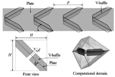
Fig.1 B-VRs geometry and computational domain of the periodic flow
1.Flow description
1.1 Geometry and configuration of B-VRs and channel
The system of interest is a square channel with B-VRs.The B-VRs were installed on both side of the plate which was diagonally placed in a channel as shown in Fig.1.Geometry of a channel with B-VRs for the fully developed flow has an entrance length of 10H ,test section of 14H ,and exit length of 2H.The height of the B-VRs(b),the height of the channel(H)and the rib pitch(p)were kept at 0.05 m,0.05 m and 0.05 m,respectively.These resulted in constant pitch ratio(PR=p/ H)and blockage ratio(BR=p/ H)of 1.0 and 0.15,respectively.The angle of attack(α)was fixed at 45owhile the open corner ratios(d/ H),was varied from 0 to 0.05 (0,0.01,0.02,0.03,0.04 and 0.05).The flow was assumed to be under a periodic flow condition in which the velocity field repeats itself from one cell to another. The simulation was performed using the concept of periodically fully developed flow which was introduced by Webb and Ramadhyani[18]and Kelkar and Patankar[19].
1.2 Boundary condition
Periodic boundary condition was applied throughout the flow domain.Constant mass flow rate of air with 300 K (Pr=0.7)was assumed in the flow direction rather than constant pressure drop due to periodic flow condition.A non-uniform mesh with grid adoption fory+<5at adjacent wall region is used to resolve the laminar sub-layer with a refined mesh density in the regions near the wall boundaries.The inlet and outlet profiles for the velocities were identical.The physical properties of the air were assumed to remain constant at average bulk temperature.Impermeable boundary and no-slip wall conditions were implemented over the square channel walls as well as the ribs.All the square channel walls were subjected to a constant heat flux of 600 W/m2while the rib surfaces were subjected to an adiabatic wall condition.
2.Mathematical foundation
The numerical model for fluid flow and heat transfer in a square channel was developed under the following assumptions:steady three-dimensional fluid flow and heat transfer,the flow was turbulent and incompressible,constant fluid properties,body forces and viscous dissipation were ignored.And negligible radiation heat transfer.Based on the above assumptions,the square duct flow is governed by the continuity,the Navier-Stokes equations and the energy equation.
Continuity equation

Momentum equation

Energy equation

where Γ is the thermal diffusivity and is given by

The phenomena under consideration are governed by the steady two-dimensional form of the continuity and the time-averaged incompressible Navier-Stokes equations.The realizable k-ε turbulent model was used with enhanced wall functions for the near-wall treatment.

and
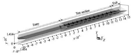
Fig.2 Geometry of a channel with B-VRs at d/ H =0.05and computational domain of the fully developed flow
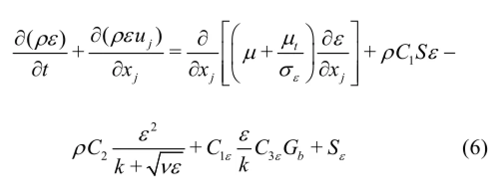
where

and
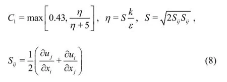
the model constants are given as follows:

where Gkand Gbare the production of turbulence kinetic energy due to the mean velocity gradients and buoyancy,respectively.The parameterYmis the contribution of the fluctuating dilatation in compressible turbulence to the overall dissipation rate.σkand σεare the turbulent Prandtl numbers forkandε,respectively.The governing equations were discretized by the QUICK differencing scheme,decoupling with the SIMPLE algorithm and solved using a finite volume approach[20].The energy equation and other were considered to be converged when the normalized residual values were less than 10-9and 10-5,respectively.
Four parameters of interest in the present work are the Reynolds number,friction factor,Nusselt number and thermal enhancement factor.The Reynolds number is defined as

The friction factor,fis computed by pressure drop,∆pacross the length of the periodic channel,L as

The average Nusselt number can be obtained by

The thermal enhancement factor(η)is given by

where Nu0and f0stand for Nusselt number and friction factor for the smooth channel,respectively.
For the present work the use of grid system of 320 000 cells resulted in variation less than 0.2% for Nuandfvalues.The comparable results were obtained when cell numbers were increased from 320 000 to 800 000[21].Considering both convergent time and solution precision,the grid system of 320 000 cells was adopted for the current computational model.
3.Result and discussion
3.1 Fully developed flow
Understanding of a fully developed periodic profile condition in the baffled tube is needed before discussing the results.The fully developed periodic flow conditions in the channel mounted repeatedly with B-VRs can be displayed by considering the axial u/ u0distribution as depicted in Figs.2 and 3.The profile of velocity is explained into 2 forms.First,the velocity profile with structures similar to other modules but values not equal as shown in the figure atx/ H=2-4,is called “periodic flow profile”.Second,the profile that equal on both structures and values is called “fully developed periodic flow profile” when thex/ H≥7.In addition,the fully developed periodic heat transfer profiles are obvious at thex/ H≥7as seen in Fig.4.

Fig.3 Velocity profile in a channel with B-VRs at d/ H=0.05 and Re =8000(α=45o,BR =0.15,PR =1.0,y/ H =3/4,z/ H =1/2)

Fig.4 Nusselt number profile in a channel with B-VRs at d/ H =0.05and Re =8000(α=45o,BR =0.15,PR =1.0,y/ H =3/4,z/ H=1/4)
3.2 Validation test of the smooth channel
Verification of the heat transfer and friction factor of the square channel (the channel without B-VRs)is performed by comparing with the previous values under a similar condition as shown in Fig.5.The present numerical smooth channel result is found to be in excellent agreement with exact solution values obtained from the open literature[22]for both the Nusselt number and the friction factor,less than ±5.3%and ±4.8%maximum deviations,respectively.This provides a strong confidence in further investigation of the channel flow over the B-VRs.
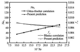
Fig.5 Verification of Nusselt number and friction factor for smooth square channel

Fig.6 Relationship between of Nu/ Nu0andRe(α=45o,BR =0.15,PR=1.0,V-Upstream)
3.3 Heat transfer
The effect of B-VRs on the heat transfer rate in smooth channel is presented in Fig.6.In the figure,it can be observed that the Nusselt number ratio(N u/ Nu0)decreases with the rise in Reynolds number for e B-VRs consistently yields higher heat transfer rate than the smooth channel due to the effectiveness in disruption of the boundary layer.The variation of Nu/ Nu0ratio with d/ H at various Revalues is also depicted in the figure.At the given Reynolds number,Nu/ Nu0ratio decreases with the increase of d/ H.For the range considered,the use of B-VRs resulted in heat enhancement from 3.54 to 5.39 times of those in the smooth square channel.The maximum of Nu/ Nu0ratio (5.39) was achieved by using the ribs with d/ H =0(the ribs without opening corner) at Re= 3 000.Figure 7 displays the flow structure and contour plots of temperature field in longitudinal planeson a square channel walls with B-VRs at d/ H=0,0.01,0.02,0.03,0.04 and 0.05 forRe=3000.

Fig.7 Flow structure and temperature distributions in a channel with B-VRs at different open corner ratios
The results revealed that as d/ Hincreased,the intensities of vortex and turbulent flows decreased.In addition,the centers of vortices shifted away from channel walls to open corner regions.These resulted in smaller vortex/recirculation flow behind the baffles(Fig.7(b)-7(f)) and poorer fluid mixing near channel walls,as could be observed from the longer bands of thermal boundary layers along the channel walls.Local Nusselt number contours for a channel walls with B-VRs at different d/ Hbetween 0 and 0.05 are presented in Fig.8.For all cases,heat transfer was intense around the middle of the wall with the help of ribs by inducing impingement flows toward to the areas.However,heat transfer became poorer around the corners as the hot zones.As the d/ Hincreased,the high heat transfer area became smaller.The explanation may be that the opening corner with largerd/ Hpossess smaller flow blockage and disturbing effects,thus they allow the fluid to flow through the opening corners more easily,resulting in weaker vortex/ turbulence and fluid mixing and consequently less efficient heat transfer.
3.4 Pressure loss
The variation of the friction factor ratio,f/f0with Reynolds number values for various d/ His depicted in Fig.9.In the figure,it is interesting to note that the friction factor tends to increase with the rise of Reynolds number for all B-VRs cases.The use of the B-VRs leads to considerable increase in friction factor in comparison with the smooth channel with no B-VRs.The variation of the average f/f0ratio with d/ H at variousRevalues is also presented.At the sameRe,f/f0ratio decreased with the increase of d/ H ,as the larger d/ Hpossessed,the lower the resistance to the flow.For the range considered,the use of B-VRs resulted in increased friction factor from 28.03-37.89 times of those in the smooth square channel.The lowest f/f0ratio (28.03) was caused by using the B-VRs with d/ Hof 0.05 while the maximumf/f0ratio (37.89) was found at d/ H=0(the ribs without open corner) for Re =3000.
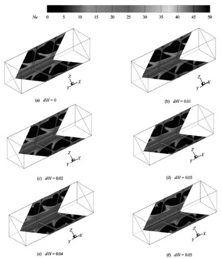
Fig.8 Local Nusselt number distributions in a channel with B-VRs at different open corner ratios for Re=3000
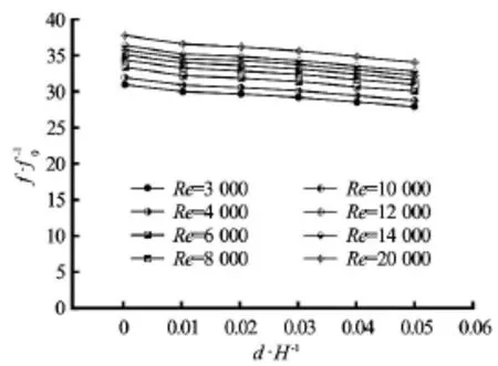
Fig.9 Relationship between of f/f0and d/ H (α=45o,BR =0.15,PR=1.0,V-Upstream)
3.5 Thermal enhancement evaluation
Figure 10 exhibits the variation of thermal enhancement factor (TEF) at the same pumping power associated with the use of the B-VRs.In the figure,the thermal enhancement factor tends to increase with the rise of Reynolds number.For all cases,TEFs were higher than unity (varied between 1.16 and 1.6) indicating that these cases are advantageous with respect to smooth channel without B-VRs.Evidently,the TEF as an overall thermal enhancement decreased with increasing d/ H .In fact,the B-VRs with larger d/ Hcaused lower friction loss and gave poorer heat transfer enhancement.The effect ofd/ Hon TEF signified that the influence of decreasing heat transfer enhancement was more significant than that of decreasing friction loss,when d/ Hincreased.For range determined,the maximum TEF of 1.6 was achieved by using the ribs withd/ H=0(the ribs without open corner) atRe =3000.This suggests that theB-VRs should be used to obtain higher thermal enhancement rather than the smooth channel.
3.6 Comparison with previous works
The comparison of TEF in a channel mounted with the discrete broken V-ribs (B-VR) and other rib turbulators in past reported[23,24]was demonstrated in Fig.11.The typical 90orib turbulators with p/ H= 1.0,e/ H =0.2of Peng et al.[23]and the out-phase 45oZ-baffle turbulators with p/ H =2.0,e/ H=0.2 of Sriromreun et al.[24]were chosen for comparison at the similar test conditions with consideration by using the air as the working fluid (P r =0.7).In this comparison,the TEF was evaluated and performed under the same pumping power.The figure presented that the TEF increases with decreasing Reynolds number for all turbulators.Comparatively,the TEF for the present work (discrete broken V-ribs (B-VR)) performs higher TEF than the typical 90oribs do[23]due to the lower friction near the channel wall while it performs slightly higher TEF than the 45oZ-baffle does at the low Reynolds number (Re<5000)and lower than the 45oZ-baffle does for higher Reynolds number above 5 000.
4.Conclusion
The turbulent heat transfer in a square channel fitted with B-VRs elements has been studied using numerical simulation.The results show that the B-VRs induced longitudinal vortex flows toward the channels,resulting in considerable heat transfer enhancement which accompanied by friction loss penalty.However,the increase of d/ H resulted in the decrease of heat transfer enhancement and also friction loss.The order of enhancement is about 346%-539% for using the B-VRs.However,as expected,the augmentation is associated with enlarged friction loss ranging from 28.03-37.89 times above the smooth channel.All ribs gave TEF above unity,indicating the net benefit from the point of view of energy saving of the enhancement approach.The thermal enhancement factor for VRs with d/ H =0(the ribs without open corner)is around 1.6 higher than that for the smooth channel.
[1]TANG X.Y.,ZHU D.S.Flow structure and heat transfer in a narrow rectangular channel with different discrete rib arrays[J].Chemical Engineering and Processing:Process Intensification,2013,69(7):1-14.
[2]TANG Xin-yi,ZHU Dong-sheng.Experimental and numerical study on heat transfer enhancement of a rectangular channel with discontinuous crossed ribs and grooves[J].Chinese Journal of Chemical Engineering,2012,20(2):220-230.
[3]BOULEMTAFES-BOUKADOUM A.,BENZAOUI A.CFD based analysis of heat transfer enhancement in solar air heater provided with transverse rectangular ribs[J].Energy Procedia,2014,50:761-772.
[4]SARA O.N.,PEKDEMIR T.and YAPICI S.et al.Enhancement of heat transfer from a flat surface in a channel flow by attachment of rectangular blocks[J].International Journal Renewable Energy Research,2001,25(7):563-576.
[5]YONGSIRI K.,EIAMSA-ARD P.and WONGCHAREE K.et al.Augmented heat transfer in a turbulent channel flow with inclined detached-ribs[J].Case Studies in Thermal Engineering,2014,3:1-10.
[6]EIAMSA-ARD S.,PATTANAPIPAT S.and PROMVONGE P.Influence of triangular wavy baffles on heat and fluid flow characteristics in a channel[J].Journal of Mechanical Science and Technology,2013,27(7):2199-2208.
[7]WONGCHAREE K.,CHANGCHAROENY W.and EIAMSA-ARD S.Numerical investigation of flow friction and heat transfer in a channel with various shaped ribs mounted on two opposite ribbed walls[J].International Journal of Chemical Reactor Engineering,2011,9(1):566-572.
[8]SRI HARSHA V.,PRABHU S.V.and VEDULA R.P.Influence of rib height on the local heat transfer distribution and pressure drop in a square channel witho90continuous ando60V-broken ribs[J].Applied Thermal Engineering,2009,29(11-12):2444-2459.
[9]TANDA G.Heat transfer in rectangular channels with transverse and V-shaped broken ribs[J].InternationalJournal of Heat and Mass Transfer,2004,47(2):229-243.

Fig.10 Relationship between the thermal enhancement factor and d/ H (α=45o,BR =0.15,PR =1.0,V-Upstream)
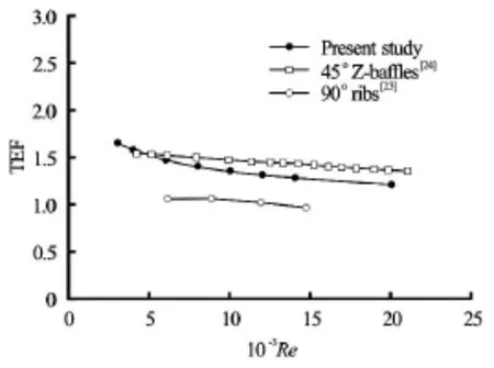
Fig.11 Comparison of thermal performance of the present discrete broken V-ribs (B-VR) with previous work
[10]GUPTA A.,SRIHARSHA V.and PRABHU S.V.et al.Local heat transfer distribution in a square channel with 90° continuous,o90saw tooth profiled ando60broken ribs[J].Experimental Thermal and Fluid Science,2008,32(4):997-1010.
[11]ARY B.K.P.,LEE M.S.and AHN S.W.et al.The effect of the inclined perforated baffle on heat transfer and flow patterns in the channel[J].International Communications in Heat and Mass Transfer,2012,39(10):1578-1583.
[12]PROMVONGE P.Heat transfer and pressure drop in a channel with multipleo60V-baffles[J].International Communications in Heat and Mass Transfer,2010,
[13]LIU C.H.,CHUNG T.N.H.Forced convective heat tran-37(7):835-840.sfer over ribs at various separation[J].International Journal of Heat and Mass Transfer,2012,55(19-20):5111-5119.
[14]LIU J.,GAO J.and GAO T.et al.Heat transfer characteristics in steam-cooled rectangular channels with two opposite rib-roughened walls[J].Applied Thermal Engineering,2013,50(1):104-111.
[15]SARA O.N.,PEKDEMIR T.and YAPICI S.et al.Heattransfer enhancement in a channel flow with perforated rectangular blocks[J].International Journal of Heat and Fluid Flow,2001,22(5):509-518.
[16]YANG Y.T.,HWANG C.W.Numerical calculations of heat transfer and friction characteristics in rectangular ducts with slit and solid ribs mounted on one wall[J].Numerical Heat Transfer Part A:Applications,2004,45(4):363-375.
[17]LIOU T.M.,CHEN C.C.and TSAI T.W.Heat transfer and fluid flow in a square duct with 12 different shaped vortex generators[J].Journal of Heat Transfer,2000,122(2):327-333.
[18]WEBB B.W.,RAMADHYANI S.Conjugate heat transfer in a channel with staggered ribs[J].International Journal of Heat Mass Transfer,1985,28(9):1679-1687.
[19]KELKAR K.M.,PATANKAR S.V.Numerical prediction of fluid flow and heat transfer in a parallel plate channel with staggered fins[J].Journal of Heat Transfer,1987,109(1):25-30.
[20]PATANKAR S.V.Numerical heat transfer and fluid flow[M].New York,USA:McGraw-Hill,1980.
[21]EIAMSA-ARD S.,CHANGCHAROEN W.Analysis of turbulent heat transfer and fluid flow in channels with various ribbed internal surfaces[J].Journal of Thermal Science,2011,20(3):260-267.
[22]INCROPERA F.,DEWITT P.D.Introduction to heat transfer[M].5th Edition,New York,USA:John Wiley and Sons Inc.,2006.
[23]PENG W.,JIANG P.X.and WANG Y.P.et al.Experimental and numerical investigation of convection heat transfer in channels with different types of ribs[J].Applied Thermal Engineering,2011,31(14-15):2702-2708.
[24]SRIROMREUN P.,THIANPONG C.and PROMVONGE P.Experimental and numerical study on heat transfer enhancement in a channel with Z-shaped baffles[J].International Communications in Heat and Mass Transfer,2012,39(7):945-952.
10.1016/S1001-6058(16)60629-7
(Received May 20,2014,Revised December 9,2014)
* Biography:Promthaisong PITAK (1988-),Male,Master,Lecturer
Eiamsa-ard SMITH,E-mail:smith@mut.ac.th
2016,28(2):275-283
- 水动力学研究与进展 B辑的其它文章
- Manoeuvring prediction based on CFD generated derivatives*
- Effects of water flow on the uptake of phosphorus by sediments:An experimental investigation*
- Improved formulas for thermal behavior of oscillating nanobubbles*
- Lattice Boltzmann method for Casimir invariant of two-dimensional turbulence*
- The experiment and analysis of transitional flow in pipe*
- Numerical simulation of 3-D free surface flows by overlapping MPS*

