Modal parameter identification of flexible spacecraft using the covariance-driven stochastic subspace identification(SSI-COV)method
Yong Xie·Pan Liu·Guo-Ping Cai
RESEARCH PAPER
Modal parameter identification of flexible spacecraft using the covariance-driven stochastic subspace identification(SSI-COV)method
Yong Xie1·Pan Liu1·Guo-Ping Cai1
©The Chinese Society of Theoretical and Applied Mechanics;Institute of Mechanics,Chinese Academy of Sciences and Springer-Verlag Berlin Heidelberg 2016
In this paper,the on-orbit identification of modal parameters for a spacecraft is investigated.Firstly,the coupled dynamic equation of the system is established with the Lagrange method and the stochastic state-space model of the system is obtained.Then,the covariance-driven stochastic subspace identification(SSI-COV)algorithm is adopted to identify the modal parameters of the system.In this algorithm,itjustneedsthecovarianceofoutputdataofthesystem under ambient excitation to construct a Toeplitz matrix,thus thesystemmatricesareobtainedbythesingularvaluedecomposition on the Toeplitz matrix and the modal parameters of the system can be found from the system matrices.Finally,numerical simulations are carried out to demonstrate the validity of the SSI-COV algorithm.Simulation results indicate that the SSI-COV algorithm is effective in identifying the modal parameters of the spacecraft only using the output data of the system under ambient excitation.
Spacecraft·Modal parameter·On-orbit identification·Stochastic subspace identification
1 Introduction
With the development of space industry,large and flexible appendages have been widely used in space structures,leading to the low and dense frequencies of the system.For such structures,itisdifficulttoassemblethesystemontheground(1g gravity environment)and is even more difficult to do vibrationexperimentsforthestructuresduetoeffectssuchas air damping and gravity.Moreover,in some cases,an experimental apparatus cannot meet theexperimental requirement in the ground test.On the other hand,modal parameters of spacecraft,especially the natural frequencies of a flexible appendage,may have a great effect on the attitude control of spacecraft since those parameters will be used in control design[1].Because of the difference between ground andspaceenvironments,vibrationbehaviorofthesolararray in the two environments will be different.Thus,the modal parameters obtained by experiments on the ground do not reflecttheactualstateofspacecraftinouterspace.Therefore,it is necessary to study on-orbit identification technology for spacecraft to obtain accurate flexible parameters.Since the modal parameters obtained by on-orbit identification are based on the real vibration of spacecraft in outer space,high attitudecontrolaccuracymaybeguaranteedusingthoseparameters in control design.Furthermore,a system dynamics model may be modified by comparing the on-orbit test with the ground test so as to establish the quantitative relationship among the on-orbit test,ground test,and dynamics simulation.The identified quantitative relationship will be helpful for the follow-up development of spacecraft.
Up to now,some on-orbit identification experiments of spacecraft have been successfully done in outer space.For example,the on-orbit model identification experiments were done for the Hubble space telescope using the input and output data of the system[2].On the International Space Station(ISS),the shuttle booster ignition pulse was used as an excitation to realize on-orbit modal parameter identification tests five times[3,4].The dynamics responses of the shuttle-ISS mated structure were measured by the shuttle payload bay video camera photogrammetric sys-tem,the internal wireless instrumentation system(IWIS)accelerometers,and the IWIS strain gages.The measured data were processed and analyzed to identify the structural modalparametersincludingfrequencies,damping,andmode shapes.On the Engineering Test Satellite VI,the parameter identification work was finished by National Space Development Agency(NASDA)[5-9].The satellite was excited by its reaction control system,and its modal parameters were identified based on attitude telemetry data form the Attitude control system and six paddle accelerometers.On the Mir Space Station,the external excitations used in onorbit modal experiments include shuttle and Mir thruster firings,shuttle-Mir and progress-Mir docking crew exercise and push offs,and ambient noise during night-to-day and day-to-night orbital transitions[10-13].Those excitations were designed to provide a wide range of load paths,input force levels,and frequency contents.It should be mentioned herein that the flexible parameters of spacecraft are all acquired by the eigensystem realization algorithm(ERA)in the tests above.ERA is a time-domain identification technology that determines the modal parameters of a system using the impulse response of the system.For a spacecraft,impulse response can be directly measured by thrust firing.Otherwise,the observer/Kalman filter identification(OKID)algorithm may be taken into account in advance to obtain numerically the impulse response of the system.As long as the impulse response is known,modal parameters can be identified using ERA.However,cases exist where it is rather difficult to apply an artificial force and where one has to rely upon available ambient excitation source. It is practically impossible to measure this ambient excitation and the outputs are the only information that can be passed to the system identification algorithm.Because in these cases the deterministic knowledge of the input is replaced by the assumption that the input is a realization of a white noise,one speaks of stochastic subspace identification(SSI).The SSI algorithm is a modal identification method based on output-only measurements under ambient excitation and has achieved great success in practical engineering. TherearetwomainapproachestoSSI.Thesearecovariancedriven SSI(SSI-COV)and data-driven SSI(SSI-DATA). Both approaches produce high accuracy of identification. SinceSSI-COVapproachiscomputationallyfasterthanSSIDATA approach,the SSI-COV method is adopted in this paper.
Inthispaper,theSSImethodisappliedformodalparameteridentificationofaflexiblespacecraft.Theimplementation details are given in this article.This paper is organized as follows.Section 2 presents the dynamics equations of spacecraft.The stochastic state-space model of the system is described in details in Sect.3.Section 4 introduces the SSICOV algorithm.Numerical simulation results are shown in Sect.5.Section 6 briefs the conclusions of the research.
2 Dynamic equation
In this section,the dynamic model for a spacecraft is established by the Lagrange method.The spacecraft system considered in this paper is shown in Fig.1.The system is composed of a rigid body R and two flexible solar arrays E1 and E2.One side of the solar array is fixed to the rigid body withnodisplacementandnorotation,othersidesarefree.As shown in Fig.1,the Ob-xbybzbsystem is the body-fixed base of the system with the point Obbeing located on the mass center of the rigid body.The parameters w0and θ representthetranslationalandrotationaldisplacementsin xb,yband zbdirections,respectively.Based on the assumed mode method,the elastic displacement of any point on the flexible solar array may be written as

where Φ(r)is the 3×∞modal function matrix and η(t)is the∞×1 modal coordinate vector.
According to the Lagrange approach,the dynamic equation of the system may be established as[14]

where m is the total mass of the system;J is the 3×3 matrix of moment of inertia of the system;η1and η2are the modal coordinate vectors of the two solar arrays,respectively;Piand Hi(i=1,2)are the modal momentum and angular momentum coefficient matrices of the two solar arrays,respectively;Ω1and Ω2are the diagonal matrices with the diagonal elements being the natural frequencies of the two solar arrays,respectively;¯F is the external force of thesystem;¯T istheexternalmoment;f1and f2arethemodal forces of the two solar arrays,respectively.
Since the time length of attitude maneuver of a spacecraft is very short compared with the orbital period of a spacecraft,and the attitude change of the spacecraft caused bythe translational movement is very small in the maneuvering process,thetranslationalmotioncanbeignoredinthisstudy. For the two solar arrays,there usually is no external force,so f1=f2=0.By considering the gyroscopic moment(-˙θ×J˙θ)caused by maneuver and the damping of the two solar arrays,the dynamic equation of the system can be written as
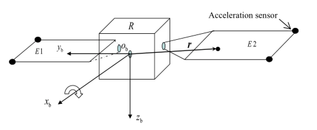
Fig.1 Sketch map of the spacecraft structure

whereξ1andξ2arethedampingratioofthetwosolararrays,respectively.
Defining a generalized coordinate vector as X=,Eq.(3)can be rewritten as follows

where I is a unit matrix.In the matrix form,one has

where

Considering the output equation,the state space equation of the system is written as

It should be mentioned here that this section presents the dynamic equation of the spacecraft.The aim of this dynamic model is to provide the output data of the system that will be used in the identification simulation.
3 Stochastic state-space model
This section presents the stochastic state-space model of the spacecraft.Considering the process and measurement noises of the system,and discretizing Eq.(6),one gets

wherexisthe2n×1statevector;uisthed×1inputvector;y sthel×1outputvector.ThematricesA,B,C,andDaresysemmatrix,inputmatrix,outputmatrix,andinfluencematrix,espectively.w∈R2n×1is the process noise,typically due o disturbances and modeling inaccuracies;v∈Rl×1is the measurement noise,typically due to the sensor inaccuracy. he noise vectors are assumed to be zero mean samples of a white noise process and with covariance matrices[15]

where E is the expected value operator and δpqis the Kronecker delta.
The above Eq.(7)is one of several models traditionally employed for linear identification problems since measurementsoftheinputaretypicallyavailable.However,ofspecial interest in this paper is the case where structural response measurements are available,but no input measurements are available.As a consequence,a more appropriate approach to the modeling of structural systems subjected to environmental loads is the stochastic state-space model

Using this model,it is clear that no differentiation is made between theinput uandtheprocessandmeasurement noises so that the terms Bu(k)and Du(k)are now modeled by the quantities w(k)and v(k).
Since w(k)and v(k)are zero-mean samples of a whitenoise process,the following expressions can be achieved

The covariance matrix of the state vector isThe covariance matrix of the state vector and the output vector is
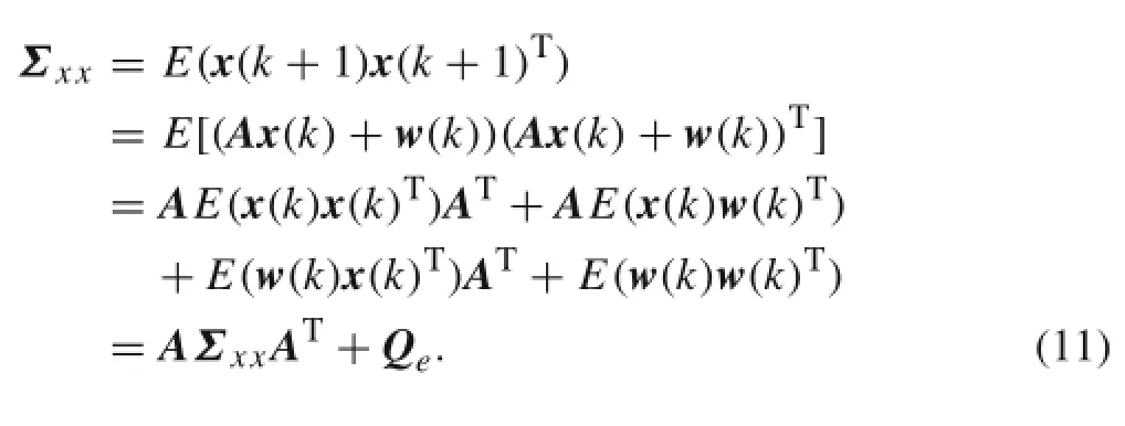

The covariance matrix of the output vector is

By the recurrence for the equation x(k+1)=Ax(k)+w(k),one can derive

Thus,the covariance matrix of y(k+i)and y(k)isEquations(12),(13),and(15)formabasisformanystochastic system identification schemes,including that of the SSI method presented in the next section.

4 Covariance-driven stochastic subspace identification
The covariance-driven stochastic subspace identification algorithm[16-19]uses direct estimates of the covariance of the response to identify the system.In the SSI-COV algorithm,the Hankel matrix is constructed using the output data firstly,then the block Toeplitz matrix is formulated that consistsofcovariances,finallythesingularvaluedecomposition(SVD)method is adopted to obtain the system matrix and the modal parameters are work out based the system matrix. The detailed process is discussed below.
4.1 Stochastic subspace identification algorithm
The output measurements are gathered in a block Hankel matrix with 2i block rows and N columns.For statistical reasons,it is assumed that N→∞.The Hankel matrix can be divided into a past part and a future part

The covariance matrix of the output data is defined as

where the s?econd equation follows from the ergodicity assumption[19].Of course,in reality,a finite number N of dataisavailableandacovarianceestimateissimplyobtained by dropping the limit in Eq.(?17).
Hereto,a block Toeplitz matrix T1|i∈Rli×liis formed that consists of covariances

Referring to Eq.(15),one has Λi=CAi-1G,so the block Toeplitz matrix T1|ican be rewritten as
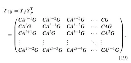
or
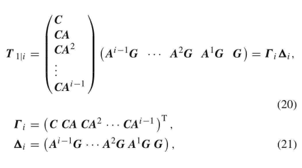
where Γiis the extended observability matrix and Δiis the reversed extended stochastic controllability matrix.
TheSVDdecompositionoftheblockToeplitzmatrixT1liwill then result in the following

where U and V are both orthogonal matrices andis a diagonal matrix.
Comparing Eq.(20)with Eq.(22),one obtains

where W is a non-singular matrix.Multiplying with W is regardedasanequivalenttransformationoftheoriginalstatespacemodel.Here,W isreplacedbyaunitmatrix.Therefore,Eq.(24)can be rewritten as follows

Based on Eqs.(19)-(21),the block matrix T2|i+1can be defined as
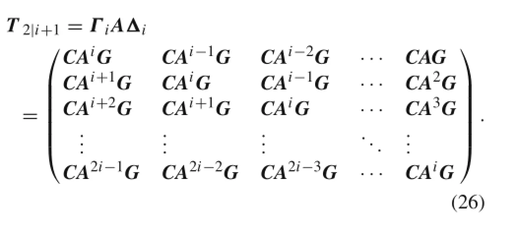
According to Eq.(18),T2|i+1can be calculated as the following form
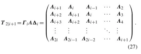
Substituting Eq.(25)into Eq.(27),one obtains

With the matrix A determined,the identification of modal parametersstartswitheigenvaluedecompositionoftheidentified system matrix A


where Δt is the data sampling period.
Note that these eigenvalues occur in conjugated pairs and can be written as

whereωiisthenaturalfrequencyandξiisthedampingratio. Then the natural frequency ωiis obtained as

where Re(λci)and Im(λci)are the real part and imaginary part of λci,respectively.

Fig.2 Schematic of the augmented stochastic system

Fig.3 The three degree of freedom(3-DOF)system
4.2 Stationary non-white excitation
Considering the original stochastic state-space model under stationary non-white excitation

Input vector˜u(k)possessing spectra that are not flat across the observation bandwidth,can be modeled as outputs of linear time invariant(LTI)dynamic systems referred to as shaping filters[20].In state-space,these filters have the following form

where uf(k)is a sample vector from a white noise process,Afis the system matrix for the filter,Cfis the observation matrix,Dfis the direct feed-through matrix,xf(k)is the filterstate,Bfisthenoiseinputmatrix,andtheresponse˜u(k)is the filtered input to the stochastic system.The dynamic characteristicsofthissystem,containedintheeigenstructure of Af,determine the spectral characteristics of this input process.It is assumed that the eigenvalues of Afdiffer from those of A.
Anaugmentedversionofthestochasticstate-spacemodel,to accommodate the shaping filter dynamics,is thus possible using the following definitions

which results in the augmented system

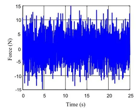
Fig.4 Time history curve of white noise
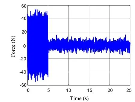
Fig.5 Time history curve of stationary non-white
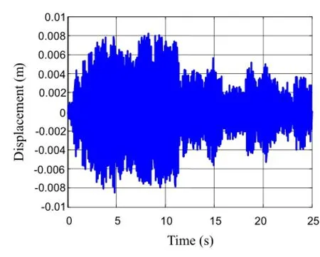
Fig.6 Time history of displacement
Considering the derivation in Sect.3,the above equations can be rewritten as


Fig.7 Fast fourier transform algorithm (FFT)of displacement response

Fig.8 Time history of displacement
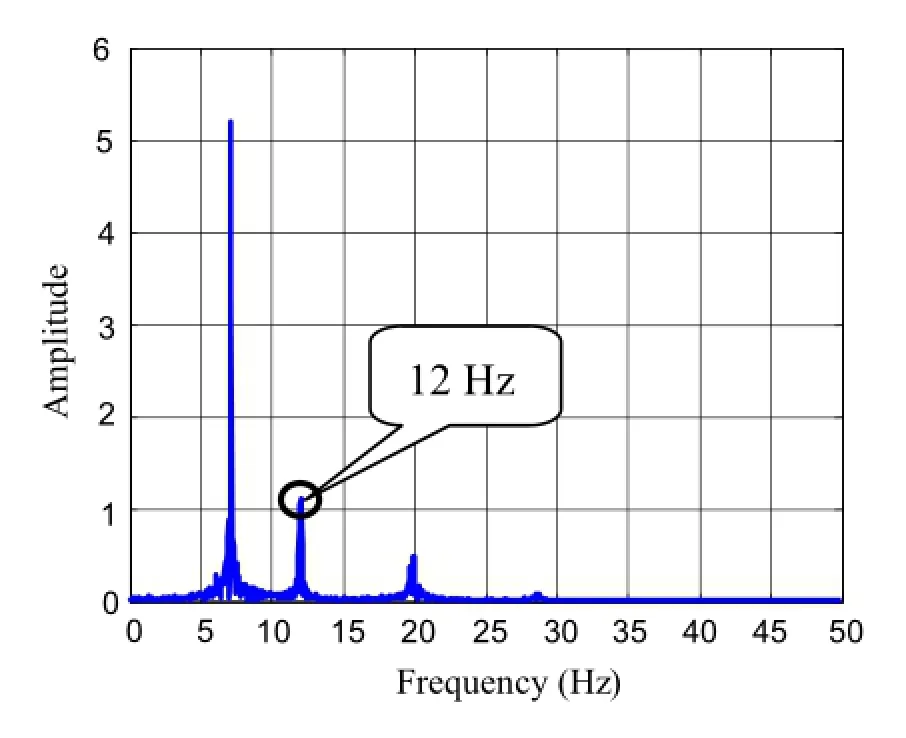
Fig.9 FFT of displacement response
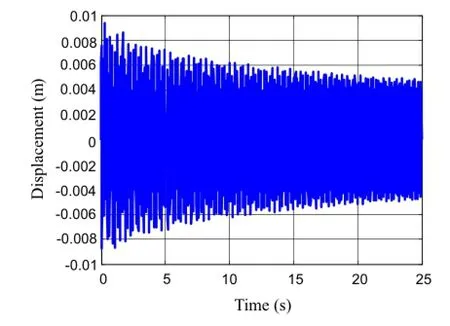
Fig.10 Time history of displacement
This is a new stochastic system,which is under white noise excitation.The process noise w(k)and measurement noise
v(k)are unaffected by the augmentation.A block diagram illustrating the shaping filter operation is shown in Fig.2.
The eigenvalue λarand eigenvector
for the rthmode of Aaare computed from the characteristic polynomial|λaI-Aa|=0,for which the related eigenvalues problem is as follows

Noteherethatthedistinctionbetweentheeigenvaluesof AfandA(i.e.,λp/=λfq∀p,q),isnecessary.Foraneigenvalue λrassociatedwiththeoriginalstochasticsystem,thequantity(λarI-Af)in Eq.(38)cannot equal zero.Therefore,in this case Eq.(38)can only be satisfied if φfr=0.Equation(37)then reduces towhich is simply equal to the result for the white noise excitation case.


Table 1 Identification results of 3-DOF system(Hz)
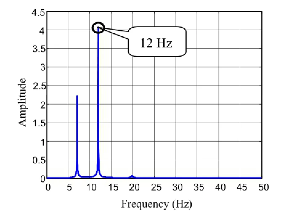
Fig.11 FFT of displacement response
Forstationarynon-whiteexcitation,theoriginalstochastic system may be modified to include the shaping filter subsystem producing an augmented system model driven by white noise inputs.The effect of colouration of the excitation is that eigenvalues associated with the input process appear in the augmented system matrix.This result is applied to both discrete and continuous-time model.
5 Numerical simulations
SincethetheoreticalbasisoftheSSImethodwasdiscussedin the above sections,two simulation examples are performed in this section to prove the effectiveness of the algorithm proposed in this paper.
5.1 The identification of a 3-DOF system
As an example illustrating the identification method of this paper,consider the three degrees of freedom(3-DOF)sys-tem illustrated in Fig.3.The physical parameters of the system are m1=m2=m2=1 kg and k1=k2= k2=10000 N/m;the three natural frequencies are 7.0831,19.8462,and 28.6787Hz,respectively.In the simulation,three types of external excitation,including white noise,stationary non-white,and sine,are considered the system input,respectively.The excitations are put on the third mass. The time histories of white-noise and stationary non-white are displayed in Figs.4 and 5,respectively.For the stationary non-white excitation,the input is combined with sine and white noise,where the sine part is chosen to be sin(2π fe×t)which lasts for 5s.For the sine excitation,the input signal is set to be sin(2π fe×t)and its time history is omitted.Output measurements are collected from the first mass.In the simulation,the sample frequency is chosen to be 100Hz and the parameter feis set to be 12Hz.
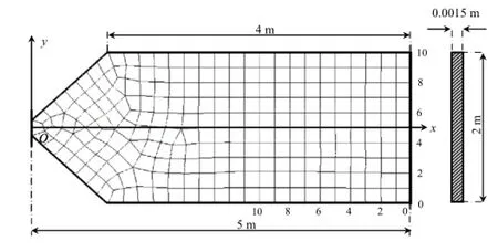
Fig.12 Solar array with FEM girding
The mass matrix,stiffness matrix,and damping matrix in dynamical equation for 3-DOF system are


Table 2 Physical parameters of the solar array
Under the white noise excitation,Fig.6 illustrates the displacement response of the first mass and Fig.7 is the corresponding fast fourier transform algorithm(FFT)result.As the output of the system is obtained,the SSI-COV methodmay be used to identify the modal parameters.The identified results are presented in the second column of Table 1.It is observed that the identification results are very close to the theoretical ones,which proves the validity of the method in this paper.
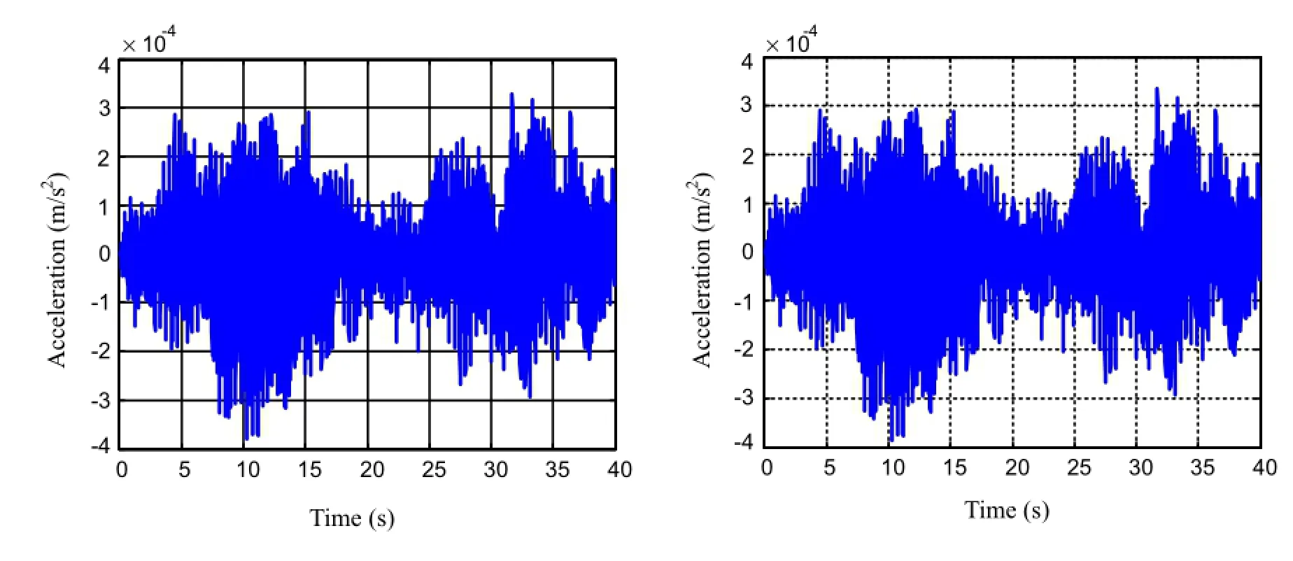
Fig.14 Outputs of two sensors on the solar array E1
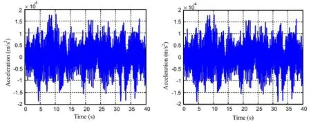
Fig.15 Outputs of two sensors on the solar array E2
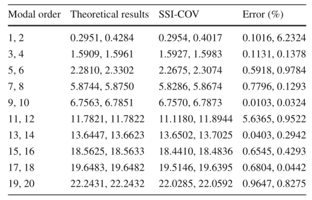
Table 3 Identification results of the spacecraft(Hz)
When stationary non-white and sine excitations are used forthesystem,theresultsaregiveninFigs.8-11,andthethird and fourth columns of Table 1.It is observed from Table 1 that the colouration of the input process does not affect the identification of the stochastic system;the identification results are almost identical to the theoretical ones.In Figs.9 and 11,a peak at 12Hz indicates that the frequency associated with the input signal appears in the response of system,and this frequency is identified by the SSI-COV method as shown in the second row of Table 1.
5.2 Identification of spacecraft
Here the SSI-COV method is applied to identify the modal parameters of the spacecraft shown in Fig.1.The geometric sketch of the solar array is shown in Fig.12.It is assumed that two acceleration sensors are used for each solar array,so there are in total four sensors for the spacecraft system. The optimal positions of the sensors can be determined by using the particle swarm optimization(PSO)and are shownas the black spots in Fig.1.These positions are the same as those for the engineering test satellite VI(ETS-VI)given in Ref.[6].The measurement signal of these four sensors will beusedasthesystemoutput.Inthesimulation,awhitenoise process will be used as the system input.The excitation is the torque and is put in the xbdirection of the spacecraft,as showninFig.1.Thetimehistoryofexcitationisdisplayedin Fig.13.The physical parameters of the two solar arrays are listed in Table 2.The moment inertia of the system is given by J=.The data sampling frequency is chosen as 100Hz.
Underthewhitenoisetorque,theoutputsofthefouraccelerationsensorsareshowninFigs.14and15.Sincetheoutput data of the system is known,the SSI-COV method may be used to identify the natural frequencies of the system and the results are displayed in the third column of Table 3.The first 20 frequencies of the system are presented in Table 3. Forcomparison,thetheoreticalresultsofnaturalfrequencies calculatedbasedonEq.(5)aregiveninthesecondcolumnof Table 3.Since the spacecraft is symmetrical,the natural frequencies of the system are in pairs.It can be observed from Table 3 that the results of identification are very close to the theoretical ones,which proves the validity of the method in this paper.
Fromtheabovesimulationresults,wedrawtheconclusion that the modal parameters of the spacecraft are effectively identified by the SSI-COV method as long as the output data of the system under ambient excitation is known.For space structures,itisofteninfeasibletomeasureexternalexcitation such as environmental load.In this case,it would be very convenient to adopt the method presented in this paper to complete on-orbit identification of the system.
6 Conclusion
Inthispaper,dynamicmodelingandparameteridentification of spacecraft are studied.The Lagrange method is adopted toestablishthedynamicequationofthesystem,andtheSSICOVmethodisusedforparameteridentification.Acomplete technical analysis process of parameter identification is presented in detail.The advantage of this identification method is to use only the outputs of the system under ambient excitation to identify modal parameters of the system;therefore,it has good practical engineering value.Simulation results prove the validity of this identification method.
Acknowledgments TheprojectwassupportedbytheNationalNatural ScienceFoundationofChina(Grants11132001,11272202,11472171),the Key Scientific Project of Shanghai Municipal Education Commission(Grant 14ZZ021),the Natural Science Foundation of Shanghai(Grant 14ZR1421000),and the Special Fund for Talent Development of Minhang District of Shanghai.
References
1.Song,X.J.,Yue,B.Z.,Wu,W.J.:Investigation on attitude disturbance control and vibration suppression for fuel-filled flexible spacecraft.Acta Mech.Sin.31,581-588(2015)
2.Tobin,A.,Greg,A.:On-orbit modal identification of the Hubble space telescope.In:Proceeding of the American Control Conference,Seattle,WA,402-406(1995)
3.Mohamed,K.,Scot,M.N.,Sydney,H.,etal.:Shuttle-ISSFlight-7A onOrbitTestVerification:PreandPostFlightAnalysis.Societyfor Experimental Mechanics,The Boeing Company,Seattle(2003)
4.Mohamed,K.,Sydney,H.,Theodore,B.,et al.:Modal Analysis and Correlation of International Space Station 4A Mated Configuration.SocietyforExperimentalMechanics,TheBoeingCompany,Seattle(2002)
5.Yamaguchi,I.,Kida,T.:ETS-VI on-orbit system identification experiments.JSME Int.J.40,623-629(1997)
6.Shuichi,A.,Yamaguchi,I.:On-orbit system identification experiments on Engineering Test Satellite-VI.Control Eng.Pract.7,831-841(1999)
7.Yamaguchi,I.,Kida,T.,Kasai,T.:Experimental demonstration of LSSsystemidentificationbyeigensystemrealizationalgorithm.In: Proceedings of American Control Conference,Seattle,WA,407-411(1995)
8.Ishikawa,S.,Yamada,K.,Yamaguchi,I.,et al.:ETS-VI on-orbit parameter estimation by random excitation.In:Proceedings of Astrodynamics Symposium,Halifax(1995)
9.Kasai,T.,Komatsu,K.,Sano,M.:Modal parameter identification of controlled flexible structures.AIAA J.Guidance Control Dyn. 20,184-186(1997)
10.Kim,H.M.,Bokhour,E.B.:Mir structural dynamics experiment:a flight experiment development.In:Proceedings of the 38th AIAA SDM Conference,Kissimmee,FL,577-585(1997)
11.Kim,H.M.,Kaouk,M.:Mir structural dynamics experiment:first phase test and data analysis.In:Proceedings of the 39th AIAA SDM Conference,Long Beach,CA,204-212(1998)
12.Kim,H.M.,Kaouk,M.:Mir structural dynamics experiment:first test and model refinement.In:Proceedings of the 40th SDM Conference,St.Louis,MO(1999)
13.Kim,H.M.,Kaouk,M.:Modal analysis and model correlation of the Mir Space Station.In:Proceedings of the 18th IMAC Conference on Computational Challenges in Structural Dynamics,San Antonio,Texas,1724-1730(2000)
14.Paweł,O.,Jan,A.,Michał,N.:Solution of the Kalman filtering problem in control and modeling of a double inverted pendulum with rolling friction.Meas.Autom.Robot.1,63-70(1980)
15.Edwin,R.,Guido,R.:Reference-based combined deterministicstochasticsubspaceidentificationforexperimentalandoperational modal analysis.Mech.Syst.Signal Process.22,617-637(2008)
16.Antonio,V.,Andrew,R.:Output-only cyclo-stationary linearparameter time-varying stochastic subspace identification method for rotating machinery and spinning structures.J.Sound Vib.337,45-70(2015)
17.Zhang,G.W.,Tang,B.P.,Tang,G.W.:An improved stochasticsubspace identification for operational modal analysis.Measurement 5,1246-1256(2012)
18.Michael,D.,Laurent,M.:Efficient multi-order uncertainty computation for stochastic subspace identification.Mech.Syst.Signal Process.38,346-366(2013)
19.Bart,P.,Guido,R.:Stochasticsystem identificationfor operational modalanalysis:areview.J.Dyn.Syst.Meas.Control123,659-667(2001)
20.Pridham,B.:State space modeling and identification of stochastic linear structural systems.[Ph.D.Thesis],McMaster University,Canada(2004)
16 July 2015/Revised:15 March 2016/Accepted:27 April 2016/Published online:20 June 2016
✉ Guo-Ping Cai caigp@sjtu.edu.cn
1Department of Engineering Mechanics,State Key Laboratory of Ocean Engineering,Shanghai Jiao Tong University,Shanghai 200240,China
- Acta Mechanica Sinica的其它文章
- Erratum to:Control of surface wettability via strain engineering
- Optimal design of near-Earth asteroid sample-return trajectories in the Sun-Earth-Moon system
- Vibration analysis of hard-coated composite beam considering the strain dependent characteristic of coating material
- New method for oblique impact dynamics research of a flexible beam with large overall motion considering impact friction force
- The comparative analysis of rocks’resistance to forward-slanting disc cutters and traditionally installed disc cutters
- Analytical and finite-element study of optimal strain distribution in various beam shapes for energy harvesting applications

