Optimal design of nanofiltration system for surface water treatment☆
Fei Bi,Haiyang Zhao ,Zhijun Zhou ,Lin Zhang ,*,Huanlin Chen ,Congjie Gao ,3
1 Key Laboratory of Biomass Chemical Engineering of MOE,College of Chemical and Biological Engineering,Zhejiang University,Hangzhou 310027,China
2 96657 Unit of the Armed Forces,Beijing 100011,China
3 Ocean College,Zhejiang University of Technology,Hangzhou 310014,China
1.Introduction
Membrane-based processes,such as reverse osmosis(RO)and nanofiltration(NF),seem to be one of the most promising strategies for water treatment to relieve the urgency of water shortages worldwide[1,2].Previous researches suggested that the NF process is more suitable for surface water treatment than the RO process because it can guarantee the retention of trace minerals and requires lower energy consumption[3–6].
Salt rejection,water yield,water recovery,and energy efficiency are the most important indexes to evaluate the performance and reason ability of the membrane systems in the process design.These indexes have a close relationship with the operation parameters and the membrane element arrangement.On the one hand,the operation parameters can affect system performance by changing the concentration polarization,which may worsen the membrane flux and salt rejection and intensify the membrane fouling if the upper boundary is reached(Table S1)[7,8].On the other hand,the element arrangement also has a significant impact on the performance of the membrane system;for example,the cascade arrangement provides a higher water recovery while the parallel arrangement can support a larger water yield[9,10].
Currently,design ideas for the NF process mainly follow the service experience of the RO system.However,the separation mechanism of NF membranes differs from that of RO membranes[11],which results in a big difference in the salt rejection between NF and RO membranes[12].Furthermore,this difference can cause a distinction between NF and RO systems.The salt rejection of the NF system is quite different from that of an NF element because the salt rejection of the NF element is far from satisfactory and is sensitive to the ion concentration,ion types,and ion charges in the feed solution[13],while the salt rejection of the RO system is quite close to that of a single RO element owing to its almost total rejection of all ions.Therefore,the design of an NF system cannot totally depend on experience of RO systems due to the difference in the separation performance between NF and RO membranes.In our previous work[14],the maximum water recovery in the NF system was found to be quite different from that in the RO system.If the performance relationship between the NF system and a single NF element can be clarified,it will be helpful for the element screen and the element arrangement in real applications.
In this work,the effect of operation parameters,such as water flow(Qf),operation pressure(P),and ratio of concentrate flow(Qc)to permeate flow(Qp),on the membrane performance will be discussed firstly.Then,based on the stable salt rejection(ro)and maximum water recovery(Rmax)of the NF system,the optimal design of the element arrangement in the NF system will be investigated in detail.
2.Theoretical Background
In the steady state of a membrane system,there is mass balance Eq.(1)and mass conservation Eq.(2):


whereQf,Qp,andQcdenote the flows of feed water,permeate water,and concentrate water,respectively,andCf,Cp,andCcdenote the salt concentrations in feed water,permeate water,and concentrate water,respectively.
Water recovery(R),the observed rejection(ro),and permeation flux(Jw)are described as Eqs.(3),(4),and(5),respectively:
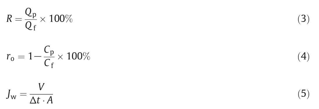
whereV,A,and Δtare the volume of permeated water,the membrane area,and the permeation time,respectively.
In the RO system,the concentration polarization degree(CPD)is usually used to characterize the dynamic state near to the membrane surface,and is defined as:

whereCmis the solute concentration near the membrane surface.CPD is difficult to measure in real experiments but can be calculated by available physical models[15].
3.Experimental
3.1.Materials
Spiral NF membrane(NF1-2540 type,see Supporting Information)was purchased from Vontron,Beijing.Hollow fiber polysulfone(PSF)ultra filtration(UF)membrane was used at pretreatment with a molecular weight cutoff(MWCO)of 45000 and pure water yield of 2.0–3.5 m3·h-1.Sodium chloride and magnesium chloride(analytical grade)were purchased from Sinopharm Chemical Reagent Co.,China.
3.2.Performance test of NF membrane for the simulated salty water
Membrane performance was tested in a cross flow system similar to ourprevious work[14].The aqueous saltsolution was prepared as listed in Table 1 and used in the performance test in different conditions.The flow can be directly read from the flow gauge,and the salt rejection(namely observed rejection,ro)can be calculated by Eq.(4)[16].All data were collected at least in triplicate,and the results were averaged.

Table 1Range of salt concentrations and test parameters
3.3.Performance test of NF membrane for the real surface water
Surface water was taken from the Qiantang River(Hangzhou,China),which is a freshwater river from inland to the East China Sea.The original water was filtrated by the sand leach and UF membrane in sequence and then went into the NF membrane module.In this work,the natural organic matters(NOMs)is characterized as UV254 and total organic carbon(TOC)[17].UV254 was measured by using a visible light-ultraviolet spectrophotometer(Spectrumlab 54,Lengguang Tech,China).TOC was measured by Liqui TOCII(Elementar Analysensystine,Germany).
3.4.Performance calculation of RO membrane by Simulation software
Simulation software(IMS design 2010,provided by Hydranautics)was used to simulate the separation performance of the RO membrane in the saltsolution(200 mg·L-1)[18].ESPA2–8040 membrane was used to calculate the water recovery in the RO system with different element arrangements.The temperature and pH were set at 25°C and 7,respectively.By regulating the feed flow and permeate flow,the RO system was equilibrated with a maximum CPD of1.2,and then the water recovery was recorded as the maximum recovery(Rmax).In all the tests,at least five readings were recorded and the averaged results plotted.
4.Results and Discussion
4.1.Effect of concentrate fl ow,pressure,and Q c/Q p on the observed rejection
In a single NF element,the observed rejection(ro)is usually affected by the operation pressure(P),concentrate flow(Qc),and the ratio ofQctoQp(Qc/Qp).Performance tests of the NF element in NaCl and MgSO4solutions under the same pressure showed that the observed rejection(ro)had a close relationship with the concentrate flow(Qc):the observed rejection(ro)of the NF element obviously improved when the concentrate flow(Qc)increased from 0 to 5 L·min-1and reached a plateau once the concentrate flow(Qc)was bigger than 5 L·min-1(Fig.1A and C).This is because as concentrate flow(Qc)increased,the permeate flow(Qp)decreased and the CPD became smaller.As a result,the observed rejection(ro)became higher.When the concentrate flow(Qc)became greater than 5 L·min-1(the cross- flow velocity and Reynolds number are 0.354 m·s-1and 7030.7,respectively),the concentration polarization almost disappeared and the observed rejection(ro)was close to the real rejection.However,an experimental test under different pressures suggested that the observed rejection(ro)may be barely affected by the pressure(P).It should be noted that the observed rejection(ro)was zero when the concentrate flow(Qc)was reduced,which means that the NF membrane was tested by dead-end rather than cross- flow filtration.In the dead-end filtration,the observed rejection(ro)of the NF membrane decreased rapidly and soon became zero.
On the other hand,by regulating the feed flow(Qf)and operation pressure(P),the NF system can maintain a constant concentrate flow(Qc).The results showed that the observed rejection(ro)was independent ofQc/Qpand showed a very small improvement as the concentrate flow(Qc)was increased from 5 to 7 L·min-1(Fig.1B and D).This may be due to the fact that the CPD became insensitive toQc/Qponce the concentrate flow(Qc)exceeded 5 L·min-1.Here it can be concluded that the observed rejection(ro)was mainly affected by the concentrate flow(Qc)and approached a plateau after the concentrate flow(Qc)exceeded 5 L·min-1.This finding is very useful to simplify the process design of the NF system in real applications.
Finally,observed rejections(ro)in the salt solution mixture showed a similar relationship with concentrate flow(Qc),operation pressure(P),and Qc/Qpcompared with the single salt solution(Fig.1E and F).It was found that observed rejection(ro)in the mixed solution was quite close to that in NaCl solution and different from that in MgSO4solution(Fig.S1),which indicated that the observed rejection(ro)in the mixed solution was mainly affected by the existence of the monovalent salt,namely NaCl.Therefore,in NF system design,the system rejection should be referred to the element rejection of monovalent salts if they exist.
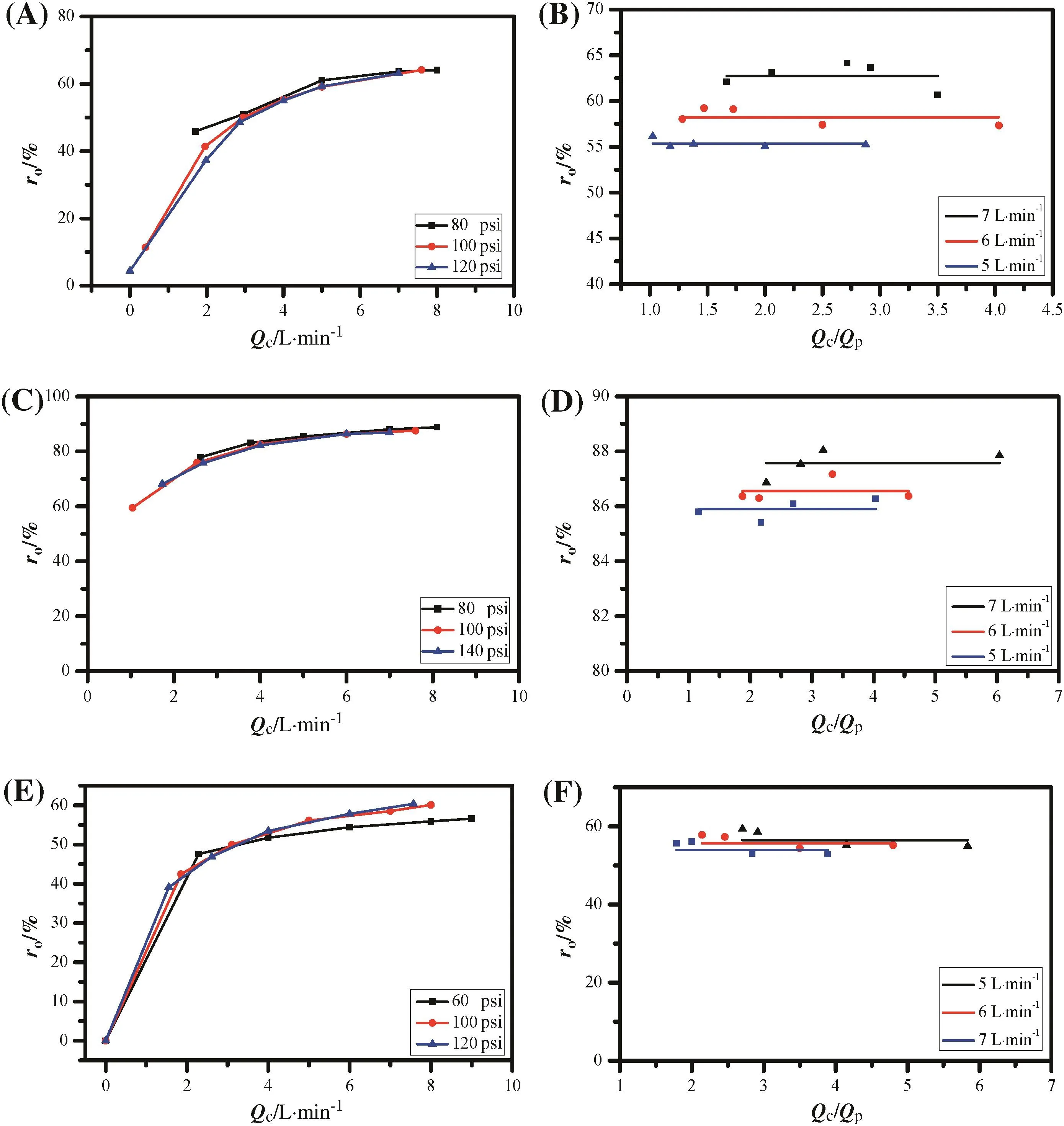
Fig.1.Effect of concentrate flow(A,C,and E)and Q c/Q p(B,D,and F)on the observed rejection in NaCl solution(A),(B);MgSO4 solution(C),(D);and mixed solution(E),(F),respectively(1 psi=6894.76 Pa).
The permeate water from the UF system was used as the feed in the NF system in this work.The effect of the concentrate flow(Qc)on the observed rejection(ro)of inorganic salt was similar to that in the above simulated system(Fig.2A),and the observed rejection(ro)was approximately 40%,which was lower than that in the single salt solution and can be attributed to the easy permeation of NO3-in the real water.The observed rejection(ro)became constant when the concentrate flow(Qc)was greater than 5 L·min-1.Additionally,the observed rejection(ro)of NOMs was also tested in the form of TOC and UV254 as shown in Fig.2B and presented a similar profile to that shown in Fig.2A.The observed rejection(ro)for organics became stable at around 50%when the concentrate flow(Qc)was greater than 5 L·min-1.
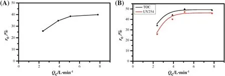
Fig.2.Effect of concentrate flow on the observed rejection of salt(A),UV254,and TOC(B)for real river water.
4.2.Effect of concentrate flow,pressure,and Qc/Qp on the permeation flux
The effects of concentrate flow(Qc),pressure(P),andQc/Qpon the permeation flux(Jw)have also been investigated,as shown in Fig.3.In all test solutions,by adjusting the flow(Qf)across the NF membrane and the operation pressure(P),it was found that the permeation flux(Jw)was barely changed under a specific pressure but increased slightly with decreases in concentrate flow(Figs.3A,C,and E).Although the concentrate flow(Qc)approached zero(dead-end filtration),the permeation flux(Jw)remained stable and did not vary with time.Since the concentrate flow(Qc)cannot affect the membrane flux(Jw),Qc/Qpis expected to have an irrelevant relationship with permeation flux(Jw).As shown in Figs.3B,D,and F,Qc/Qpshowed a negligible effect on the permeation flux(Jw)even thoughQc/Qpwas zero.
In an NF single element,as discussed above,salt rejection(ro)will become stable if concentration flow(Qc)is greater than 5 L·min-1while permeation flux(Jw)remains constant under certain pressure.Additionally,the observed rejection(ro)in the mixed solution was mainly determined by the monovalent salt.In a large NF system(several membrane elements),the water recovery and membrane arrangement should be adjusted to guarantee stable rejection(ro)and flux(Jw)in each element.The maximum water recovery(Rmax)in the NF system has been analyzed systematically in our previous work[14],and the optimal membrane arrangement will be discussed as follows.
4.3.Optimal arrangement of membrane elements in NF system
In the RO system,the element arrangement was mainly determined by the water recovery(R)in the RO system and number of elements in each module[9,10].To avoid a high concentration polarization near the membrane surface,the water recovery(R)for each RO element should not be greater than 15%.The water recovery(R)for an RO system with different elements can be estimated by the simulation software[18].According to our previous report[14],the water recovery(R)for the NF element can exceed 25%with a ratio ofQc/Qpof 3:1 to maintain stable salt rejection(CPD<1.2).In the NF system,as mentioned above,the concentrate flow(Qc)should be greater than 5 L·min-1to support stable salt rejection for each element.By calculating the concentrate flow(Qc)from the last element of the NF system with a Qc/Qpratio of 3:1,the water recovery(R)for the NF system with different elements can also be estimated(Supporting Information).Since the observed rejection(ro)was mainly determined by the monovalent salt,NaCl solution was used as the representative substitute for CPD calculation.The comparison of the maximum water recovery values(Rmax)for the NF and RO systems with different elements is shown in Table 2.
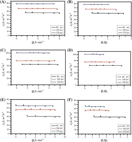
Fig.3.Effect of concentrate flow(A,C,and E)and Q c/Q p(B,D,and F)on the permeation flux in NaCl solution(A),(B);MgSO4 solution(C),(D);and mixed solution(E),(F),respectively(1 psi=6894.76 Pa).
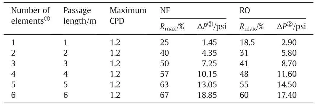
Table 2Comparison of maximum water recovery values in one-stage NF and RO systems
Obviously,the water recovery(R)in the NF system is higher than that in the RO system with fixed path length.The water recoveries(R)in the NF system with path lengths of 2,3,and 4 m are close to those in the RO system with path lengths of 3,4,and 5 m,respectively.This means that the NF system can support a higher water recovery(R)than the RO system with the same length of water passageway.
Generally,water recovery(R)in membrane systems should be higher than 75%when used in the treatment of river water with low salinity(100–500 mg·L-1),which requires RO and NF systems to have more than six elements.For the same water recovery,the NF system needs a shorter passageway length than the RO system,which leads to big differences in the pressure consumption and the system design between the RO and NF systems.
Taking the simple element arrangement of one stage as an example,the feed pressures(P)in the NF and RO systems with six elements are 280 kPa and 640 kPa,respectively.These two systems have a similar pressure drop(ΔP)due to the production of the permeate water.This pressure drop(ΔP)accounts for less than 20.3%of the pressure in the RO system but more than 42.9%in the NF system.This indicates that NF will waste more energy if the NF system is designed directly based on the design principal of the RO system,which is not reasonable.
The difference in the separation mechanism between the NF and RO membranes results in different constraint conditions in the design of these two systems.This means that the design of the NF system can refer to that of RO system but cannot be totally derived from the experience of the RO system.
In the design of the RO system,there are two general important rules that should be noted and adapted to the design of the NF system[9,10]:one is that the membrane elements should be arranged in wedge shaped style(Fig.S3)and the other is that the number of the elements should be the same in each vessel.In a two-stage process,the arrangement of 2/5+1/6 can also meet the recovery requirement of 80%,but the designer usually chooses to use the arrangement of 2/6+1/6.In the three-stage process,element arrangements of 3/4+2/5+1/5,5/3+2/4+1/5,and 5/3+2/4+1/4 can support a water recovery(R)of 85%as well,while the arrangement of 3/5+2/5+1/5 was considered the best.According to the general design rules described above,the element arrangements in the RO and NF systems with high water recovery values are listed in Table 3.
When the target recovery is lower than 80%,a two-stage arrangement is enough for both systems in spite of the difference in the number of elements and passageway length.However,the RO system needs a three-stage arrangement to meet the higher recovery requirement(≥85%),which is still within the capacity of the NF system with a two stage arrangement.Obviously,if the design of the NF system entirely follows that of the RO system,the NF system will be more complicated and will waste lots of assembly parts.

Table 3Comparison of element arrangements in NF and RO syste ms
5.Conclusions
Salt rejection of NF membrane is quite different from that of RO membrane,which leads to a big difference between the performance of the NF and RO systems.In our previous report,the maximum water recovery(Rmax)in the NF system was found to be quite different from that in the RO system.In this work,the separation performances and optimal arrangement of the NF system have been investigated.The observed rejection(ro)of the NF membrane was hardly affected by the pressure but was greatly affected by the concentrate flow(Qc).When the concentrate flow(Qc)was greater than 5 L·min-1,the observed rejection(ro)became nearly constant.At the same time,the membrane flux of the NF element is quite stable regardless of the water flow across the membrane surface.These findings are useful to guide the process design of the NF system.The two-stage arrangement is sufficient for the NF system to reach a water recovery of more than 85%,but a three-stage arrangement is required for the RO system to reach the same water recovery.
Nomenclature
A effective area of membrane,m2
Ccsalt concentrations in concentrate water,mg·L-1
Cfsalt concentrations in feed water,mg·L-1
Cmsolute concentration near the membrane surface,mg·L-1
Cpsalt concentrations in permeate water,mg·L-1
Jwpermeation flux,L·m-2·h-1
Poperation pressure,Pa
Qcconcentrate flow,L·min-1
Qc/Qpratio ofQctoQp
Qffeed flow,L·min-1
Qppermeate flow,L·min-1
Rwater recovery,%
Rmaxmaximum water recovery,%
roobserved rejection,%
Vvolume of permeated water,L
Ywater yield,%
ΔPpressure drop,Pa
Δtpermeation time,h
Supplementary Material
Supplementary data to this article can be found online at http://dx.doi.org/10.1016/j.cjche.2016.05.012.
[1]M.A.Shannon,P.W.Bohn,M.Elimelech,J.G.Georgiadis,B.J.Marinas,A.M.Mayes,Science and technology for water purification in the coming decades,Nature452(2008)301–310.
[2]A.Pérez-González,A.M.Urtiaga,R.Ortiz,I.Ibáñez,State of the art and review on the treatment technologies of water reverse osmosis concentrates,Water Res.46(2012)267–283.
[3]A.de la Rubia,M.Rodrigues,V.M.Leon,D.Prats,Removal of natural organic matter and THM formation potential by ultra-and nanofiltration of surface water,Water Res.42(2008)714–722.
[4]A.Orecki,M.Tomaszewska,K.Karakulski,A.W.Morawski,Surface water treatment by the nanofiltration method,Desalination162(2004)47–54.
[5]M.F.Abid,S.K.Al-Naseri,Q.F.Al-Sallehy,S.N.Abdulla,K.T.Rashid,Desalination of Iraqi surface water using nanofiltration membranes,Desalin.Water Treat.29(2011)174–180.
[6]J.R.Petersen,Composite reverse osmosis and nanofiltration membranes,J.Membr.Sci.83(1993)81–150.
[7]J.W.Nam,J.Y.Park,J.H.Kim,S.Kwon,K.Chon,E.J.Lee,H.S.Kim,A.Jang,The evaluation on concentration polarization for effective monitoring of membrane fouling in seawater reverse osmosis membrane system,J.Ind.Eng.Chem.20(2014)2354–2358.
[8]M.S.H.Bader,Nanofiltration for oil- fields water injection operations:Analysis of concentration polarization,Desalination201(2006)106–113.
[9]Hydranautics Company,RO and NF membrane product and technology manual,2008.
[10]Dow Chemical Company,FLIMTECTM RO and NF membrane elements product and technology manual,2008.
[11]K.Doederer,M.J.Farre,M.Pidou,H.S.Weinberg,W.Gernjak,Rejection of disinfection by-products by RO and NF membranes:Influence of solute properties and operational parameters,J.Membr.Sci.467(2014)195–205.
[12]J.W.Wang,D.S.Dlamini,A.K.Mishra,M.T.M.Pendergast,M.C.Y.Wong,B.B.Mamba,V.Freger,A.R.D.Verliefde,E.M.V.Hoek,A critical review of transport through osmotic membranes,J.Membr.Sci.454(2014)516–537.
[13]J.Luo,Y.Wan,Effects of pH and salt on nanofiltration—A critical review,J.Membr.Sci.438(2013)18–28.
[14]F.Bi,H.Zhao,L.Zhang,Q.Ye,H.Chen,C.Gao,Discussion on calculation of maximum water recovery in nanofiltration system,Desalination332(2014)142–146.
[15]I.Sutzkover,D.Hasson,R.Semiat,Simple technique for measuring the concentration polarization level in a reverse osmosis system,Desalination131(2000)117–127.
[16]H.Zhao,S.Qiu,L.Wu,L.Zhang,H.Chen,C.Gao,Improving the performance of polyamide reverse osmosis membrane by incorporation of modified multi-walled carbon nanotubes,J.Membr.Sci.450(2014)249–256.
[17]A.Matilainen,E.T.Gjessing,T.Lahtinen,L.Hed,A.Bhatnagar,M.Sillanpää,An overview of the methods used in the characterisation of natural organic matter(NOM)in relation to drinking water treatment,Chemosphere83(2011)1431–1442.
[18]Hydranautics Company,RODESIGN help manual,2007.
 Chinese Journal of Chemical Engineering2016年12期
- Chinese Journal of Chemical Engineering的其它文章
- Statistical mechanics and artificial intelligence to model the thermodynamic properties of pure and mixture of ionic liquids☆
- Modification and sequential treatment of EU-1 zeolite in mild alkali and alkaline-acid conditions
- Catalytic kinetics of dimethyl ether one-step synthesis over CeO2–CaO–Pd/HZSM-5 catalyst in sulfur-containing syngas process☆
- Development of a bifurcation analysis approach based on gPROMS platform☆
- A comprehensive fractal char combustion model☆
- Molar volume of eutectic solvents as a function of molar composition and temperature☆
