Effect of the shaft eccentricity and rotational direction on the mixing characteristics in cylindrical tank reactors
Houari Ameur
Institute of Science and Technology,University Center Ahmed Salhi,Ctr Univ Naâma,45000,Algeria
1.Introduction
Mixing is widely used in several industrial processes and it is generally performed in stirred tanks.Baffling of the stirred tank is an effective strategy to enhance the scale mixing by breaking the primary vortex[1–3].However,there are processes where unbaffled tanks are preferred,as for mixing rheologically complex fluids[4]or in pharmaceutical and food industries where the cleaning is a great issue[5].
Mixing of highly shear thinning fluids results in the formation of pseudo-caverns in the impeller vicinity and stagnant or slow moving fluids elsewhere.It is recommended to eliminate the stagnant regions since their presence yields poor heat and mass transfer rates,and high temperature gradients.The mixing quality may be improved by the turbulence invoked by the increase of the impeller rotational speed.However,there are instances where high values of the impeller speed are not applied,especially for highly viscous non-Newtonian fluids such as encountered in food,paint,petroleum,polymer industries.For these fluids,the effective mixing is prohibited in the laminar regime,by the presence of Isolated Mixing Regions(IMR)[6,7].Therefore,strategies such as the shaft eccentricity have been introduced in order to reduce the mixing time[8,9],particularly for unbaffled vessels which are preferred in industrial processes because of the easiness of the cleaning operation inside the vessel[10,11].
Alvarez[12]discussed interesting aspects on the mixing by an eccentric impeller in the laminar regime.Ng and Ng[13]investigated the laminar mixing characteristics of Newtonian fluids in a cylindrical vessel stirred by a plate impeller.The radial mixing is found to be poor in an unbaffled vessel stirred by a concentric impeller;however,baffles enhance marginally the radial exchange between the vessel walls and inner fluid particles.This issue may be overcome by using the shaft eccentricity.
The eccentricity can provide a great enhancement in the axial circulation of fluid particles[14]and yields similar effects as the baffles,where the tangential fluid flows are impeded in both cases[9].The shaft eccentricity generates a vortex-shedding phenomenon from the flow–shaft interactions[10]and the flow instabilities caused by the upper vortex decrease with increasing impeller blade thickness or with increasing eccentricity ratio[16].
For an eccentrically located Rushton turbine,Galletti and Brunazzi[15]found that the lower vortex is inclined by 20°and the upper vortex is inclined by 15°justabove the impeller,and 8°near the free liquid surface.However,Montanteet al.[17]found an inclination by 10°for the lower vortex and 30°for the upper vortex,with respect to the vertical plane.These discrepancies are due to the difference in mixing system geometries,increasing the impeller clearance from the vessel base and its eccentricity leads to a widening inclination of the uppervortex,as reported by Galletti and Brunazzi[15].
For a propeller and a Newtonian fluid,Karczet al.[18]reported that the mixing time decreases as the shaft eccentricity increases,but with additional energy costs.Gogate and Pandit[19]showed that the experiment procedure affects the measurement of mixing times for eccentrically located impellers.Karczet al.[18]confirmed this finding for propeller of HE3 turbine and reported that the values of the measured mixing time depend on the measuring point inside the tank.
For multiple impeller systems,the eccentricity may cause a stronger compartmentalization effect,as reported by Woziwodzki and Jedrzejczak[20].Yanget al.[21]studied the mixing of two stratified miscible liquids in a vessel stirred by a four pitched-blade impeller.They reported that the eccentric location of the impeller is not suitable to blend the low-viscosity miscible liquids starting from a stratified state,especially when the values of the Richardson number(Ri)are low.However,this position may reduce the mixing time for higherRi[21–23].We note that the Reynolds numberReis proportional to impeller rotational speedN,and the Richardson numberRidecreases with increasingN.
Several types of eccentrically located impellers were investigated by some researchers,the Rushton turbine was studied by Montante et al.[17],HE3 impeller by Cudak and Karcz[24],propeller by Szoplik and Karcz[25,26],propeller and HE3 turbine by Karcz and Cudak[27],and Scaba 6SRGT impeller by Ameur et al.[28].The combinations of two eccentric impellers were studied by Ascanio and Tanguy[29]for singlephase,by Cabaret et al.[30]for two-phase gas–liquid systems with the Newtonian and non-Newtonian fluids.For Newtonian and two-stage impellers(Rushton turbine,six-pitched-blade turbine and six- flat blade turbine),Woziwodzkiet al.[31]were interested in the transitional regime and Woziwodzki and Jedrzejczak[20]studied the flows within the laminar regime.
Knowledge about the impact of the impeller eccentricity on the mixing characteristics for highly viscous non-Newtonian fluids is limited,especially for retreat-blade impellers.Therefore,in the present paper an attempt is made to explore the effect of eccentricity on the 3D fluid flows and power requirements for mixing shear thinning fluids by six-retreat-blade impellers.Effects of the rotational direction are also studied.
2.Mixing System
The mixing system under study(Fig.1a)is a cylindrical unbaffled tank with a flat bottom(diameterD=400 mm and heightH/D=1),equipped by an impeller having six-curved blades(diameterd/D=0.4,heighth/D=0.1 and curvaturebc/D=0.06)and placed at a clearance from the vessel base c/D=0.5.The ratio ds/D(diameter shaft)is set to 0.03.
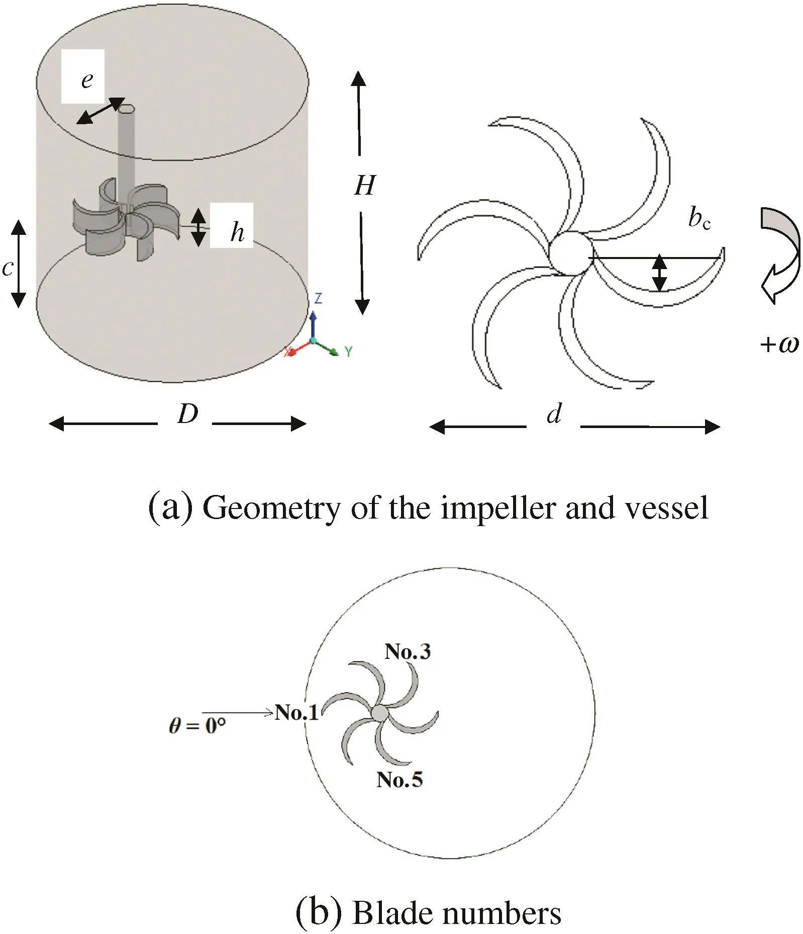
Fig.1.Mixing system.
The effect of impeller eccentricity is investigated by realizing three configurationse/D=0(i.e.concentric position),0.12 and 0.24.Each blade is given a number in order to ease the discussion of results(Fig.1b).The origin of the angular coordinate θ =0°is taken at the prolongation of blade No.1(Fig.1b).
3.Theoretical Background
Three fluids are used in this study;it concerns the emulsions named E1,E2 and E3 which are models of food emulsions.The rheological properties of the three fluids are summarized on Table 1,based on measurements achieved by Thakuret al.[32].

Table 1Rheological properties of the fluids simulated
The three solutions simulated have a shear thinning behavior modeled by the power-law(Oswald law).In this situation,the shear stress is related to the shear strain rate by the following equation:

wheremis the consistency factor.
The working fluid is modeled by the Ostwald–de Waele law,as:

The generalized Reynolds number for a shear thinning fluid(following the Ostwald model)is:

whereρis the density,N is the impeller rotational speed and ksis a weak function of the stirrer type and it is taken equal to 11.5.The power consumption is calculatedviathe following equation:

where Qvis the viscous dissipation.
The elementdvis written as:

In the dimensionless form,we define the power number as:

4.Numerical Method
The Reynolds number is changed from 0.1 to 1000,covering the laminar and transitional regimes.Based on several studies and confirmed by different authors[33–37].Pakzadet al.[38]reported that the macro-instabilities happening in the transitional flow regime close to the laminar regime can be neglected.Therefore,in the transitional regime,the lower part can be modeled as laminar and the upper part as turbulent.
In steady-state and for incompressible fluids,the three-dimensional fluid flows inside the vessel were predicted by solving the governing equations of mass and momentum conservation using ANSYS CFX.The mixing system geometry was created by ANSYS ICEM CFD and then divided into tetrahedral meshes(Fig.2).In order to capture details of the flow boundary layer,an advanced size function was utilized during the meshing operation near the walls of the mixing system.Since the impeller has curved blades,the mesh density around the impeller was increased to accurately capture the blade design.
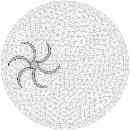
Fig.2.Tetrahedral meshes.
Grid in dependency was verified by comparing the converged results of power consumption and velocities around the impeller.During the refinement process,the size function is kept and the size of elements near the walls of the mixing system is reduced.With the computational mesh of about 1253897 elements,the obtained results of the selected variables(NpandVmax)did not change by more than 2%.Therefore,this was adopted for further simulations.
Since the tank is unbaffled,the stirrer rotation was modeled by using the Rotating Reference Frame(RRF)method.This technique was used by several authors for the same mixing system and satisfactory results were found[39,40].Further details are provided in our previous paper[41].
The second order upwind scheme was used for the convection terms.To perform pressure–velocity coupling,a pressure-correction method of the type Semi-Implicit Method for Pressure Linked Equations Consistent(SIMPLEC)is used.Solutions were converged when normalized residuals for pressure and velocity drop below 10-7.Most calculations required 1000–1500 iterations and about 4–5 h.
5.Results and Discussion
5.1.Validation
As a first step,it is necessary to check the reliability of the computer code and the numerical method performed.For this purpose,we referred to the experimental work of Vennekeret al.[42].With exactly the same geometry and the same fluid(shear thinning fluid,n=0.85)as those undertaken by these researchers,we predicted the variation of tangential velocity along the vessel radius(Fig.3).As remarked on this figure,the comparison shows a satisfactory agreement.
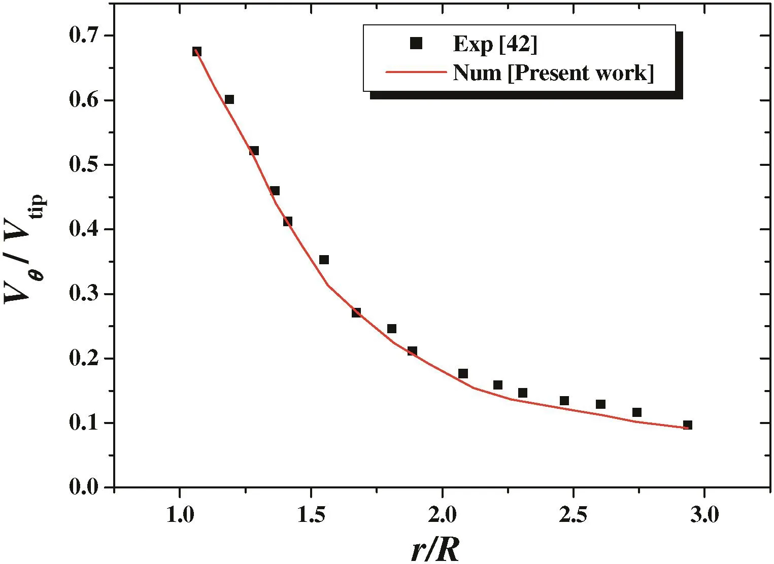
Fig.3.Tangential velocity along the vessel radius,n=0.85,Re g=22200.
5.2.Effect of the impeller eccentricity
Generally,the mixing systems are designed basing on the symmetric characteristics due to the easiness of implementation.However,when the fluid flow is laminar,a strong degradation of the mixture quality is observed due to the presence of isolated mixing regions caused by the symmetric conditions[13].Alvarez et al.[14]reported that the drop in mixing performance is due to the structure of the global unstable manifolds which will never fill the entire flow domain for concentric impeller configurations.
In the current work,the impeller eccentricity is implemented to produce globally chaotic flows throughout the unbaffled cylindrical tank.We interest to an impeller with six curved blades.For such impellers,two vortices are observed(Fig.4a),one departing from below the impeller to the vessel base,and other originating from the above the impeller towards the liquid free surface.This vortex dominates all vessel motions and yields strong circumferential flows around it.The resulted toroidal structure moves slightly and in a periodic manner,generating thus flow instabilities.The same finding was observed by Gallettiet al.[16]with the Rushton turbine.For the symmetric rotation condition,the particles outside the region swept by the impellers are well-known to have minimal interaction with the inner particles[13].
When the impeller is placed at an eccentric position(Fig.4b,c),the interaction between the shaft and the circumferential flow dominating the tank motion generates vortex shedding phenomena[15].The symmetric axial circulation of fluid flows is lost with the eccentric configuration,the axial and radial velocity components give rise to a circumferential motion,resulting thus in the destruction of double loops formed in the centric condition.Galletti and Brunazzi[15]argued that both vortices are not steady but moves slightly,generating periodic instabilities in the fluid flows.

Fig.4.Streamlines for the clockwise rotational direction(+ω),Re g=100,solution E1.
We remind that three geometries are realized to explore the effect of impeller eccentricity and these are:e/D=0,0.12 and 0.24 which corresponds to 0%,24%and 48%of the vessel diameter,respectively.
If the agitator is positioned at a small eccentricity(24%),the flow symmetry will be lost,the blade close to the vessel wall(blade No.1)generates two small eddies.However,blade No.4 generates two large whirlpools of a high axial circulation.For a large amount of eccentricity(48%),the vortex generated at blade No.1 grows intensively,which will give a very strong chaotic movement of fluid particles below the stirrer.In the area swept by blade No.4,there will be only one vortex that goes to the vessel bottom and which was formed because of the interaction of fluid particles with the wall of the vessel base.The increase in eccentricity generates a high shear in the area swept by blade No.1(as shown in Fig.5).

Fig.5.Shear strain rates at the wall near the impeller(R*=1,θ =0°)for Re g=100,solution E1,+ω.
The velocity distribution for the three geometries is brought in the form of contours on a horizontal plane at a height ofZ*=0.5(Fig.6).The maximum value of velocity is reached at the tip of each blade when the agitator is concentric.As soon as the eccentricity begins(e/D=0.12),a dead zone is formed between blade Nos.3 and 4.For a large amount of eccentricity(e/D=0.24,i.e.48%),the dead zone between blade Nos.3 and 4 becomes wider.Fig.7 illustrates this phenomenon.
On a horizontal plane passing through the agitator(Z*=0.5),the structure of the flow generated is shown in Fig.7.The vortex formed at the end of blade No.4(i.e.near the vessel center)is due to the interaction with the vessel wall(Fig.7b,c).The fluid particle thrust by blade No.4 hits the back of blade No.3 and then it changes its direction for forming a vortex,it is a dead zone where the mixture is very poor.
Fig.8 illustrates the flow mechanism for promoting mixing in eccentric configurations.The interaction with the vertical walls of vessel will generate two small eddies(nos.1 and 2)after blade No.1(Fig.8a).The fluid particle of the vortex(no.1)generated at the tip of blade No.1 goes below the agitator and enters the vortex(no.3)generated by blade No.4(Fig.8b),which will increase the axial movement of vortex no.3.The geometrical shape of the blade has also a very significant effect on the size of all these vortices.
Table 2 presents the power consumption forReg=100 in the clockwise rotational direction.The impeller eccentricity was found to be equivalent to the baffles,since it maximizes the power consumption[43].
The two values of impeller eccentricitye/D=0.12 and 0.24(i.e.24%and 48%of the vessel diameter)yielded an increase in the power consumption by about 50%and 186%compared to the concentric case(e/D=0).And this is due to the increase of the interaction forces in the impeller-vessel region.
5.3.Effect of the impeller rotational direction
The effect of impeller rotational direction is investigated in this section.We note:(+ω)the clockwise rotational direction and(-ω)the opposite direction.
The 3D flow fields generated for the two rotational directions are shown in Fig.9.In the case of(-ω),a large amount of the energy of vortex no.2 will be transmitted to swirl no.3 and the chaotic movement below the agitator is intense compared to the case(+ω).Consequently,the opposite rotational direction(-ω)provides further axial movement of vortex no.3.
On a height ofZ*=0.5(i.e.at the stirrer level),the size of the mixing zone is well illustrated in Fig.10.Comparison of the two slices permits drawing the following conclusions:
·The vortex generated near blade No.4 is larger in the case(+ω)than
that for the case(-ω).
·The case(-ω)provides high axial circulation(vortex no.3 is longer than that for the case(+ω)).However,the case(+ω)gives more radial and tangential flows.

Fig.6.Well-stirred region size for Re g=100,solution E1,+ω.

Fig.7.Flow fields for e/D=0.24,Re g=100,solution E1,+ω,Z*=0.5.

Fig.8.3D fluid flows for the opposite clockwise rotational direction(-ω),solution E1,Re g=0.1,e/D=0.12.
5.4.Effect of Reynolds number
In this section,the influence of the impeller rotational speed expressed in the Reynolds number is highlighted for the case(+ω).If the Reynolds number is small,a dead zone develops between blade Nos.3 and 4 and the size of the good mixing zone is limited in the area swept by the mixer(Fig.11).If the Reynolds number increases,the dead zone dissipates and almost two thirds of the vessel volumes are well mixed.Then,the eccentricity condition seems a good technique to increase the size of the well-mixed region in an unbaffled tank.However,when the agitator is placed at the vertical middle of the tank(i.e.Z*=0.5),the region close to the vessel base is not stirred for this flow regime and such stirrer.So,it is advisable to place the mixer at 1/3 of the vessel height and an eccentricity between 24%and 48%of the vessel diameter.The impeller type affects also the critical value ofe/D,since flow instabilities are observed in the impeller-wall region.

Table 2Power number for Re g=100,+ω
Karcz et al.[18],Cabaret et al.[30]and Woziwodzki et al.[31]found a reduction in the mixing time(tm)when the shaft eccentricity is increased.Ng and Ng[13]found marginal enhancement in the mixing performance when the shaft eccentricity is increased from 40%to 48%,and no enhancement for further eccentricity(until 56%).This finding is consistent with that of Cabaretet al.[30]for their laminar work whereby they revealed that beyond a critical value of the shaft eccentricity,there is further discernible difference in the mixing efficiency.This critical value is dependent on the measuring point oftm,since Karczet al.[18]observed that the reduction of tmis still 57%of eccentricity.
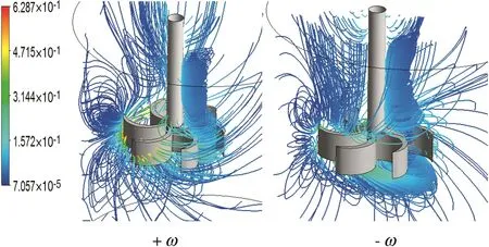
Fig.9.3D fluid flow for different rotational directions,solution E1,Re g=0.1,e/D=0.24.
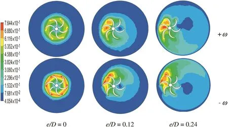
Fig.10.Well-stirred region size for Re g=100,solution E1.

Fig.11.Well-stirred region size for the clockwise rotational direction(+ω),solution E1,e/D=0.12.
Another important point can be emphasized in Fig.12 where the velocity contours are presented for two situations:(+ω)and(-ω).For the same value of the Reynolds numberReg=200,the dead zone between blade Nos.3 and 4 is dissipated in the case(-ω),contrary to the case(+ω)where this dead zone is still present.This is due to the geometrical shape of the blade.
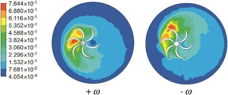
Fig.12.Well-stirred region size for Re g=200,solution E1,e/D=0.12.
Alvarez et al.[14]reported that the mixer eccentricity influences strongly the manifold structure of the liquid flow,resulting thus in destroyed segregated regions and increased axial circulation of the liquid.
The impeller rotational direction(-ω)seems beneficial as it helps eliminate and/or reduce the size of the dead zones for low values of the Reynolds number.But the energy cost is relatively high compared with the case(+ω),as shown in Fig.13.

Fig.13.Power number for e/D=0.24.
5.5.Effect of the fl uid properties
Three emulsion solutions(called E1,E2 and E3)were used in this study and that are found in the food industry.The rheological properties of each solution are summarized in Table 1.This type of fluid has a shear thinning behavior modeled by the Ostwald law.Fig.14 shows the variation of the shear strain rates as a function of the vessel height for the three solutions.This figure is presented at a radial position R*=0.99(i.e.very close to the tank wall)and an angular position θ =0°(i.e.on the extension of blade No.1).Increasing the fluid behavior index gives more shears of the fluid layers.Consequently,the well-mixed zone will be wider(Fig.15).However,the increase in viscous forces requires more energy to complete the stirring operation(Table 3).
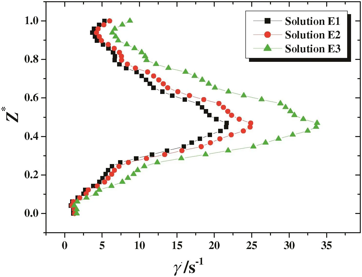
Fig.14.Shear strain rates for the rotational direction(-ω),R*=0.99,Re g=100,θ=0°.
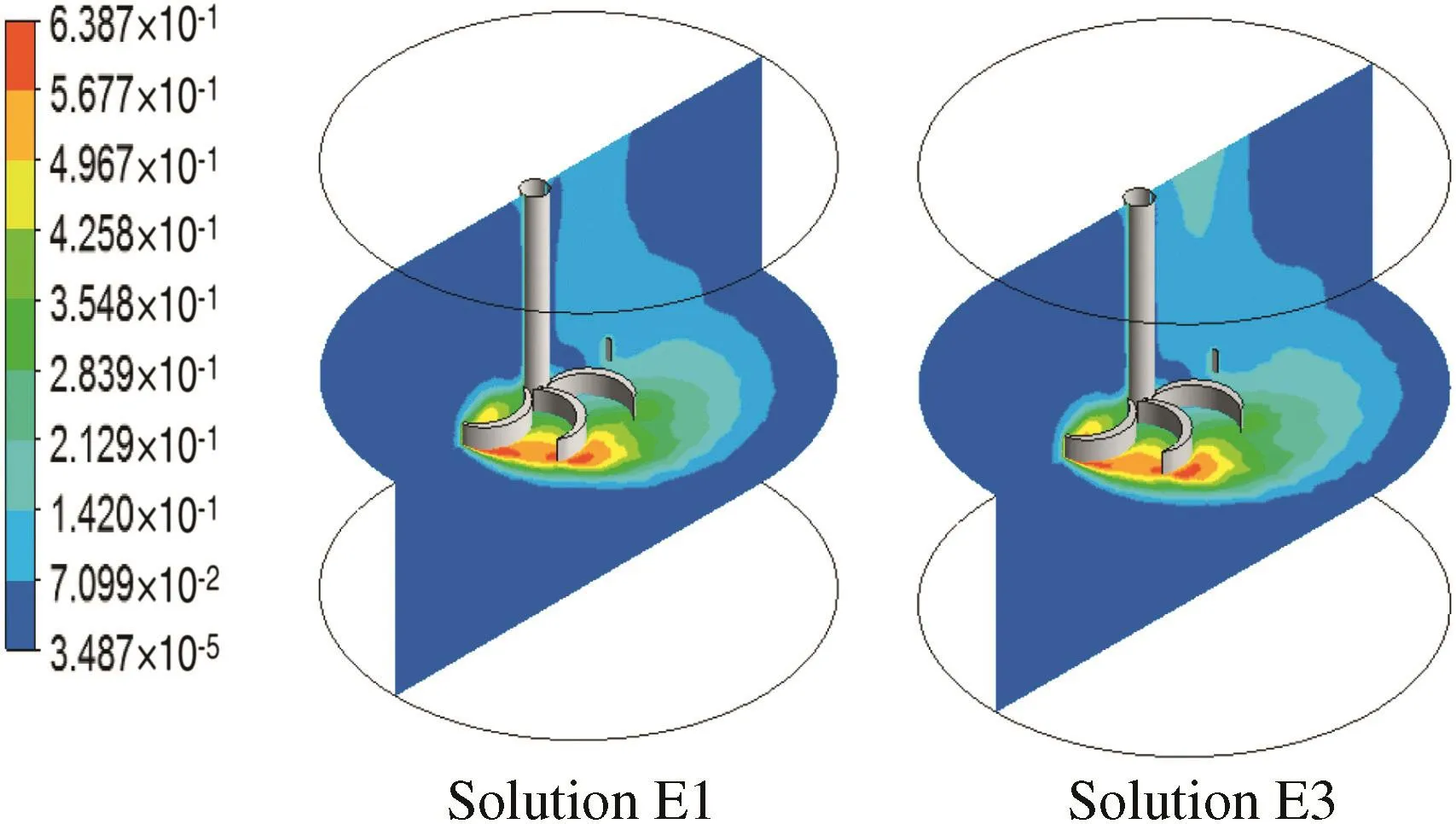
Fig.15.Well-stirred region size for the rotational direction(-ω),Re g=100.

Table 3Power number for e/D=0.12,-ω
6.Conclusions
Results of the numerical investigation of mixing by eccentrically located curved-blade impellers inside an unbaffled cylindrical tank,obtained for food emulsions(shear thinning fluids)within the laminar regime,can be summarized as follows:
·Two vortices are observed for all cases(centric and eccentric configurations),one above the impeller and other below it.The upper vortex is the stronger and dominates the whole motion in the vessel.Flow instabilities are generated in the impeller-wall region because of the circumferential motion around the upper vortex.
·The angular uniformity of the flow discharged from the impeller blades is lost in eccentric configurations.
·The tendency for the destruction of segregated regions was remarked with the increase of the eccentricity.
·The opposite rotational direction(-ω)may reduce the power consumption compared with clockwise rotational direction(+ω).
·The(-ω)case gives a better axial circulation than the(+ω)case.
·The strategy of eccentric shaft reduces the segregated regions in the whole vessel.However,the increase of the impeller eccentricity from 24%to 48%of the vessel diameter generates an additional energetic cost from 50%to 186%,compared to the concentric condition.Also,the lower part of the vessel is not disturbed when the impeller is placed at the mid-height.So,it is advisable to place the mixer at 1/3 of the vessel height and an eccentricity(e/D)between 24%and 48%of the vessel diameter.The critical value ofe/Dis affected by the impeller type,since flow instabilities are observed in the impeller wall region.
Nomenclature
bcblade curvature,m
c impeller clearance from the tank bottom,m
Dtank diameter,m
dbblade diameter,m
dddisk diameter,m
dsshaft diameter,m
dtdisk thickness,m
eimpeller eccentricity,m
hliquid height,m
mconsistency index,Pa·sn
Nimpeller rotational speed,s-1
Nppower number,Np=P∕ ρN3D5
nflow behavior index
P power,W
Qvviscous dissipation function,s-2
Rradial coordinate,m
R* dimensionless radial coordinate,R*=2R∕D
RegReynolds number for a shear thinning fluid,Reg=(ρN2-n·d2) ∕ (m·ks n-1)
Vz,Vθ,Vraxial,tangential and radial velocities,m·s-1
V* dimensionless velocity,V*=V∕ πND
Zaxial coordinate,m
Z* dimensionless vertical coordinate,Z*=Z∕D
α angle of the blade curvature,(°)
shear rate,s-1
θ angular coordinate,(°)
ρ fluid density,kg·m-3
τ shear stress,Pa
ω angular velocity,rad·s-1
[1]M.Basavarajappa,T.Draper,P.Toth,T.A.Ring,S.Miskovic,Numerical and experimental investigation of single phase flow characteristics in stirred tanks using Rushton turbine and flotation impeller,Min.Eng.83(2015)156–167.
[2]A.Busciglio,G.Montante,A.Paglianti,Flow field and homogenization time assessment in continuously-fed stirred tanks,Chem.Eng.Res.Des.102(2015)42–56.
[3]J.P.Torré,D.F.Fletcher,T.Lasuye,C.Xuereb,Single and multiphase CFD approaches for modelling partially baffled stirred vessels:comparison of experimental data with numerical predictions,Chem.Eng.Sci.62(2007)6246–6262.
[4]J.Sossa-Echeverria,F.Taghipour,Computational simulation of mixing flow of shear thinning non-Newtonian fluids with various impellers in a stirred tank,Chem.Eng.Process.93(2015)66–78.
[5]M.Assirelli,W.Bujalski,A.Eaglesham,A.W.Nienow,Macro and micromixing studies in an unbaffled vessel agitated by a Rushton turbine,Chem.Eng.Sci.63(2008)35–46.
[6]B.Wang,J.Zhang,H.E.Youduo,A.N.Shengli,Investigation on eccentric agitation in the stirred vessel using 3D-laser Doppler velocimeter,Chin.J.Chem.Eng.14(2006)618–625.
[7]W.G.Yao,H.Sato,K.Takahashi,K.Koyama,Mixing performance experiments in impeller stirred tanks subjected to unsteady rotational speeds,Chem.Eng.Sci.53(1998)3031–3040.
[8]J.F.Hall,M.Barigou,M.J.H.Simmons,E.H.Stitt,Mixing in unbaffled high-throughput experimentation reactors,Ind.Eng.Chem.Res.43(2004)4149–4158.
[9]J.Karcz,J.Szoplik,An effect of the eccentric position of the propeller agitator,Chem.Pap.58(2004)9–14.
[10]M.Yoshida,Y.Wakura,K.Yamagiwa,A.Ohkawa,S.Tezura,Liquid flow circulating within an unbaffled vessel agitated with an unsteady forward–reverse rotating impeller,J.Chem.Technol.Biotechnol.85(2010)1017–1022.
[11]S.Woziwodzki,Unsteady mixing characteristics in a vessel with forward–reverse rotating impeller,Chem.Eng.Technol.34(2011)767–774.
[12]M.Alvarez,Using Spatio-temporal Asymmetry to Enhance Mixing in Chaotic Flows:From Maps to Stirred Tanks(Ph.D.Thesis)Rutgers University,Piscataway,NJ,2000.
[13]K.C.Ng,E.Y.K.Ng,Laminar mixing performances of baffling,shaft eccentricity and unsteady mixing in a cylindrical vessel,Chem.Eng.Sci.104(2013)960–974.
[14]M.Alvarez,J.Zalc,T.Shinbort,P.Arratia,F.Muzzio,Mechanisms of mixing and creation of structure in laminar stirred tanks,AICHE J.48(2002)2135–2148.
[15]C.Galletti,E.Brunazzi,On the main flow features and instabilities in an unbaffled vessel agitated with an eccentrically located impeller,Chem.Eng.Sci.63(2008)4494–4505.
[16]C.Galletti,S.Pintus,E.Brunazzi,Effect of shaft eccentricity and impeller blade thickness on the vortices features in an unbaffled vessel,Chem.Eng.Res.Des.87(2009)391–400.
[17]G.Montante,A.Bakker,A.Paglianti,F.Magelli,Effect of shaft eccentricity on the hydrodynamics of unbaffled stirred tanks,Chem.Eng.Sci.61(2006)2807–2814.
[18]J.Karcz,M.Cudak,J.Szoplik,Stirring of a liquid in a stirred tank with an eccentrically located impeller,Chem.Eng.Sci.60(2005)2369–2380.
[19]P.R.Gogate,A.B.Pandit,Mixing of miscible liquid with density differences.Effect of volume and density of the tracer fluid,Can.J.Chem.Eng.77(1999)988–996.
[20]S.Woziwodzki,L.Jedrzejczak,Effect of eccentricity on laminar mixing in vessel stirred by double turbine impellers,Chem.Eng.Res.Des.89(2011)2268–2278.
[21]F.L.Yang,S.J.Zhou,C.X.Zhang,G.C.Wang,Mixing of initially stratified miscible fluids in an eccentric stirred tank:detached eddy simulation and volume of fluid study,Korean J.Chem.Eng.30(2013)1843–1854.
[22]J.J.Derksen,Blending of miscible liquids with different densities starting from a stratified state,Comput.Fluids50(2011)35–45.
[23]J.J.Derksen,Direct simulations of mixing of liquids with density and viscosity differences,Ind.Eng.Chem.Res.51(2012)6948–6957.
[24]M.Cudak,J.Karcz,Momentum transfer in an agitated vessel equipped with an eccentrically located HE 3 impeller,Chem.Process.Eng.29(2008)1071–1082.
[25]J.Szoplik,J.Karcz,Mixing time of a non-Newtonian liquid in an unbaffled agitated vessel with an eccentric propeller,Chem.Pap.62(2008)70–77.
[26]J.Szoplik,J.Karcz,The efficiency of the homogenization of non-Newtonian liquid in an agitated vessel with an eccentric propeller,Chem.Process.Eng.30(2009)125–138.
[27]J.Karcz,M.Cudak,Local momentum and heat transfer in a liquid and gas–solid–liquid systems mechanically stirred in a jacketed vessel,Eleventh Eur Conf Mixing.Bamberg,Germany,proceeding,paper P24 2003,pp.447–454.
[28]H.Ameur,M.Bouzit,A.Ghenaim,Numerical study of the performance of multistage Scaba 6SRGT impellers for the agitation of yield stress fluids in cylindrical tanks,J.Hydrodyn.27(2015)436–442.
[29]G.Ascanio,F.A.Tanguy,Mixing of shear-thinning fluids with dual off-centered impellers,Can.J.Chem.Eng.83(2005)393–400.
[30]F.Cabaret,L.Fradette,P.A.Tanguy,Gas–liquid mass transfer in unbaffled dual–impeller mixers,Chem.Eng.Sci.63(2008)1636–1647.
[31]S.Woziwodzki,L.Broniarz-Press,M.Ochowiak,Effect of eccentricity on transitional mixing in vessel equipped with turbine impellers,Chem.Eng.Res.Des.88(2010)1607–1614.
[32]R.K.Thakur,C.Vial,G.Djelveh,M.Labbafi,Mixing of complex fluids with flat-bladed impellers:effect of impeller geometry and highly shear-thinning behavior,Chem.Eng.Process.43(2004)1211–1222.
[33]M.Alliet-Gaubert,R.Sardeing,C.Xuereb,P.Hobbes,B.Letellier,P.Swaels,CFD analysis of industrial multi-staged stirred vessels,Chem.Eng.Process.45(2006)415–427.
[34]M.Alvarez,P.E.Arratia,F.J.Muzzio,Laminar mixing in eccentric stirred tank systems,Can.J.Chem.Eng.80(2002)546–557.
[35]C.Ford,F.Ein-Mozaffari,C.P.J.Bennington,F.Taghipour,Simulation of mixing dynamics in agitated pulp stock chests using CFD,AIChE J.52(2006)3562–3569.
[36]W.Kelly,B.Gigas,Using CFD to predict the behaviour of power law fluids near axial flow impellers operating in the transitional flow regime,Chem.Eng.Sci.58(2003)2141–2152.
[37]C.Rivera,S.Foucault,M.Heniche,T.Espinsoa-Slares,P.A.Tanguy,Finite element modelling of the laminar and transition flow of the Superblend dual shaft coaxial mixer on parallel computers,Chem.Eng.Sci.64(2009)4442–4456.
[38]L.Pakzad,F.Ein-Mozaffari,S.R.Upreti,A.Lohi,Characterisation of the mixing of non-Newtonian fluids with a scaba 6SRGT impeller through ERT and CFD,Can.J.Chem.Eng.91(2013)90–100.
[39]J.Aubin,I.Naude,C.Xuereb,J.Bertrand,Blending of Newtonian and shear-thinning fluids in a tank stirred with a helical screw agitator,Chem.Eng.Res.Des.78(2000)1105–1114.
[40]I.Naude,Direct Simulations of Impellers in a Stirred Tank.Contribution to the Optimization of the Choice of an Agitator(Ph.D.thesis)INPT,France,1998.
[41]H.Ameur,M.Bouzit,M.Helmaoui,Hydrodynamic study involving a maxblend impeller with yield stress fluids,J.Mech.Sci.Technol.26(2012)1523–1530.
[42]B.C.H.Venneker,J.J.Derksen,H.E.A.Van den Akker,Turbulent flow of shear-thinning liquids in stirred tanks—the effects of Reynolds number and flow index,Chem.Eng.Res.Des.88(2010)827–843.
[43]G.B.Tatterson,Fluid Mixing and Gas Dispersion in Agitated Tanks,McGraw-Hill,New York,1991 221.
 Chinese Journal of Chemical Engineering2016年12期
- Chinese Journal of Chemical Engineering的其它文章
- Statistical mechanics and artificial intelligence to model the thermodynamic properties of pure and mixture of ionic liquids☆
- Modification and sequential treatment of EU-1 zeolite in mild alkali and alkaline-acid conditions
- Catalytic kinetics of dimethyl ether one-step synthesis over CeO2–CaO–Pd/HZSM-5 catalyst in sulfur-containing syngas process☆
- Development of a bifurcation analysis approach based on gPROMS platform☆
- A comprehensive fractal char combustion model☆
- Molar volume of eutectic solvents as a function of molar composition and temperature☆
