
Modeling and simulation of urea-water-solution dropletevaporation and thermolysis processes for SCR systems☆
2016-06-01 03:01XuboGanDongweiYaoFengWuJiaweiDaiLaiWeiXingwenLi
Xubo Gan,Dongwei Yao,Feng Wu,Jiawei Dai,Lai Wei,Xingwen Li
Institute of Power Machinery and Vehicular Engineering,Zhejiang University,Hangzhou 310027,China
1.Introduction
Diesel engines are widely used in vehicle,marine and construction machinery.Compared with gasoline engines,diesel engines with high compression ratio have better torque density and lower fuel consumption.However,lean burning condition during diffuse combustion process leads to higher NOXand PM emissions[1].Moreover,there is a trade-off relationship between NOXand PM emissions[2].With the increasingly stringent emission regulations,integrated strategies combining incylinder combustion optimization and exhaust gas after treatment for diesel engine emission control have become necessary.Selective catalytic reduction(SCR)is the most widely used technology to reduce NOXemissions from diesel engines[3].
Since ammonia is produced from urea-water-solution(UWS,32.5 wt%urea,known as Adblue in Europe and Diesel Exhaust Fluid,DEF in America),the ammonia production process is very important for the performance of SCR systems.The conversion efficiency of urea decomposes to ammonia and the concentration uniformity of ammonia within the monolith entrance strongly affects the DeNOx process.The conversion efficiency of urea decomposition depends on the quality of UWS spray,exhaust temperature and spray/wall interaction.Poor quality spray produces large droplets which will increase the evaporation time,while low exhaust temperature will reduce evaporation rate.Both of them are adverse for evaporation process.Spray/wall impingement can be hardly avoided under actual conditions.It causes local cooling of the wall and wall film will occur if wall temperature decreases below a critical temperature[4].Moreover,side reactions may also occur during spray/wall impingement,producing undesired byproducts such as biuret,cyanuric acid(CYA),ammelide,ammeline,melamine and more complex polymerization products[5-7].These undesired byproducts can form solid deposits,which may block the exhaust pipe and catalyst leading to higher exhaust pressure and lower conversion efficiency of urea decomposition.Thus the performance of SCR systems deteriorates.Also,the concentration uniformity of ammonia is connected with exhaust flow and spray/wall impingement.Uneven concentration distribution leads to uneven distribution of catalyst loading which not only causes ammonia slip but also accelerates catalyst aging.
The evaporation and the rmolysis processes of UWS droplets have been investigated for decades through experimental and simulation methods.Literatures[8-11]investigated the evaporation characteristics of a single UWS droplet using a suspended droplet experiment.The droplet evaporation coefficients under different ambient temperatures were extracted from the temporal history of squared droplet diameter by measuring the slope of its linear regression part[8].Three stages were found during UWS droplet heating process[9].D-square law(D2law)was found in the first stage which indicated that only water evaporation took place in this stage.The other two stages were mainly caused by urea the rmolysis process.Formation of bubbles and foams and expansion of droplet size were observed in the second stage.In the last stage,crystallization was observed.UWS droplet behaved differently depending on its ambient temperature[8,10].At high temperature,complicated behaviors such as bubble formation,distortion and micro-explosion can be observed.However,these phenomena became very weak and even disappeared as temperature decreases.
Stradella[12]and Chen[13]investigated the urea thermolysis process using a differential scanning calorimeter(DSC),thermogravimetric with evolved gas analysis(TG-EGA),thermogravimetric with differential thermal analysis(TG-DTA),and mass spectrometry(MS).They found that ammonia and iso-cyanic were produced during urea thermolysis process,besides,high molecular compounds such as biuret,CYA,ammelide and ammeline also appeared in their investigation.Schaber[14,15]studied the urea thermal decomposition in an open vessel condition with various measurements including TGA,high performance liquid chromatography(HPLC),Fourier transform-infrared(FT-IR)and ammonium ion-selective electrode(ISE).Details of the reaction mechanism for urea thermolysis were proposed,and urea thermolysis process was divided into four reaction regions based on differentambient temperatures. Lundström[[16]studied the ammonia and iso-cyanic production during thermal decomposition of urea under flow reactor conditions by using DSC and FT-IR.Different heating rates and types of reactors including monolith and cup were compared to investigate their influence on ammonia and iso-cyanic production process.Eichelbaum[17]compared the FTIR spectrums of CYA,ammelide,and a urea sample which was isothermally treated in dry N2for 1 h at 270°C.Consequently,the results showed that the main products of urea decomposition at 270°C were CYA and ammelide.
Numerical simulation methodology is widely used in Scientific research for its low cost and high efficiency.Furthermore,it can provide lots of information which cannot be measured in experiments.Various models have been proposed to simulate the UWS evaporation and decomposition processes.Wurzenberger[18]developed a UWS droplet evaporation modelin which the heatand mass transfer processes are described by a model originally derived by Dukowicz.However,the model was limited to the assumption that the Lewis number is unity(Le=1).Tian Xinna[19]developed a UWS dropletevaporation model which optimized the location of injector in SCR system through the aspect of UWS droplet depletion process,but the Lewis number was still assumed to be 1.Abramzon and Sirignano[20]re fined the classical model of droplet evaporation by employing the so called “ film”theory[21],the “Modified”Nusselt and Sherwood numbers were used to demonstrate the effect of Stefan flow.Literatures[4,22,23,24]applied the above Abramzon-Sirignano model into UWS droplet evaporation process.This model gave no limitation of the Lewis number,but its iteration process would become complicated.Abu-Ramadan[25]applied the mass analogy model of droplet evaporation to calculate the behavior of UWS droplet in a stagnant heated environment,the logarithmic term appeared in Abramzon-Sirignano model was canceled.The difference between Abramzon-Sirignano and mass analogy models were discussed in detail by Miller[26].The evaporation of water can lead to a spatialurea concentration gradient at the droplet surface,and the solved urea at the droplet surface can cause a decrease of the evaporation rate.Birkhold[23]used the correlation from the Perman and Lovett,Ebrahimian[27]applied the NRTL activity model to calculate the vapor pressure of UWS,and Kontin[28]Modified the evaporating mass flow rate of Abramzon-Sirignano model with the introduction of mass flow reduction coefficient.Although many evaporation models have been developed,the different evaporation behaviors of UWS droplets caused by different ambient temperatures are not considered yet.
Some numerical models were proposed to predict UWS thermolysis process.In general,these models can be divided into two types:one was global kinetic model which urea decomposed into ammonia and isocyanic acid directly[4,23,24,29],the other was semi-detailed kinetic model which considered not only ammonia and iso-cyanic acid production but also solid by-product formation[27,30,31].Consequently,the former model was simple but cannot predict the formation of deposits resulting from urea decomposition whereas the latter one can though it was more complicated.In Ebrahimian's[27]study,urea thermolysis reactions were supposed to take place in solid phase,solid byproducts were supposed to be biuret,CYA and ammelide since they were the main components during urea thermolysis in experiments.The kinetic scheme consisted of12 steps in which the firstnine steps occurred in dry media while the last three steps took place in UWS.In his PHD thesis[30],the thermolysis model was implemented into a CFD code to simulate the deposit formation in a typical automotive SCR system.However,only the results at time 0.01 s were presented in his thesis which may not be valuable in estimating deposit formation.In Brack's[31]work,kinetic scheme during urea thermolysis became even more complicated which contained 15 steps.Besides biuret,CYA and ammelide as the main components,other intermediate products like biuret-matrix,triuret were also taken into consideration.In addition,geometric effects for example the influence of the surface area were also reflected in the model.However,the energy equation of urea thermolysis is neglected in both Ebrahimian's and Brack's work.
Although much work has been done in computational studies of UWS droplet evaporation and thermolysis,there are still problems thatremain to be solved.It seems that Abramzon-Sirignano model is the most widely used in UWS droplet evaporation process.However,comparisons of computational results and experimental data show large deviations which are mainly caused by the differentevaporation behaviors atdifferent ambient temperatures.In addition,urea thermolysis is complex and many intermediate processes and products remain unknown.A detailed kinetic model of urea thermolysis is useful especially in deposit prediction of SCR systems.Nevertheless,a combination of thermolysis model and CFD method calculating deposit formation costs too much computationalresources.A simplified approach to estimate the depositformation in SCR systems would be valuable for deposit mitigation.
In this study,a computational model of UWS droplet evaporation and thermolysis is proposed.An adjustment coefficient is applied into Abramzon-Sirignano evaporation model to optimally match the experimental data.A semi-detailed kinetic scheme of urea thermolysis is developed based on Ebrahimian's work[27].The energy equation of urea thermolysis is taken into consideration when calculating the UWS droplet depletion process.Next,the evaporation characteristics and decomposition efficiency of a single UWS droplet are simulated,and the deposit formation is estimated through the thermolysis model.
2.Model Formulation
2.1.Droplet dynamics
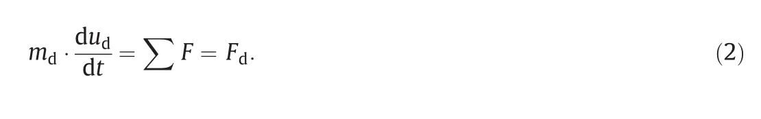
Droplet motion is taken into consideration as it influences the heat and mass transfer between droplet and exhaust gas.For simplicity,the flow is treated as one-dimensional and the initial velocity of droplet is parallel to the flow direction.The differential equation for the trajectory and velocity of a droplet is as follows:

Drag force is the mostdominating force when UWS injected into exhaust gas.Buoyancy force can be neglected because of the onedimensional assumption.Therefore,the motion of droplet can be:
Drag force is calculated as:
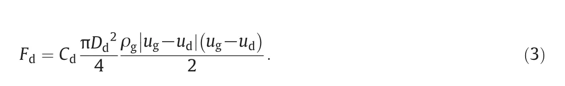
Cdis the drag coefficient which is a function of the droplet Reynolds number.Schiller and Naumann's formula is used[32]:
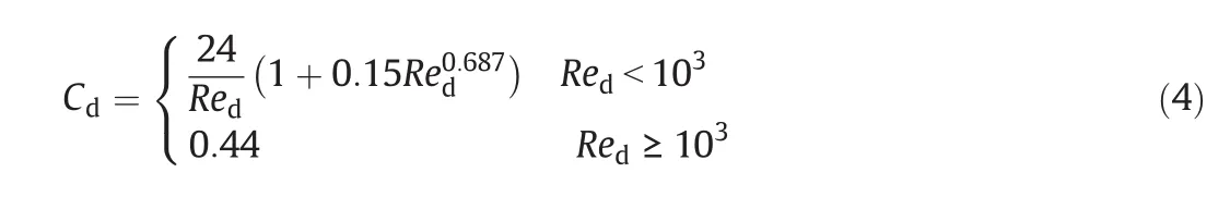
The droplet Reynolds numberRedis shown in the following equation where ρmixis the average gas density and μg,mixis the average gas viscosity near the droplet surface.

Combining all these above,the momentum equation of the droplet can be written as:

The momentum transfer from droplet to exhaust gas is neglected since the mass of droplet is very small comparing to exhaust gas in SCR systems.Therefore,it can be concluded that the motions of droplet have no effect on exhaust gas.
2.2.Evaporation model
The evaporation model in current study is based on Abramzon-Sirignano model[20].Following assumptions are made to simplify the mathematical model:
(1)The droplet is spherical symmetry;
(2)The droplet surface is surrounded by a quasi-steady gas film and both liquid and gas phases surrounding droplet is at thermodynamic equilibrium;
(3)The rapid mixing(RM)model[23]is used which means uniform temperature,concentration and fluid properties in droplet.
Water evaporates first from UWS for its lower boiling temperature.In Abramzon-Sirignano model,mass transfer equation is:
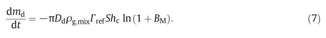
However,large deviations can be observed between computational results and experimental data as discussed later.Considering that UWS droplet behaves differently depending on its ambient temperature,an adjustment coefficient depending on exhaust temperature is introduced to the mass transfer equation(Eq.(7)).Through calibration,we finally determine the adjustment coefficient as(T∞/673).Consequently,the mass transfer equation in this study is as follows:

BMandBTare called the Spalding mass and heat transfer numbers.They are calculated as:

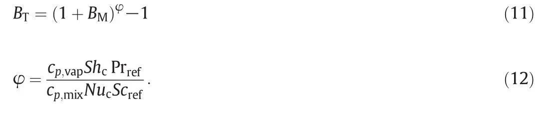
NucandShcare the Modified Nusselt and Sherwood numbers which are calculated by theNu0andSh0numbers of the non-evaporating droplet[32]
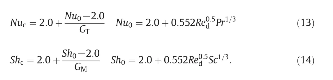
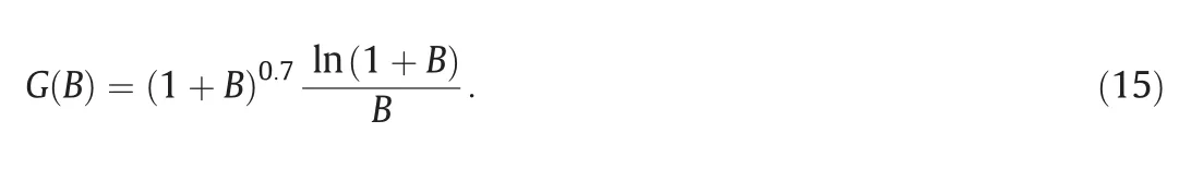
GTandGMare the correction factors related to Stefan flow,and they have the universal function:
2.3.Thermolysis model of urea
A two step method is used in this study[4,19,22,23,24,25,27,28]:water evaporates first from the droplet for its lower boiling temperature,after all water is gone,the remaining pure urea begins to decompose.The thermolysis model is based on Ebrahimian's work[27].Some assumptions are made to simplify urea thermolysis process:
(1)Urea related deposit components are assumed to be solid urea,biuret,CYA,ammelide,others are all neglected;
(2)Reactions take place in solid phase in CSTR reactor;
(3)The species are randomly distributed on a uniform surface.A urea site density of 5.3 × 10⁻¹⁰mol·cm-2is deduced from the tetragonal lattice parameters of solid urea;
(4)The number ofsites occupied by each molecule of species is fixed and the sites are conserved throughout reaction process.Among them,urea molecular occupies 2 sites,NH+and NCO-occupy 1 site,and so on.
In author's opinion,there's no evidence that urea decomposes differently between dry media and UWS,which is differentfrom Ebrahimian's view[27].In literature[16],the different behaviors of urea thermolysis between dry media and UWS was mainly caused by different containers(monolith and cup).Hence,only nine reactions are taken into consideration in the current study.The kinetic scheme for urea thermolysis is shown in Table 1.
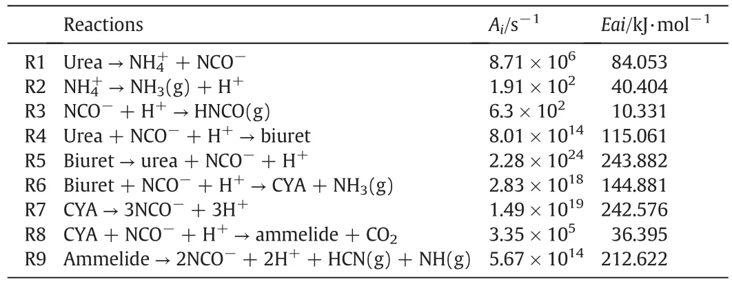
Table 1Kinetic scheme for urea thermolysis
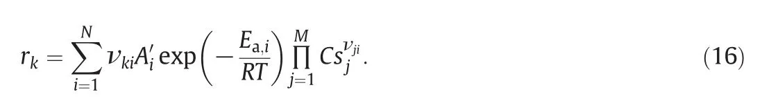
The net raterfor each reaction is:
Ai′is related to the pre-exponentialfactorAishown in Table 1viathe site density δ:
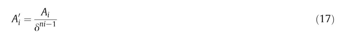
wherenirepresentstheith reaction order.The active surfaceSis de fined as:

Active surface is held constant throughout the reaction process,and it can be used to calculate the overall mass change.Surface concentration of each species is calculated as:

When calculating the UWS droplet depletion process,the energy conservation equation is taken into consideration.The convective heat transfer from ambient to urea dropletQg,sis consumed by droplet heatingQland urea thermolysisQth,u:

Each term in Eq.20 is calculated as follows:

The enthalpy changes of the multiple reactions are difficult to calculate since the lack of thermodynamic parameters of the intermediate products like H+,NH4+,and NCO-as well as solid by-products like biuret,CYA,and ammelide.For simplicity,a fictive heat of urea thermolysisHth,uis used which assumes urea sublimation and decomposition proceed in one fast way[19,23,24].And the heat consumed by urea thermolysis is calculated through Eq.(23).
2.4.Material and transport properties
Material properties including specific heat,thermal conductivity,and dynamic viscosity of air and water vapor used in this study refer to literature[33](Table 2).
The mass fraction of water vapor at droplet surface can be determined according to the Raoult's law for the assumption that both liquid and gaseous phases are in a thermodynamic equilibrium state around the droplet surface:

Since temperature is a crucial factor to material properties,1/3 mixing rule is used for the reference temperature of the film:

The physical properties like viscosity and thermal conductivity for gaseous and liquid mixture surrounding droplet are calculated as:

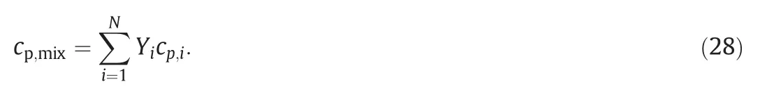
The specific heat for the gaseous mixture is calculated as:
The density of gaseous mixture and UWS droplet is calculated as:

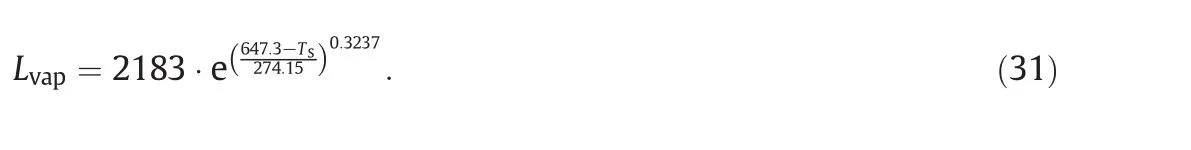
The latent heat of water vaporization is related to droplet temperature[34]:
The vapor pressure of UWS is calculated based on the NRTL activity model[27].The combined fictive heat value of urea thermolysis is3096 kJ·kg-1.The specific heat of urea is 2063 kJ·kg-1·K-1.The mass diffusion coefficient is calculated as follows,where Γ0is the mass diffusion coefficient under condition ofT0andP0:
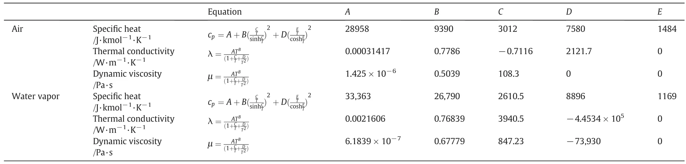
Table 2Physical properties for the gaseous and liquid materials

2.5.Numerical solution procedure
The mathematical model of UWS droplet evaporation and thermolysis described above is implemented with a Fortran code developed in house.In order to simplify the programming procedure,Euler explicit finite difference method is used in mass,momentum,and energy as well as reaction rate equations.
3.Results and Discussion
3.1.Validation of evaporation and thermolysis model
According to Eq.(8),the following equation can be deduced by integral which is the well knownD2-law.Keis de fined as the evaporation coefficient.

The Abramzon-Sirignano model is firstly developed for fuel spray combustion calculation and it is now widely used in UWS droplet evaporation.However,the accuracy of the model has not been validated in the entire temperature range from 423 to 873 K in previous studies.As a matter of fact,the calculation results of Abramzon-Sirignano model overestimate the evaporation coefficient of UWS droplet in low temperature region and underestimate it in high temperature region.Accordingly,a mass transfer equation introducing an adjustment coefficient is proposed(Eq.10).Fig.1 shows the comparison of original Abramzon-Sirignano model,simulation results after correction and experimental data[8]of evaporation coefficient.It is obvious that the precision of the model has been much improved after correction.

Fig.1.Comparison of original Abramzon-Sirignano model,simulation results after correction and experimental data of evaporation coefficient.
Urea thermolysis model developed in this study is mainly used for deposit calculation.To improve the accuracy of the model,the kinetic parameters suggested by Ebrahimian[27]are re-optimized based on Schaber's data[15],and the optimized parameters are presented in Table 1.Detailed information of the methodology and conclusions is presented in literature[35]written by authors.
3.2.Validation of UWS droplet depletion model
Combining the evaporation and thermolysis models proposed above,the UWS droplet depletion process can be simulated.Fig.2 shows the simulated UWS droplet depletion process compared to experimental data by Wang[8].The initial mass fraction of urea in the droplets was set to 40%suggested by Lundström[22].Two stages can be obtained during depletion process according to different slopes of the curve.The first stage is ascribed to water content evaporation.It is obvious that the simulation results of evaporation process match the experimentaldata quite well attemperature from 473 K to 723 K.The second stage is ascribed to the urea thermolysis.Relatively speaking,the simulation error increases when temperature exceeds 573 K.The reason is that droplet micro-explosion begins to appear when temperature exceeds 573 K which will accelerate the decomposition rate.For another reason,conduction heat transfer between fiber and droplet is not taken into consideration in the proposed model as well.However,the overall agreement is good,and the simulation results capture the right tendency of the droplet depletion process.
3.3.Evaporation characteristics and decomposition efficiency of a single UWS droplet
Fig.3 shows the relation of evaporation time,relative velocity and droplet initial diameter.Apparently,the increase of droplet diameter can extend the evaporation time,while the increase of relative velocity between droplet and exhaust gas can promote the heat transfer between them.The result of which is the acceleration of the evaporation process.In general,relative velocity has more significant effect on large droplets.The extension of the evaporation time can increase the probability of spray/wall impingement and deposit formation in SCR system.Hence,optimization of UWS injector system to reduce droplet initial diameteris very helpful to droplet evaporation and ammonia production.Furthermore,the increase of relative velocity between droplet and exhaustgas indeed accelerates the evaporation rate,however,it reduces the residence time of droplet in the exhaust gas which is bad for droplet evaporation.
Fig.4 shows the relation of evaporation time,exhaust temperature and droplet initial diameter.It indicates that droplet evaporation time depends greatly on the droplet diameter and exhaust temperature.A larger droplet needs more time to evaporate,so it may travel farther in the exhaust pipe.And high exhaust temperature can accelerate the evaporation process which means less evaporation time.
Fig.5 shows the relation of urea decomposition efficiency and the residence time.The decomposition efficiency is de fined as the ratio of decomposed mass of pure urea and the initial mass of urea.It is obvious that higher temperature and longer residence time result in higher decomposition efficiency.Furthermore,the figure shows that the residence time required by UWS droplets complete decomposition is in second level.Most SCR systems of automotive applications cannot provide such long time for UWS droplet decomposition,leading to the accumulation of non-decomposed urea at catalyst entrance,which is a crucial reason for deposits of SCR systems.
3.4.Simulation of deposit formation
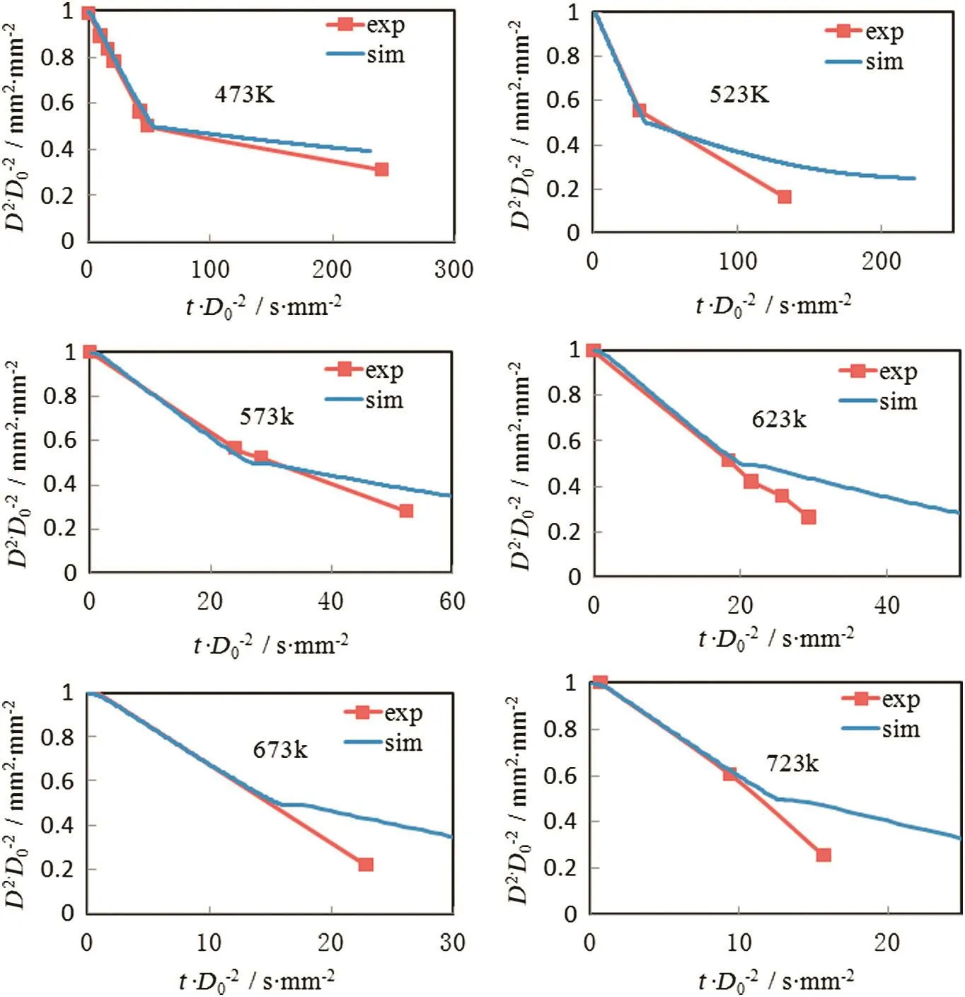
Fig.2.Simulated UWS droplet depletion process at 473 K,523 K,573 K,623 K,673 K and 723 K compared to experimental data by Wang[8].
Exhaust pipe is one of the most probable parts where urea deposits occur.Based on the model assumptions,time required by urea complete decomposition is independent of its initial mass,and urea thermolysis process is only related to temperature.Therefore,the thermolysis process of a single UWS droplet can be treated as the urea thermolysis of a whole SCR system approximately.And deposit components and deposit yield of SCR systems can be estimated based on reaction temperature.Fig.6 shows the experimental results of deposits formed at different wall temperatures conducted by Tenneco Incorporation[7].When wall temperature is under 403 K,it is believed that most nondecomposed urea left behind after all the water evaporated..Hence these deposits are soluble in water.Deposits 3 form at 416 K.These deposits are opaque and difficultto remove.Deposits 4 are created at temperature of 448 K,They require a scraper to remove and are insoluble in water.This is only a qualitative study of deposit formation and it's difficult to know why deposits behave differently through this results.However,based on the proposed urea thermolysis model,deposit components on exhaust pipe can be calculated.Fig.7 shows the simulation results of deposit components at different wall temperature. Deposit yield is defined as the ratio ofdepositmass and initialurea mass.It can be seen that at the temperature of 416 K,most of deposit component is urea.Though increasing,the amount of biuret still keeps at a low level.It's difficult to remove because 416 K is higher than urea's melting point which means phase changing occurs during the experiment.When temperature is 448 K,urea,biuret,and a small amount of CYA are included in deposits.Thus,the experiment phenomenon can be explained by the poor solubility of biuret and CYA.
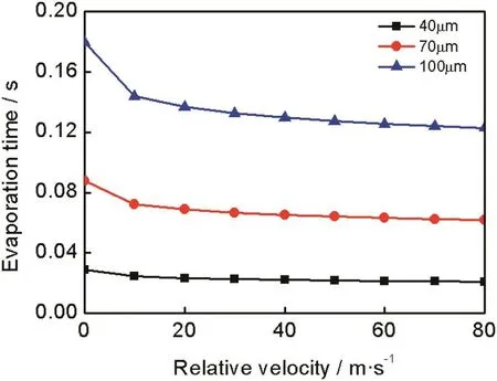
Fig.3.Relation of evaporation time,relative velocity and droplet initial diameter(T∞=673 K,P∞=0.101325 MPa,T s,0=300 K,Y u=0.325).

Fig.4.Relation of evaporation time,exhaust temperature and droplet initial diameter(T∞=673 K,P∞=0.101325 MPa,T s,0=300 K,Y u=0.325,u∞=0,u d=0).

Fig.5.Relation of urea decomposition efficiency and the residence time(D0=40 μm,P∞=0.101325 MPa,T s,0=300 K).
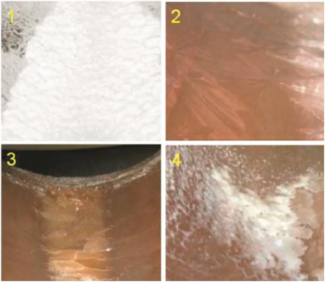
Fig.6.Deposits formed at different temperatures.

Fig.8.Simulation results of deposit components under different temperatures.
Deposit components are highly dependent on temperature.Fig.8 shows the simulation results of deposit components under different temperatures.The simulation is conducted at constant temperature starting from 406 K to 646 K and each temperature maintains 1800 s to get stable results.Urea appears in the temperature range of 406-456 K as a main component of deposits.Along with the rise of temperature,urea content reduces gradually.Biuret forms in the temperature range of 416-466 K and reaches its maximum at 446 K.CYA is a common deposit component forming from 446 K to 566 K,the amount of which is quite stable in the range of 486-526 K.Ammelide formation requires the highest temperature among these four main deposit components.It appears from 466 K to 626 K and it becomes the main component when temperature exceeds 566 K,at which CYA decomposes completely.An interesting phenomenon can be obtained when observing the relation between deposit yield and temperature.It is generally accepted that there is a strong negative correlation between them.Nevertheless,the simulation results show a smaller deposit yield around 450 K and deposit yield even increase along with temperature rising from 466 K to 516 K.In order to explain this phenomenon,the simulated reaction rate at 450 K and 480 K during urea thermolysis is shown in Fig.9.The reaction rates of R7-R9 are zero since low temperature.Actually,deposityield is determined by the ratio of solid by-products and gasphase products if reaction time is long enough.Solid by-products are produced through R4,R6,and R8,while gas-phase products are produced through R2,R3 and R6.At temperature 450 K,the overall reaction rates are slow,and the ratio of(R4+R6)/(R2+R3+R6)is relatively low,which leads to smaller deposit yield.On the other hand,at temperature 480 K,the overall reaction rates get fast,and the ratio of(R4+R6)/(R2+R3+R6)becomes higher so that deposit yield increases.
Besides temperature,deposit yield is also influenced by reaction time.Fig.10 shows the relation among deposit yield,reaction time and temperature.Generally speaking,higher temperature and longer reaction time lead to smaller deposit yield,and no deposits form if temperature exceeds 630 K.When temperature is low,reaction time has significant effect on deposit yield since the lower reaction rate.When temperature gets higher,reaction rate also accelerates,hence little influence can be found from reaction time.In fact,deposit yield is determined by the ratio of solid by-products and gas-phase products as mentioned above.This ratio is very low in low temperature(>406 K).Consequently,deposityield would be very small with adequate reaction time.An extreme example is that deposit yield becomes 0 at 406 K with infinity reaction time.One application of this conclusion in SCR system is for injector deposit prevention.The reaction time in injector can be treated as infinity,therefore,a temperature range from 406 K to about 450 K is appropriate for injector deposit prevention.
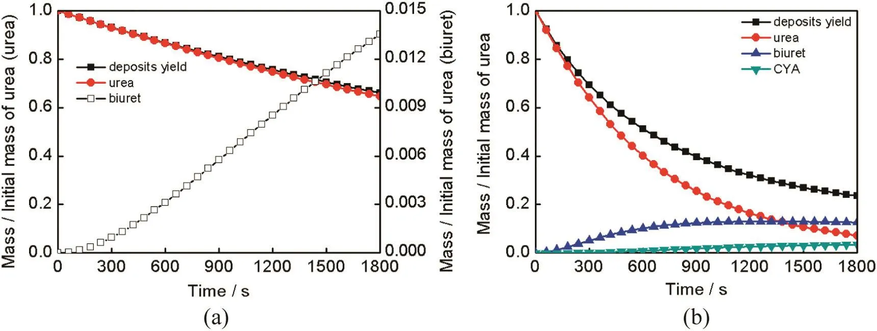
Fig.7.Simulation results of deposit components at different wall temperatures(a)416 K,(b)448 K.

Fig.9.Simulated reaction rate at 450 K and 480 K during urea thermolysis(a)450 K,(b)480 K.
4.Conclusions
A UWS droplet evaporation and thermolysis model is developed in the current study.The well known Abramzon-Sirignano evaporation model is Modified by introducing an adjustment coefficient.A semidetailed kinetic scheme of urea thermolysis is developed based on Ebrahimian's work.The comparison between simulation and experimental results showed good agreement.
The evaporation characteristics of a single UWS droplet depend on droplet diameter,temperature and relative velocity.Smaller droplet diameter,higher temperature and relative velocity lead to shorter evaporation time.Hence,optimization of UWS injector system which reduces droplet initial diameter is very helpful to UWS droplet evaporation and ammonia production.A crucial reason for deposits of SCR systems is that the long residence time required for UWS droplets to decompose completely.
Temperature is the decisive factor for deposit components.Deposit yield is strongly affected by temperature and reaction time.Overall,higher temperature and longer reaction time lead to smaller deposit yield,and no deposits form when temperature exceed 630 K.Essentially,deposit yield is determined by the ratio of solid by-products and gasphase products with adequate reaction time and it would become very small under the condition of enough reaction time in low temperature range(406-405 K).

Fig.10.Relation of deposit yield,time and temperature.
Nomenclature
Apre-exponential factor,s-1
BM,TSpalding number
Cdrag coefficient
Cssurface concentration,mol·cm-2
cpspecific heat,J·kg-1·K-1
Ddroplet diameter,m
Eaactivation energy,J·mol-1
Fforce,N
GM,Tfilm thickness correction factor
Hth,ufictive heat of urea thermolysis,kJ·kg-1
Keevaporation coefficient
Llatent heat,kJ·kg-1
mmass,kg
NuNusselt number
namount of substance,mol
Ppressure,Pa
PrPrandtl number
Q.heat transfer rate,W
ReReynolds number
rreaction rate,mol·cm-2·s-1
S active surface,cm2
ScSchmidt number
ShSherwood number
Ttemperature,K
ttime,s
uvelocity,m·s-1
Wmolecular weight,g·mol-1
Xmole fraction
xdroplet position,m
Ymass fraction
Γ mass diffusion coefficient,m2·s-1
γ activity coefficient
δ site density,mol·cm-2
λ heat conductivity,W·m-1·K-1
μ dynamic viscosity,Pa·s
ν stoichiometric coefficient
ξ a parameter de fined in Eq.(27)
ρ density,kg·m-3
σ number of sites occupied by each molecule of species
φ non-dimensional parameter de fined by Eq.(12)
Ω physical properties(viscosity and thermal conductivity)
Subscripts
adblue urea water solution
C corrected
d droplet
film gas film
g gas phase
lliquid
mix exhaust gas and water vapor mixture
ref. film(reference)temperature
s surface
sat saturation
th thermolysis
u urea
vap vapor
w water
∞ ambient
0 initial
[1]L.Hua,Y.G.Zhao,J.Hu,T.Tang,S.J.Shuai,Comparison between air-assisted and airless urea spray for diesel SCR system by PDA and CFD,SAE Paper No.2012-01-1081,SAE Technical Paper,2012.
[2]H.Y.Dong,S.J.Shuai,J.X.Wang,Effect of urea thermal decomposition on diesel NOx-SCR aftertreatment system,SAE Paper No.2008-01-1544.SAE Technical Paper,2008.
[3]Y.Gao,T.Luan,T.Lv,K.Cheng,H.Xu,Performance of V2O5-WO3-MoO3/TiO2catalyst for selective catalytic reduction of NOXby NH3,Chin.J.Chem.Eng.21(1)(2013)1-7.
[4]F.Birkhold,U.Meingast,P.Wassermann,O.Deutschmann,Analysis of the injection of urea-water-solution for automotive SCR DeNOX-systems:Modeling of two-phase lf ow and spray/wall-interaction,SAE paper No.2006-01-0643.SAE Technical Paper,2006.
[5]V.O.Strots,S.Santhanam,B.J.Adelman,G.A.Grif fin,E.M.Derybowski,Deposit formation in urea-SCR systems,SAE paper No.2009-01-2780.SAE Technical Paper,2009.
[6]L.F.Xu,W.Watkins,R.Snow,G.Graham,R.Mccabe,C.Lambert,R.O.Carter,Laboratory and engine study of urea-related deposits in diesel urea-SCR aftertreatment systems,SAE paper No.2007-01-1582.SAE Technical Paper,2007.
[7]Zheng,G.Y.,File,A.,Kotrba,A.,Floyd,R.,Investigation of urea deposits in urea SCR systems for medium and heavy duty trucks.SAE paper No.2010-01-1941.SAE Technical Paper(2010)
[8]T.J.Wang,S.W.Baek,S.Y.Lee,D.H.Kang,G.K.Yeo,Experimental investigation on evaporation of urea-water-solution droplet for SCR applications,AIChE J.55(12)(2009)3267-3276.
[9]S.N.A.Musa,M.Saito,T.Furuhata,M.Arai,Evaporation characteristics of a single aqueous urea solution droplet,ICLASS-2006,Kyoto,Paper ID ICLASS06-195,2006.
[10]Z.Huang,K.Yin,Z.Zhou,Z.Wang,W.Yang,J.Zhou,Experimental investigation on evaporation characteristics of urea-aqueous-solution droplet,Chem.Ind.Eng.Progr.33(4)(2014)817-823(In Chinese).
[11]L.Zhong,Q.Song,Q.Z.Huang,Q.Yao,Evaporation and conversion characterizations of urea-water-solution droplets within the temperature window for SNCR DeNOx,Proc.CSEE33(26)(2013)21-26(In Chinese).
[12]L.Stradella,M.Argentero,A study of the thermal decomposition of urea,of related compounds and thiourea using DSC and TG-EGA,Thermochim.Acta219(27)(1993)315-323.
[13]J.Chen,K.Isa,Thermal decomposition of urea and urea derivatives by simultaneous TG/(DTA)/MS,J.Mass Spectrom.Soc.Jpn.46(4)(1998)299-303.
[14]P.M.Schaber,J.Colson,S.Higgins,E.Dietz,D.Thielen,B.Anspach,J.Brauer,Study of the urea thermal decomposition(pyrolysis)reaction and importance to cyanuric acid production,Am.Lab.31(16)(1999)13-21.
[15]P.M.Schaber,J.Colson,S.Higgins,D.Thielen,B.Anspach,J.Brauer,Thermal decomposition(pyrolysis)of urea in an open reaction vessel,Thermochim.Acta424(1)(2004)131-142.
[16]A.Lundström,B.Andersson,L.Olsson,Urea thermolysis studied under flow reactor conditions using DSC and FT-IR,Chem.Eng.J.150(2)(2009)544-550.
[17]M.Eichelbaum,R.J.Farrauto,M.J.Castaldi,The impact of urea on the performance of metal exchanged zeolites for the selective catalytic reduction of NOx:part I.Pyrolysis and hydrolysis of urea over zeolite catalysts,Appl.Catal.B Environ.97(1)(2010)90-97.
[18]J.C.Wurzenberger,R.Wanker,Multi-scale SCR modeling,1D kinetic analysis and 3D system simulation,SAE Paper No.2005-01-0948.SAE Technical Paper,2005.
[19]X.N.Tian,Y.H.Xiao,P.L.Zhou,Optimization of the location of injector in ureaselective catalytic reduction system,J.Mar.Sci.Technol.20(2)(2015)238-248.
[20]B.Abramzon,W.A.Sirignano,Droplet vaporization model for spray combustion calculations,Int.J.Heat Mass Transf.32(9)(1989)1605-1618.
[21]S.Sazhin,Advanced models of fuel droplet heating and evaporation,Prog.Energy Combust.Sci.32(2)(2006)162-214.
[22]A.Lundström,B.Waldheim,H.Ström,B.Westerberg,Modelling of urea gas phase thermolysis and theoretical details on urea evaporation,Proc.Inst.Mech.Eng.D J.Automob.Eng.225(10)(2011)1392-1398.
[23]F.Birkhold,U.Meingast,P.Wassermann,O.Deutschmann,Modeling and simulation of the injection of urea-water-solution for automotive SCR DeNOx-system,Appl.Catal.B Environ.70(1)(2007)119-127.
[24]H.Ström,A.Lundström,B.Andersson,Choice of urea-spray models in CFD simulations of urea-SCR systems,Chem.Eng.J.150(1)(2009)69-82.
[25]E.Abu-Ramadan,K.Saha,X.Li,Modeling the depleting mechanism of urea-watersolution droplet for automotive selective catalytic reduction systems,AIChE J57(11)(2011)3210-3225.
[26]R.S.Miller,K.Harstad,J.Bellan,Evaluation of equilibrium and non-equilibrium evaporation models for many-droplet gas-liquid flow simulation,Int.J.Multiphase Flow24(6)(1998)1025-1055.
[27]V.Ebrahimian,A.Nicolle,C.Habchi,Detailed modeling of the evaporation and thermal decomposition of urea-water solution in SCR system,AIChE J.58(7)(2012)1998-2009.
[28]S.Kontin,A.Hö fler,R.Koch,H.J.Bauer,Heat and mass transfer accompanied by crystallisation of single particles containing urea-water-solution,23rd Annual Conference on Liquid Atomization and Spray Systems,Brno,Czech Republic,2010.
[29]S.D.Yim,S.J.Kim,J.H.Baik,I.Nam,Y.S.Mok,J.H.Lee,B.Cho,S.H.Oh,Decomposition of urea into NH3 for the SCR process,Ind.Eng.Chem.Res.43(16)(2004)4856-4863.
[30]V.Ebrahimian,Development of multi-component evaporation models and 3D modeling of NOx-SCRreduction systemPh.D.Thesis L'Universitè De Toulouse,2011.
[31]W.Brack,B.Heine,F.Birkhold,M.Kruse,G.Schoch,S.Tischer,O.Deutschmann,Kinetic modeling of urea decomposition based on systematic thermogravimetric analyses of urea and its most important by-products,Chem.Eng.Sci.106(17)(2014)1-8.
[32]AVL List GmbH,Version 2013,graz,spray module,2013.
[33]J.B.Yang,M.Q.Yu,Y.C.Chen,X.Y.Chen,W.T.Chen,Development of the software for inquiring physical property data with VB6.0 and access database,Comput.Appl.Chem.2(28)(2011)249-252(In Chinese).
[34]J.Xu,T.Chen,X.Chen,A study of water-drop evaporation constants,J.Eng.Therm.Energy Power7(5)(1992)268-271(In Chinese).
[35]X.B.Gan,D.W.Yao,F.Wu,X.W.Li,L.Wei,Kinetic optimization of urea-SCR thermal decomposition based on PSO algorithm,Chin.Intern.Combust.Engine Eng.37(3)(2016)83-87(In Chinese).
 Chinese Journal of Chemical Engineering2016年8期
- Chinese Journal of Chemical Engineering的其它文章
- Computational chemical engineering - Towards thorough understanding and precise application☆
- A review of control loop monitoring and diagnosis:Prospects of controller maintenance in big data era☆
- Experimental and numerical investigations of scale-up effects on the hydrodynamics of slurry bubble columns☆
- The heat transfer optimization of conical fin by shape modification
- The steady-state and dynamic simulation of cascade distillation system for the production of oxygen-18 isotope from water☆
- Experimental mass transfer coefficients in a pilot plant multistage column extractor