
A method to re fine the start-up scheme of compression and refrigeration systems in ethylene plants via dynamic simulation☆
2016-06-01 03:00ShengfuZhangYongchenZhaoTongQiuGuangSongJinsongZhao
Shengfu Zhang ,Yongchen Zhao ,Tong Qiu ,*,Guang Song ,Jinsong Zhao
1 Department of Chemical Engineering,Tsinghua University,Beijing 100084,China
2 China Huanqiu Contracting&Engineering Corporation,Beijing 100012,China
1.Introduction
Start-up operation for continuous chemical plants differs from steady-state operation and is a dynamic,complex and difficult process,especially for large-scale plants such as ethylene plants.It usually involves discontinuous and/or parallel operating procedures and changes to many controller set points[1].In this complex dynamic process a large amount of off-spec products is produced.Optimization for startup of ethylene plants has economic and environmental benefits such as energy saving,throughput improvement and emission reduction,and has therefore received more attention from academics and industry[1-3].
Normal ethylene plantstart-up includes sequentialfeeding of cracking furnaces,starting compressors,and conveying start-up working medium(SWM)to cryogenic treatment and separation systems.Several strategies for ethylene plant start-up were proposed and applied in recent years[4-6].Total re flux technology of distillation column,which saves at least 12 h of start-up time,is widely used in the last three decades[7].Cycling start-up method was proposed in 1980s,recycling the off-spec product to the system and separating again[4,8].The most important strategy is to replace SWM,starting the cracking gas compressorand precooling refrigeration system with SWMbefore feeding furnaces[9,10].Depending on the use of SWM,start-up techniques could be classified into several categories such as a cracking gas run,nitrogen run,methane run,and mixed gas run(MGR)[10,11].The nitrogen run is used widely in ethylene plant start-up,but it only precools refrigeration systems to approximately-90°C.Refrigeration system cooling from-90°C to normal operating temperature requires long time after the cracking furnaces are fed[6,10].To solve this problem,techniques such as MGR have been proposed,mixed gas is used to replace nitrogen and precool the refrigeration system after the nitrogen run[9].
Operational feasibility and safety problems are involved when modifying the start-up scheme and optimizing operating parameters.It is difficult for operators,engineers and administration to produce a detailed start-up scheme to target minimum emission and energy by experience and trial.Unsuitable schemes and operations willcause considerable emissions,energy losses and even accidents[1,7,12-14].For instance,during the shut-down of Lyondell Chemical Co.,Channelview,TX in 2007,large quantities of process gas was condensed in the compressor train,resulting in a premature shut-down because the molecular weight of the actual recycling materials was much heavier than that in normaloperationsand the system could notremove these condensed liquids from the compressor train[15].In order to overcome the shortcoming,Xuet al.proposed a methodology for flare minimizationviadynamic simulation[1].Yangetal.developed a pressure-driven dynamic simulation model to study the performance of a multistage compressor during start-up[16].Zhaoetal.developed a rigorous dynamic model for integrated cryogenic separation system to identify the bottleneck of start-up and potential infeasibilities[17].Complex start-up operation involves large quantities of parameters,which couple,interweave and influence one another.However,these previous researches only focus on basic optimal start-up schemes to reduce emission loss,but do not expound the interrelations among start-up parameters and determine the parameters for the optimal start-up scheme.
In this paper,start-up scheme is studied to give more guidance for safety and emission reduction of ethylene plant start-up.The interrelations among parameters,such as super high-pressure steam(SS)production,safe operating ranges,and precooling time,are analyzed.A method is developed to select start-up schemes with sufficient safe operating range and good effort of emission reduction and energy saving based on plant devices and resources.The method to select and determine a suitable start-up scheme is validated using industrial data.Steady-state and dynamic models of the compression and refrigeration systems are developed using Aspen Plus V8.0 and Aspen Plus Dynamics V8.0.
2.Re fining Start-up Scheme
To select suitable start-up scheme,a method is developed,as shown in Fig.1,for start-up of ethylene plants with different SWM(nitrogen,methane,mixed gas).When the SWM is not pure component,its composition should be considered.In this paper,an actual case is used to demonstrate the complex situation.SS is the most important start-up energy,which is produced by cracking furnaces or external SS device.Reducing the SS consumption can save the energy of start-up.It is expected thatallSS can be produced by cracking furnaces underthe standby state.The key step of start-up is to start the cracking gas compressor and ensure the outlet pressure(Pout)satisfying the required pressure.Each start-up scheme has a corresponding outlet pressure(MaxP)at the surge safe line,which is a little higher thanPout,and the safe operating range of start-up scheme is betweenPoutandMaxP.Fixing the SS production andMaxP,the SWM composition and compressor speed can be determined,which are influenced by each other.The precooling timetand safe operating rangeΔFm,the compressorfeed rate difference atPoutandMaxP,can be calculatedviasteady-state and dynamic simulation after suitable operating parameters are determined.Larger safe operating rangeΔFmand shorter precooling timetare expected to complete the start-up operation safely in acceptable time.Iftand ΔFmcannot satisfy the requirements,the selected parameters should be adjusted.Change 1 is to adjust the SWM composition and compressor speed simultaneously for a more suitable start-up scheme.Change 2 is to extend the safe operating range by increasingMaxP,while the precooling time will be extended inevitably.When these adjustments cannot give a satisfactory start-up scheme,Change 3 is selected to increase the SS consumption to improve the operational performance.
3.Compression and Refrigeration System
An ethylene plantincludes cracking system,compression system,refrigeration system,separation system,etc.The separation system has different degrees of integration with the refrigeration system.Fig.2 shows three common separation technologies.They all use mixed gas composed of a C2-fraction(such as hydrogen,methane,ethylene and ethane)in the refrigeration system after the compression system,which is separated into hydrogen,methane and C2 fraction.There are no significant differences with different separation technologies during MGR.

Fig.1.Framework of general method.

Fig.2.Three common separation processes in ethylene plants[18].
We choose an ethylene plant with front-end deethanization separation process and 1 × 10⁶t·a-1ethylene production to apply the start-up scheme selecting method during MGR.Fig.3 shows a schematic flow sheet of its compression and refrigeration systems.The compression system consists of a five-stage turbine compressor(K-1), five heat exchangers(E-1 to E-5),and five flash tanks(V-1 to V-5).Under normal operating conditions,the input of the compression system is cracking gas at S1(1.3×10⁵Pa)with an outlet pressure in stream S30 of 38.3×10⁵Pa.S18 and S29 are compressor return lines.The C2-fraction of the compression system output enters the refrigeration system after the front-end deethanization system.The refrigeration system consists of four cold boxes(CB-1 to CB-4),three flash tanks(V-6 to V-8),a demethanizer(C-1)and a C2 absorber(C-2).The system input is cooled stepwise through the four cold boxes to-162.3°C.The output stream S45 of CB-4 is separated by the flash tank into two phases in V-8 with the gas phase(hydrogen)being returned directly to CB-4 and the liquid phase being divided into two streams(high-and low-pressure methane)before returning to CB-4.During start-up with mixed gas,the refrigeration system is precooled to-90 °C using nitrogen and then precooled to-162.3 °C using mixed gas.The refrigeration cooling speed should not exceed 40 °C·h-1and the outlet compressor pressure should exceed 24×105Pa.Based on the raw material storage inventory of the plant,hydrogen,methane and ethylene are selected as the mixed gas components.To maintain the refrigeration system pressure below the critical value,hydrogen must be of a certain proportion in the mixed gas.For this ethylene plant,a fixed mole ratio of hydrogen and methane(1:25)is used during feeding.
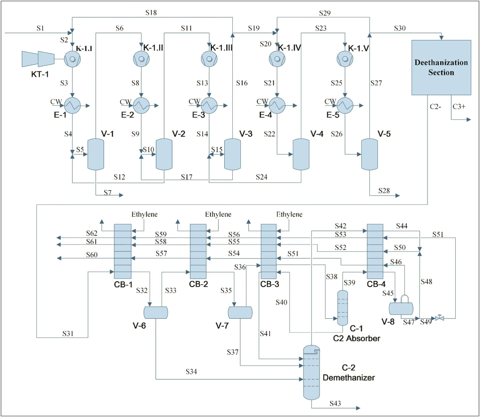
Fig.3.flow sheet of compression and refrigeration system.
4.Modeling and Analysis
Rigorous steady-state and dynamic models are developed to analyze start-up of ethylene plant compression and refrigeration systems.All steady-state and dynamic models are based on plant design data integration,process flow diagrams,piping and instrumentation diagrams,distributed control system historical data,compressor performance curves,equipment dimensions,heat capacity data and industrial expertise[17].
4.1.influence on compression system
By adjusting parameters in the steady-state models of cracking gas compressor,safe operating ranges of the compressor are obtained for different SWM compositions and compressor speeds.Fig.4 shows safe operating ranges for the same SWM composition at different compressor speeds and Fig.5 shows those for the same compressor speed and different SWM compositions.MaxFandMinFdenote the flow rates of compressor stonewall and surge limits.The area between them is considered as safe operating range of the cracking gas compressor.An excessive light component mole ratio(H2/CH4)will reduce the safe operating range significantly.To guarantee safe compressor operation,an upper lim It is provided For the ratio of lightcom ponents.Compressor speed, flow rate,and mixed gas components are related closely and influence each other.Hence,a compressor speed above 3970 r·min-1and a light component mole ratio below 0.4 are better.
4.2.influence on cracking system
The cracking gas compressor is a turbine compressor driven by SS.The compressor power upper limit is determined by SS production.SS can be produced by cracking furnaces or external SS devices,but external SS devices for start-up are uncommon in ethylene plants and additional equipment investment is required.SS production of cracking furnaces differs significantly under feeding or standby conditions.Table 1 gives the SS production of one cracking furnace under different operating conditions.A cracking furnace with 60 t naphtha feeding per hour can provide 80 t SS per hour in feeding mode but only 23-37 t SS per hour on standby.SS production can be increased by increasing the cracking furnace outlet temperature(COT)and feeding rate when the cracking furnaces are on standby.
In each cracking furnace in feeding mode,all cracking gas produced by the cracking furnace is sentto the flare system as an off-specification product before the refrigeration system reaches normal operating temperature conditions(-162.3°C).And externalSS device is needed if the SS demand is greater than the SS capacity of cracking furnaces,which means a large equipment investment.Ideally,the cracking gas compressor is started using mixed gas,and all mixed gas is cycled while the cracking furnaces on standby and no externalSS is needed.The selection of cracking furnace parameters on standby influences SS production significantly so that SS production and demand must be considered in the simulation.
The pressure required for system start-up is generally de fined by some specific devices.In this case study,to guarantee normal dryer operation and avoid water entering the refrigeration system,the compressor outlet pressure should be more than 24×105Pa.The compressor power is almost identical for the same SWM at the same speed.Fig.6 shows the compressor power and SS demand for the same SWM(H2/CH4mole ratio 0.3880)and different outlet pressure(surge limit pressure).When the system pressure requirementis reduced by equipment renovation,the SS demand could be reduced significantly.
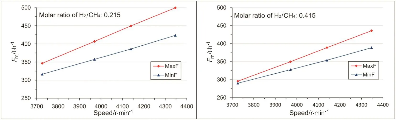
Fig.4.Safe compressor operating ranges for same SWM composition and different compressor speed.

Fig.5.Safe compressor operating ranges for same compressor speed and different SWM composition.

Table 1SS production under different cracking furnace operating conditions in the case study

Fig.6.Compressor power and SS demand for the same SWM(H2/CH4 at mole ratio 0.3880)and different outlet pressures(pressure of surge limit MaxP).
4.3.influence on refrigeration system
In MGR,the mixed gas flow rate at refrigeration system inlet is basically the same as that at compression system outlet.By combining the outlet pressure of the compression system,dynamic models of the refrigeration system are developed.The time for precooling the refrigeration system from-90 °C to-162.3 °C can be calculated.
Precooling time is one of the most important factors for total startup time and determines emission and energy losses by cracking furnaces(and external SS devices).Shorter precooling time is better.Fig.7 shows the precooling time with different compressor outlet pressures.The flow rate entering the fourth cold box can be higher if the light component ratio is higher or the compressor speed is lower.The throttling effect is better and the precooling time is shorter.From Fig.7,a mole ratio of H2/CH4greater than 0.35 and a compressor pressure lower than 24 bar reduce the precooling time.

Fig.7.Precooling time with different compressor outlet pressures at the same compressor speed and different inlet flow rates.
5.Selecting Start-up Scheme
The interrelations of parameters such as MG composition, flow rate,compressor speed,SS consumption and precooling time of refrigeration system are so complex that they cannot be summarized using simple function relations.Thus a graphical method based on simulation is used.
Fig.8 shows the start-up operation information,as shown in Table 2,giving the integration of key parameters in three systems(different stages of the cracking gas compressor)with differentMaxP,such as SWM composition, flow rate,compressor power and speed,SS production,safe operating range,and precooling time.
With Fig.8 and the method shown in Fig.1,suitable start-up scheme in this case is selected as follows.
(1)The maximum SS production is 320 t·h-1when all cracking furnaces are on standby.The upper limitof SS productionFssis fixed at 320 t·h-1.To satisfy pressure requirements of subsequent systems,the outlet pressure of the compressorPoutshould achieve at least 24×105Pa,soMaxPcan be set at 26×105Pa or 28×105Pa.
(2)LetMaxP=26×105Pa.From Fig.8(a),reasonable range formole ratio H2/CH4,rmole,is 0.38 with precooling timetof 6.1 h.The safe operating range of the compression system ΔFmis around 4.5 t·h-1,only 1.3%of the total flow rate of the first three stages of the compressorFm.It is an energy saving start-up scheme and the precooling time is acceptable,but the safe operating range is so small that it is difficult to ensure a safe start-up.
(3)LetMaxP=28×105Pa.Suitable range forrmoleis 0.35,the safe operating range ΔFmincreases to 11.5 t·h-1,which is equal to 3.2%ofFm,while the precooling timetis extended to 6.9 h.
(4)Increasing the upper limit of SS production to 345 t·h-1and keepingMaxPat 28×105Pa,the optimalrmoleis 0.420,which allows the precooling timetto be shortened to 5.0 h and the safe operating range ΔFmto be extended to 9.8 t·h-1,around 2.3%ofFm.However,the SS consumption of this start-up scheme exceeds the maximum SS capacity of cracking furnaces and external SS device is needed.
Above all,a most suitable start-up scheme is given as follows:
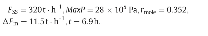
It can be seen that higher SS consumption increases the process energy loss,but yields shorter precooling time and safer operating range.The essence is to optimize key parameters based on simulation and obtain a start-up scheme with the minimum SS consumption satisfying operating requirements.
6.Conclusions
Selection of a suitable start-up scheme for compression and refrigeration system of ethylene plants is a multi-objective problem balancing the SS production,safe operating range and precooling time.Larger safe operating range and shorter precooling time are at the expense of higher SS consumption.Amethod to sel ectappropriate start-up scheme at the minimum SS consumption with sufficient safe operating range and acceptable precooling time is developed and demonstrated using industrial data.The study has significant value for guiding production and reducing emission during ethylene plant start-up.
Nomenclature
Fmmass flow rate of the first three stages of the cracking gas compressor
FSSmass flow rate of SS consumption
ΔFmsafe operating range(mass)of the first three stages of the cracking gas compressor
MaxPpressure of the compressor surge safe line at fixed compressor speed
Poutoutlet pressure of the cracking gas compressor
rmolemole ratio H2/CH4in mixed gas
Tprecooling time of the refrigeration system during MGR

Fig.8.Integration of start-up operation information.

Table 2Supplementary explanations of Fig.8
[1]Q.Xu,X.Yang,C.Liu,K.Li,H.H.Lou,J.L.Gossage,Chemical plant flare minimizationviaplant wide dynamic simulation,Ind.Eng.Chem.Res.48(2009)3505-3512.
[2]Q.Xu,K.Li,Dynamic simulation for chemical plantturnaround operation,Integrated Environmental Management Consortium Meeting,Houston,TX,2008,2008.
[3]G.Song,T.Qiu,J.Zhao,Flare minimization model for ethylene splitter system's shutdown,Ind.Eng.Chem.Res.52(2013)9180-9188.
[4]D.A.Max,S.T.Jones,Flareless ethylene plant,Hydrocarb.on Process.;(United States)62(1983).
[5]J.Fu,Q.Xu,Simultaneous study on energy consumption and emission generation for an ethylene plant under different start-up strategies,Comput.Chem.Eng.56(2013)68-79.
[6]G.Song,Y.Zhao,T.Qiu,G.Lu,J.Zhao,B.Chen,Recent progress in energy saving and emission reduction technologies in startup and shutdown processes of ethylene plant,J.Chem.Ind.Eng.(China)65(7)(2014)2696-2703.
[7]A.Singh,K.Li,H.H.Lou,J.R.Hopper,H.Golwala,S.Ghumare,T.Kelly,Flare minimisationviadynamic simulation,Int.J.Environ.Pollut.29(2007)19-29.
[8]L.Huang,New method for ethylene plant start-up with no emission loss:cycling start-up method,Pet.Chem.Ind.8(1988)007.
[9]A.Shaikh,C.Lee,Minimize flaring during ethylene plant startup,Hydrocarb.Process.74(1995).
[10]G.Liu,R.Xu,Nitrogen pre-cooling of ethylene plant cryogenic system before startup,Petrochem.Technol.Jinshan(1992)29-33.
[11]M.Khraisheh,F.Benyahia,N.Al.Ghanim,Flare reduction options and simulation for the Qatari oil and gas industry,Qatar Foundation Annual Research Forum Proceedings,Bloomsbury Qatar Foundation Journals:2011 2011,p.EVOS1.
[12]S.Gore,Plant Startup in CPIviaDynamic Simulation—Case Study,ProQuest,2005.
[13]R.O.Romero,Application of Dynamic Simulation During an Ethylene Plant Start-up,Lamar University-Beaumont,2007.
[14]X.Yang,Q.Xu,K.Li,C.D.Sagar,Dynamic simulation and optimization for the startup operation of an ethylene oxide plant,Ind.Eng.Chem.Res.49(2010)4360-4371.
[15]D.Chenevert,C.Harry,J.H.WALKER,B.Unterbrink,M.Cain,Flare minimization practices improve ole fins plant start-ups,shutdowns,Oil Gas J.103(2005)54-60.
[16]X.Yang,Q.Xu,C.Zhao,K.Li,H.H.Lou,Pressure-driven dynamic simulation for improving the performance of a multistage compression system during plant startup,Ind.Eng.Chem.Res.48(2009)9195-9203.
[17]Y.Zhao,J.Zhang,T.Qiu,J.Zhao,Q.Xu,Flare minimization during start-ups of an integrated cryogenic separation systemviadynamic simulation,Ind.Eng.Chem.Res.53(2014)1553-1562.
[18]S.Wang,Technology and Operation of Ethylene Plants,China Petrochemical Press Beijing,2009.
 Chinese Journal of Chemical Engineering2016年8期
- Chinese Journal of Chemical Engineering的其它文章
- Computational chemical engineering - Towards thorough understanding and precise application☆
- A review of control loop monitoring and diagnosis:Prospects of controller maintenance in big data era☆
- Experimental and numerical investigations of scale-up effects on the hydrodynamics of slurry bubble columns☆
- The heat transfer optimization of conical fin by shape modification
- The steady-state and dynamic simulation of cascade distillation system for the production of oxygen-18 isotope from water☆
- Experimental mass transfer coefficients in a pilot plant multistage column extractor