Numerical Analysis of Load-noise of a Highly-skewed Propeller behind Subm arine
ZHANG Ming-yu,LIN Rui-lin,WANG Yong-sheng,FU Jian,WEI Ying-san
(College of Marine Power Engineering,Naval University of Engineering,Wuhan 430033,China)
Numerical Analysis of Load-noise of a Highly-skewed Propeller behind Subm arine
ZHANG Ming-yu,LIN Rui-lin,WANG Yong-sheng,FU Jian,WEI Ying-san
(College of Marine Power Engineering,Naval University of Engineering,Wuhan 430033,China)
This investigation combined the Computational Fluid Dynamics(CFD)with Boundary Element Method(BEM)to predict the load noise of a highly-skewed propellers behind submarine(SUBOFF)with full appendages.The credibility of CFD was validated by comparing the results derived from steady simulation of the open water propeller with experiment data.The unsteady loading(dipole sound source)on blade surface was calculated by transient simulation of the same propeller fixed after submarine and then was transferred to the sound grid.The integration of the noise source was performed over the true blade surface,which was used to predict the propeller’s low-order blade frequency noise below 1 kHz.The BEM method was used to solve the FW-H equation to get the sound pressure directivity characteristics on the 3D spherical surface enclosed the propeller as well as two planes in the surface of the propeller disc and its perpendicular surface based on theory of acoustic fan source, total sound pressure level on the downstream axial measured points were also calculated.Study shows that the sound pressure directivity on both the propeller disc and its perpendicular plane presented as‘8’,but the directivity is not unique because of the existence of rotation and skew angle of the propeller.The 3D spherical field showed that the radiant surface in the direction of the propeller disc was smaller and radiated weaker than its perpendicular plane.The results of the typical points showed that the 1st order blade frequency SPL exceeded the high-order blade frequency SPL obviously, which accorded well with fact.A good consistency had gotten after comparing with the published literature and reasonable explanation was also given to the difference.Thus,this paper introduced a new method to measure the propeller noise behind submarine in the ship effectively.
submarine;highly-skewed propeller;CFD;BEM;Acoustic Fan Source
0 Introduction
Submarine has been welcomed by navies of all ages because of its good concealment,aggressive characteristics.Submarine underwater radiated noise is one of the key factors affecting the submarine concealment in nature,which includes mechanical vibration noise,propeller noise,fluid induced noise.Propeller noise is the main source of noise,which was first foundby underwater monitor during World War II[1].Propeller cavitation noise is mainly concentrated in the high frequency band and has got improved synchronously under the medium-low speed.However,no-cavitation noise concentrated in the low frequency band performed very obviously.Currently,people began to pay attention to study this kind of noise.Both the submarine’s velocity and the propeller’s rotating speed are small,thus propeller no-cavitation noise brings greater harm.Sound field radiated by propeller mainly consists of the dipole sound noise(load noise)generated by unsteady loads[2-3]in the non-uniform flow without cavitation, so the study on no-cavitation noise of propeller fixed after submarine has a very important significance.
Zhu,Tang et al[4]had combined the unsteady lifting surface theory and acoustic methods to calculate the low-frequency discrete spectrum-line of non-cavitation noise of different propeller while effect of propellers’geometry parameters(such as propeller diameter,pitch, number of leaves,skewed,arch)to sound pressure level brought in consideration.Zhu and Wu[5]researched a propeller’s load noise characteristics based on unsteady lifting surface theory method and Goldstein theory,a brief introduction to the theoretical results and the numerical analysis method was illuminated.Seol et al[2]made a further exploration on the calculation method for calculating propeller underwater no-cavitation noise of far fields by combining the surface element method and boundary element.Analysis of unsteady propeller forces changing over time was made out and then input the forces to FW-H equation to predict the far-field sound radiation of propeller via plane element method in Ref.[3].Pantle et al[6]calculated the time-domain solution of unsteady flow field of propeller using large eddy simulation and computed its radiated noise under no-cavitation conditions through FW-H integral model.Refs. [7-8]introduced hybrid calculation method,the mutual coupling of the flow field and the sound field using the drop-coupling treatment.Sound source was the unsteady pressure resulting from the large eddy simulation,propeller noise spectrum was derived from the FW-H integral model.
This paper used large eddy simulations(LES)on the unsteady three-dimensional numerical calculations of‘submarine+propeller’through software CFX and used the boundary element method to calculate the frequency-domain load noise of a highly skewed propeller in the non-uniform flow behind the submarine based on theory for acoustic fan source,its noise distribution was analyzed and the results of the same feature points were taken out,which coincided better with the Ref.[9],the differences were also reasonably explained,studies show that Acoustic Fan Source is a new way to predict propeller noise effectively.
1 Theoretic analysis
1.1 Equation and tools
In 1969,Ffowcs Williams and Hawkings extended Curle equation to bring the impact of the moving solid boundary into consideration via generalized function,which considered prob-lems of objects moving in the fluid,such as propeller’s non-cavitation noise at work,which made the FW-H equation used more commonly[10]and laid the theoretical foundation of flow noise.

where Maris the projection of Mach number on the observer direction,S(ζ)is the acreage of moving solid.The first item on the right of equation is thickness noise,which is the noise resulting from the drain caused by blade rotation.The second term is the dipole sound source which is also known as the load noise,and is brought in by the pulse on a solid wall,the pulse can be considered only generated by fluid.Load noise plays a major role at low Mach number, this study considered the dipole sound source as the main propeller noise.The third term on the right of above equation is the quadrupole sound source generated by turbulent fluctuations in the fluid and the interaction of shear layers,which is prominent in the high Marand can be ignored when the value is low[11].
1.2 Theory for Acoustic Fan Source
There is only rotor with no stator for propeller;the expression for this acoustic field for different fan configurations is summarized as below.
Axial and tangential contributions of the radiated pressure at frequency mBΩ:

where m is the harmonic number,B is the number of rotor blades,Ω is the rotation speed,R is the distance from the observer,c0is the speed of sounds,is the Fourier series of the total force on a compact blade segment,M is the rotational Mach number,θ,φ and γ are defined in Fig.1,γ is the number of stator vanes.
Radial contribution:
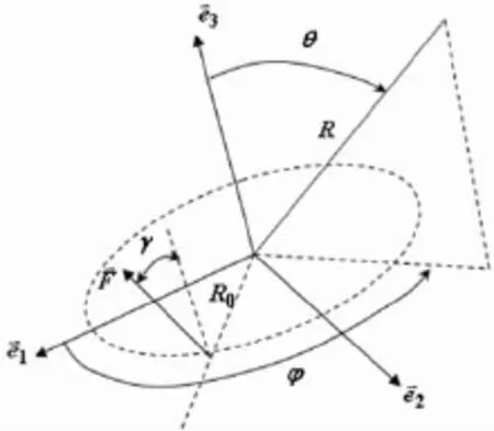
Fig.1 Acoustic fan source
In the above expressions,the pressure field is computed from the loading force on a reference rotor blade.This force can be computed from the pressure fluctuations in time domain obtained from a CFD(computational fluid dynamic)computation.The computation of this force is done in a new analysis case.
The resulting loading force is applied at one point of the blade.The representation of thefan by a single fan source is a good approximation when the size of the blades is small compared to the wavelength(compact source approximation).When the size of the blade is very large and the fan cannot be considered as a compact source,the blade can be subdivided into a set of segments where each segment can be replaced by an equivalent source.
The computation of centers of gravity of segments base nodes is expressed as follows:

where xikis the k th coordinate of the i th node.The forces acting on the different segments are calculated by using the following equations:

k th component of the total force on j th segment at the i th time.Pimis the pressure at the i th time step at m th node,nodal_area_vectormkis the k th component of the nodal area vector at m th node.
2 Com puting model and numerical sim ulation
This paper used RANs method to carry out CFD calculations.Steady simulation of flow field of open water propeller was executed through solving the control equations based on SST turbulence model.Firstly,SST model combines the advantages of both k-ε model and k-ω model,k-ε model has good convergence for simulating flow in the near wall region while k-ω model has higher computational efficiency where region turbulence is fully developed[12].The three-dimensional unsteady calculations using large eddy(LES)method of the highly skewed propeller fixed behind the submarine was developed after verifying the credibility of numerical calculation,the large eddy simulation’s accuracy and resource requirements are just between DNS and RANS,the application of large-eddy simulation method has gradually expanded along with a continuous improvement of LES theory and the gradual accumulation of experience in application.We can get the propeller’s frequency-domain sound field based on theory for acoustic fan source after calculated the acoustic dipole distribution on propeller surface.
2.1 Steady state calculation and verification of open water propeller
Using software ICEM to mesh the 3D geometry of highly skewed propeller with 7 blades drew out by software Ug.The total grid number was 1 360 000,which was specifically shown in Fig.2,settings of the boundary conditions were shown in Fig.3,the number of computational domain grids was 2 100 000 while grid thickness of the first layer near the surface is 0.1 mm,the value of y+satisfied the requirement of the boundary layer turbulence required for simulation.6 working conditions at the speed 20 r/s with J=0.4~0.9 were calculated and axialthrust T and torque Q of propeller were derived through integration on the wall,which were converted into thrust coefficient,torque coefficient and efficiency as follows:
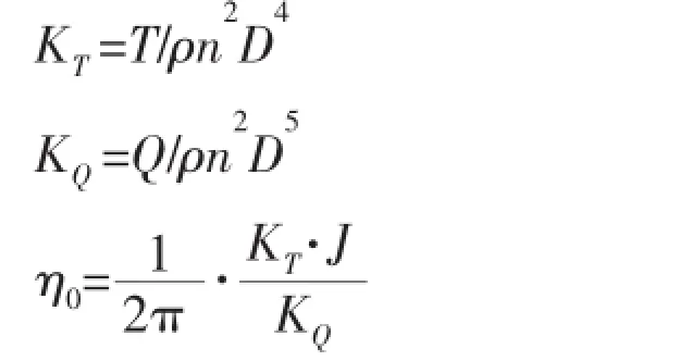
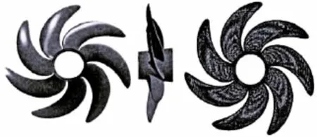
Fig.2 Geometry and structured grid of the highly skewed propeller
where D is the propeller diameter,n is the rotational speed,J is the feed ratio.
Values of thrust coefficient and torque coefficient at 20 r/s with J=0.4~0.9 were made out and curves of both the CFD values and experimental data were shown in Fig.4,the CFD values consisted with the experimental well and the error was less than 3%.
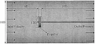
Fig.3 Computational domain and boundary conditions
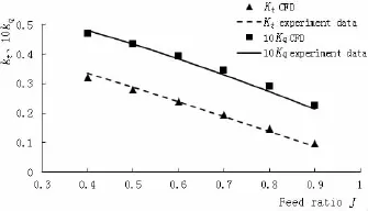
Fig.4 Compared with experimental data
2.2 Unsteady three-dimensional numerical simulation of the propeller fixed behind submarine SUBOFF
The length of SUBOFF is 4.356 m,the maximum diameter is 0.508 m,podium length is 0.368 m,four empennages are arranged symmetrically in NACA0020 airfoil.The distance from the bow to propeller plane is 4.26 m.The distance on inflow direction takes a captain while twice on the out flow direction for the entire flow field computational domain whose diameter decuple the maximum boat diameter.All the mesh is hexahedral and the total number is 20 100 000.The velocity of flow was 6 kt,the outlet was set as atmospheric pressure,rotational speed of propeller was 750 r/min,steady-state time step take 0.012 s based on expression 30/(nπ),n is the rotational speed rpm.Transient calculation started on the result of steadystate.The higher sampling frequency obtained higher time resolving power of the data,pulsation amplitude may be underestimated if the sampling frequency is too low[13].This paper takes every time step from rotation time of 1°synthetically,1/(6n)=0.000 022 s.Computational domain and boundary conditions of‘boat+ propeller’were shown in Fig.5,here L is captain,D sub is the maximum diameter of the hull,and the stream lines were shown in Fig.6.

Fig.5‘Boat+propeller’boundary conditions and computational domain
3 Sound field calculation of the highly skewed propeller behind submarine
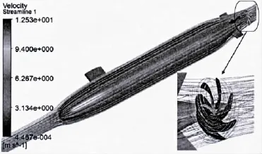
Fig.6 Streamline
3.1 Data transfer
Extracting the propeller surface pressure after the above three-dimensional unsteady calculation was convergent and mapped it onto the sound grid through distance-weighted method. This paper imported the pressure datum of 360 time steps,namely 1 circuit of propeller.λ=c/ f,f≤1 kHz,the wavelength is at least 1.5 m so that there were enough units to describe the sound field within each wavelength even though the size of acoustic grid cell was a little larger.Acoustic Fan Source just takes one blade to calculate sound field and then describe the work of the propeller blades by defining the number of blades and rotational speed.The sound pressure information of a skewed propeller blades to a corresponding sound field grid was transferred by nodes scale 4:1,grids and pressure distribution were shown in Figs.7 and 8.
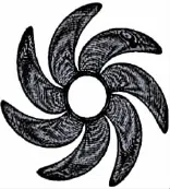
Fig.7 Fluid mesh

sound grid
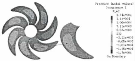
Fig.8 Pressure extracted from CFD mapped pressure
3.2 Acoustic Fan Source settings and number verification of dipole segments
Dividing the blade into segments after defining the rotating coordinate, each block will be treated as an equivalent dipole sound source.The results of 13 and 34 segments under 1BPF (Blade Passing Frequency)showed that the sound directivity overlapped substantially on both propeller disk and its vertical surface,which verified theindependence of the number of dipole segments.The segments and corresponding results of sound directivity were shown in Fig.9.Rotational speed of propeller is 12.5 r/s,the number of blades is 7,the time domain information is transformed into the frequency domain though Fast Fourier Transform.
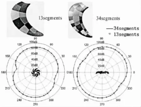
Fig.9 Segments and results
4 Sound field analyses
Two panel sound fields,which were on propeller disc and the axial longitudinal section of the highly skewed propeller,and a spherical sound field were established respectively,all of whose center were the geometric center of the propeller and all their diameters were the 10 times of the propeller diameter.This paper analyzed all the sound fields in detail based on fact and corresponding theory.Results of the same feature point with Ref.[9]were calculated and consisted well with Ref.[9].
4.1 Sound directivity analysis
Sound directivity is an important item on analyzing the characterization of sound field, this paper analyzed two panel sound field respectively on propeller disc and the axial longitudinal section of the highly skewed propeller.The sound pressure level(SPL)in blade passing frequency and its harmonics were shown in Figs.10 and 11.As can be seen,both the surface sound fields can be observed two strong and weak radiation directions in the shape of‘8’, which was determined by the dipole sound source,but the directivity is not unique because of the existence of rotation and skew angle of propeller.We can also see that the SPL is slightly lower on propeller disc than that of the axial longitudinal section.

Fig.11 Axial longitudinal section of the sound field directivity
4.2 Spherical field analysis
Analysis to the sound field distribution of the spherical field at different frequencies was shown in Fig.12.The SPL is the highest in axial direction of the propeller and gradually decreases along with the increase of axial angle.Sound source area perpendicular to the propagation direction is smaller in the radial direction,which is contrary to the axial direction.So the propeller load noise radiates strongly in the axial direction and weakly on the radial direction,which is consistent with the mechanism of the propeller load noise.

Fig.12 SPL distributions on spherical field
4.3 Analysis of feature points
Three feature points were arranged on a circle,whose distance to the geometric center of the propeller is 10R(R is the radius of the propeller).Their specific position and spectrogram were shown in Fig.13,the point 3 is in the axial direction of propeller,which is the same with the feature point of Ref.[9]. The sound spectrum of feature points also incarnated that SPL is the highest in axial direction of the propeller.
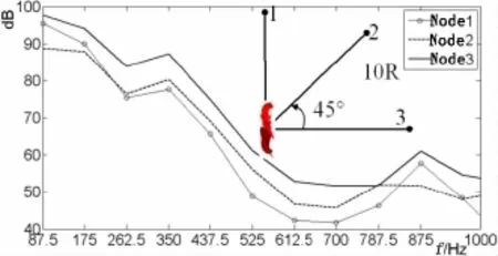
Fig.13 Feature points’arrangement and sound pressure spectrum


Tab.1 Results contrast of feature point 3
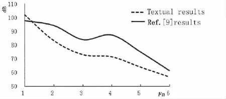
Fig.14 Results of feature point3
5 Conclusions
The credibility of CFD was validated firstly by comparing the results derived from steady simulation of the open water propeller with experiment data.The unsteady loading(dipole source)on blade surface was calculated by transient simulation of the same propeller fixed after submarine and then was transferred to the acoustical mesh nodes.The BEM method based on Acoustic Fan Source theory was used to solve the FW-H equation to get the sound directivity characteristics on three sound fields.Studies show that:
(1)Both the surface sound fields can be observed by two strong and two weak radiation directions in the shape of 8,which are determined by the dipole sound source,but the directivity is not unique because of the existence of rotation and skew angle of propeller.We can alsosee that the SPL is slightly lower on propeller disc than that of the axial longitudinal section.
(2)Sound source area perpendicular to the propagation direction is smaller in the radial direction,which is contrary to the axial direction,so the propeller load noise radiates strongly in the axial direction and weakly in radial direction,which is consistent with the mechanism of the propeller load noise.
(3)The results of the feature points showed that the SPL value at 1st order blade frequency exceeded SPL value at high-order blade frequency obviously,The SPL value of feature point 3 below 1 kHz is 99.7 dB under J=0.88,rotational speed=12.5 r/s,which consisted well with Ref.[9].
Studies show that Acoustic Fan Source is a new way of predicting propeller noise effectively.
[1]Zhong Xiaonan.Propeller noise of vessel[M].Shanghai:Shanghai Jiao Tong University Press,2011:23-27.
[2]Seol H,Jung B,Suh J C.Prediction of non-cavitation underwater propeller noise[J].Journal of Sound and Vibration 2002, 257(1):131-156.
[3]Seol H,Suh J C,Lee S.Development of hybrid method for the prediction of underwater propeller noise[J].Journal of Sound and Vibration,2005,288:345-360.
[4]Zhu Xiqing,Tang Denghai,Sun Hongxing.Study of The low-frequency propeller noise[J].Journal of Ship Mechanics, 2000,4(1):50-55.
[5]Zhu Xiqing,Wu Wusheng.Prediction of marine propeller loading noise[J].Acta Acustic,1999,24(3):259-268.
[6]Pantle I,Magagnato F,Gabi M.Numerical noise prediction in fluid machinery[J].Journal of Thermal Science,2005,14 (3):230-235.
[7]Kato C,Yamade Y,Wang H.Numerical prediction of sound generated from flows with a low mach number[J].Computers&Fluids,2007,36:53-68.
[8]Wang M,Freund J B,Lele S K.Computation prediction of flow-generated sound[R].New York:Annual Review of Fluid Mech,2006,38:483-512.
[9]Yang Qiongfang,Wang Yongsheng,Zeng Wende.Calculation of highly-skewed propeller’s load noise using BEM numerical acoustics method in frequency domain[J].Acta Armamentarll,2011,32(9):1118-1125.
[10]Ffowcs W J E,Hawkinns D L.Sound generation by turbulence and surfaces in arbitrary motion[C]//Proc.Rov.Soc.London:Roy.Soc.1969,264A:321-342.
[11]ANSYS CFX User’s Guide.Aerodynamic noise analysis[K].ANSYS Inc,2006.
[12]Jin Shuanbao,Wang yongsheng,Yang Qiongfang.Integrative design of waterjet axial pump based on numerical experimentation[J].Shipbuilding of China,2010,51(3):39-45.
[13]Shi Weidong,Yao Jie,Zhang Desheng.Influence of sampling frequency and time on pressure fluctuation characteristics of axial-flow pump[J].Journal of Drainage and Irrigation Machinery Engineering,2013,31(3):190-195.
[14]Ye Jinm ing,Xiong Ying,Gao Xiaopeng.Prediction method of low-order blade frequency noise of non-cavitation propeller in time domain[J].Journal of Harbin Engineering University,2013,34(1):1-6.
艇后大侧斜螺旋桨负载噪声数值分析
张明宇,林瑞霖,王永生,付建,魏应三
(海军工程大学动力工程学院,武汉430033)
为研究艇后非均匀流场中大侧斜螺旋桨无空泡负载噪声的分布规律,文章采用“CFD+BEM”法,以SUBOFF潜艇后某大侧斜桨为研究对象,首先稳态计算均匀进流下螺旋桨敞水特性,模拟系数值与实验误差在3%以内,验证了CFD数值计算的可信性。然后采用大涡(LES)模拟,对“艇+桨”进行三维非定常数值模拟,计算得到桨表面声偶极子数据后,通过距离加权平均法映射到声网格节点上,将噪声源直接分布在桨叶表面上进行积分来预报螺旋桨的低频线谱噪声。采用边界元法基于扇声源理论通过FW-H声类比方程分别在1 kHz以内对桨盘面、轴向纵剖面及10倍桨半径球场的噪声进行频域求解。研究表明:桨盘面和轴向纵剖面上声指向均呈8字形,但受螺旋桨自身旋转及大侧斜的存在,指向性不唯一;球场声场显示,轴向声辐射面较大,声辐射强,径向辐射面小且辐射较弱;特征点的计算结果显示,高阶叶频声压级明显比一阶叶频低,这与物理现象相符,将特征点处结果与已发表文献进行对比,吻合性良好,并对存在的差异作出了合理的物理解释。该文为螺旋桨噪声预报介绍了一种可行的新方法。
潜艇;大侧斜螺旋桨;计算流体力学;边界元法;扇声源理论
U664.33
A
国家自然科学基金资助项目(51009144)
张明宇(1989-),男,海军工程大学动力工程学院博士研究生,E-mail:yijianmingyu@163.com;林瑞霖(1955-),男,博士,海军工程大学动力工程学院教授,博士生导师;王永生(1955-),男,海军工程大学动力工程学院教授,博士生导师;付建(1985-),男,海军工程大学动力工程学院博士;魏应三(1984-),男,海军工程大学动力工程学院讲师。
U664.33
A
10.3969/j.issn.1007-7294.2016.09.010
1007-7294(2016)09-1190-11
Received date:2016-01-17
Foundation item:Supported by National Nature Science Foundation of China(51009144)
Biography:Zhang Ming-yu(1989-),male,Ph.D.candidate,E-mail:yijianmingyu@163.com; LIN Rui-lin(1957-),male,professor/tutor.
- 船舶力学的其它文章
- Research on Influence of Rudder-Bulb-Fin Parameters on Hydrodynam ic Performance of Tw isted Rudder
- Numerical Study on Hydrodynam ics of Ships in Oblique M otion with M ulti-Degree of Freedom
- Study on Vortex-induced M otion Characteristics of Variable Cross Section M ulti-column of a New Type of Deep Draft FDPSO
- Slamm ing Study of W edge and Bow-flared Sections
- Dynam ic Pre-ultim ate Strength Evaluation of Containership based on a 2D M odified Hydroelasticity M ethod in Extrem e W aves
- Application of Inertia Relief in the Prediction of W elding Deformation for Large Complex Structures

