Slamm ing Study of W edge and Bow-flared Sections
YU Peng-yao,REN Hui-long,LI Hui,WANG Song,SUN Li-ming
(1.Transportation Equipment and Ocean Engineering College,Dalian Maritime University,Dalian 116026,China; 2.College of Shipbuilding Engineering,Harbin Engineering University,Harbin 150001,China)
Slamm ing Study of W edge and Bow-flared Sections
YU Peng-yao1,REN Hui-long2,LI Hui2,WANG Song2,SUN Li-ming2
(1.Transportation Equipment and Ocean Engineering College,Dalian Maritime University,Dalian 116026,China; 2.College of Shipbuilding Engineering,Harbin Engineering University,Harbin 150001,China)
Through the analysis of the Modified Logvinovich Model(MLM),a semi-analytical model which is more suitable to the wedge section with a large deadrise angle is proposed.With the study of the bow-flared slamming by the computational fluid dynamics(CFD)method,the irrationality of the existing rules is pointed out and the semi-analytical method is expanded to predict the bow-flared maximum pressure coefficient.During the slamming study of the wedge and bow-flared section,the results of the semi-analytical method and the CFD method are compared,which verifies the availability of the semi-analytical method.
analytical method;CFD method;hydrodynamic impact;slamming
0 Introduction
During sailing in the rough seas,the ship often suffers serious slamming loads.Considering the complexity of this problem,the wedge section and bow-flared section are usually used to study slamming problems.The earliest theory analysis on slamming problems was begun by von Karman[1],who was concerned with seaplane landing problems.Based on the flat disc assumption,Wagner[2]took into account the fluid surface rise and solved the slamming problem of a blunt section.To correct the unbounded velocities and unbounded pressure of the contact region edge in the original Wagner model,many methods were proposed.Armand&Cointe[3], Howison[4],et al and Zhao&Faltinsen[5]studied this problem with the help of the matched asymptotic expansions method.Logvinovich[6]added some extra terms to the distribution of the velocity potential which made the flow velocity at the edge of the contact region bounded.Korobkin[7]gave a rational derivation of the Logvinovich model and proposed the modified Logvinovich model(MLM).Tassin[8]assessed and compared the results of several analytical models. For the flow separation of the finite width wedge section,Duan[9]introduced a fictitious section to expand the application of MLM.
With the development of computing technology and capability,many CFD techniques are adopted to solve complex hydrodynamic impact problems.Zhao&Faltinsen[5]used a nonlinear boundary element(NBE)method to study the water entry of a wedge section at a constant velocity and the calculation results were verified by the comparison of the similarity solution. Sun&Faltinsen[10]solved the water entry of a bow-flared section by using a NBE method and compared their results with experiment data.Dealing with slamming problems,Aquelet[11]studied the damping effects of the Arbitrary Lagrangian Eulerian(ALE)method.With the help of the commercial explicit FE-code LS-DYNA which contains the ALE method,Stenius[12]et al, Luo[13]et al and Shan&Guedes Soares[14]predicted slamming loads on two-dimensional sections.The smoothed particle hydrodynamics(SPH)method and the volume-of-fluid(VOF) technique were also used to simulate the water entry of ship sections separately by Veen& Gourlay[15]and Seng[16]et al.
During the derivation of the analytical model,the impacting section is usually assumed as a blunt section and some simplifications are unavoidable introduced,so the results of the analytical model are sometimes irrational.Compared with the analytical model,the CFD methods usually can give exact results;however they require large computational resources,which prohibit their use for engineering applications.Taking into account the deficiencies of the analytical method and the CFD method,a semi-analytical model is proposed to solve the slamming problem of wedge and bow-flared sections in this paper and the ALE method of LS-DYNA is also adopted to validate the semi-analytical model.
1 Description of the sem i-analytical model
1.1 Modified Logvinovich Model
For the Modified Logvinovich Model(MLM),when the wedge section enters the fluid(see Fig.1)at a constant velocity,the distribution of pressure in the contact region is given as

where ρ is the fluid density,V is the velocity of the impacting section,is the half-wide of the contact surface,is the time derivative ofand β is the deadrise angle of the wedge section.is determined with the help of the Wagner condition,which can be written as

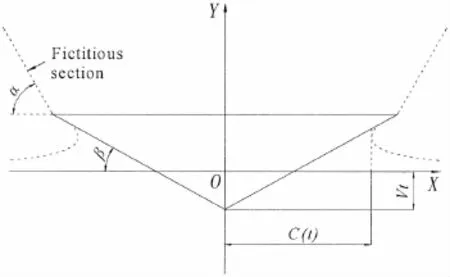
Fig.1 The water entry of a wedge section
where f(x)is the function to describe the section shape.
In the case of the wedge,the equation(2)can be expressed in the form

1.2 Introduction of the fluid surface rise coefficient
If the fluid surface rise is ignored during the impacting section entering the fluid,the halfwide of the contact surface should be given as

The fluid surface rise coefficient is defined as the ratio of the half-wide of the contact surface when the fluid surface rise is considered to that when the fluid surface rise is not considered.After comparison the equation(4)with the equation(3),the fluid surface rise coefficient of MLM is obtained:

where cvis the fluid surface rise coefficient.
MLM is applicable to the blunt section.For the wedge with a large deadrise angle,whether the fluid surface rise coefficient is still equal toneeds to be discussed.So the Wagner condition and the half-wide of the contact surface can be expressed in the following forms in advance:
1.3 Correction of the negation pressure
For the equation(1),under the influence ofthe pressure of the contact re-


It can be seen that with the increase of β,the value of τ decreases which shows the region of negation pressure increases.During the actual slamming process that the rigid wedge section enters the fluid at a constant velocity,the pressure of the contact region should always be positive.To correct the unreasonable negative pressure,the pressure of the region-a(t)<x<a(t)is mapped to the region-c(t)<x<c(t)by the ratio τ.So the distribution of pressure in the contact region is given as

It can be seen that the pressure is equal to zero when x is equal to c and the unreasonable negative pressure is avoided.
1.4 Truncation of the pressure distribution
Fig.2 is the comparison of the pressure distribution between MLM solution and self-similarity solution.The horizontal axis represents the dimensionless vertical coordinates of the wedge surface and the vertical axis represents the dimensionless pressure of the wedge surface.The result of similarity solution is taken from the Ref.[5].As shown in Fig.2,when the deadrise angle is small,the solutions of the two methods are very close;however,the deviation of the two methods increases with the increase of the deadrise angle.According to the maximum pressure coefficient CPmaxof self-similarity solution,the pressure distribution of MLM solution is truncated to modify its irrationality for the large deadrise angle.With the maximum pressure coefficient of self-similarity solution,the fitting formula for the calculation of CPmaxcan be given as

where the unit of β is degree.

Fig.2 The comparison of the pressure distribution between MLM solution and self-similarity solution
So the truncated pressure distribution in the contact region is given as:

1.5 Flow separation
As shown in Fig.1,a fictitious section is introduced to deal with the flow separation.On the assumption that the fluid rises along the fictitious section when the flow separation happens,the section shape function which considers the fictitious section is given as

where b is the half-wide of the wedge section and α is the angle between the fictitious section and the horizontal direction.
Get the time derivative of both sides of equation(6),then we obtain


Introduce a parameter θsthat satisfied the equation·sinθs=L cos β,so equation(14) can be transformed into the following expression:

When the flow separation happens,should be calculated by equation(17).is the time integral ofand the pressure distribution expression in the contact region is the same as the equations(11)and(12).
For the comparison with the results of LS-DYNA,the average pressure of the wedge surface is given as

When c(t)>b,the flow separation has happened.
2 Calculation of the wedge section
2.1 Discussion of the fluid surface rise coefficient
With the help of commercial software LS-DYNA,slamming cases that wedge sections of different deadrise angles entering the fluid at different velocities are simulated.The average pressure shape of the wedge surface is shown in Fig. 3.At the initial time,the lowest point of the wedge section is just located at the initial fluid surface. Before the peak time,the relationship between the average pressure and the time is nearly a linear function.Define the time when the average pressure reaches the peak as tmax.
For wedge sections of different deadrise angles,the length of bevel edge L is always equal to 0.54 m and the half-wide of the wedge section is equal to L cos β.When the wedge section of 20 degree deadrise angle enters the water at the velocity of 15 m/s,the water surface elevation and the pressure contour at the time tmaxare shown in Fig.4.
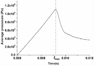
Fig.3 The average pressure shape of the wedge surface
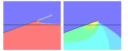
Fig.4 The water surface elevation and the pressure contour at the time tmax
It can be seen that the root of the jet flow just reaches the edge of the wedge section at the time tmaxand the pressure in the jet flow is equal to the atmospheric pressure which can be ignored.Then,the averageof the simulation result before the flow separation can be achieved:

For the wedge section entering the fluid at a constant velocity,is a constant beforethe flow separation in the semi-analytical model.So theis approximately equal toConsidering the equations(7)and(19),the fluid surface rise coefficient of simulation calculation is given as

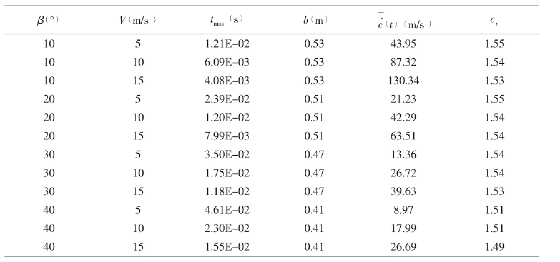
Tab.1 The simulation results of different im pacting cases
As shown in Tab.1,the fluid surface rise coefficients of different impacting cases are very close and approximately equal toConsidering that the influence of the impacting velocity and the deadrise angle on the fluid surface rise coefficient are little,cvis set as 1.54 in the following calculation.
2.2 Comparison of the average pressure
Several impacting cases that different wedge sections entering the fluid at the velocity of 15 m/s are calculated by both the semi-analytical method and the ALE method of LS-DYNA. Through many tests of the semi-analytical method,α of 10°,20°,30°and 40°wedge sections are separately set as 40°,40°,45°and 50°.The comparison of the average pressure is shownin Fig.5,in which the horizontal axis represents the dimensionless time and the vertical axis represents the dimensionless average pressure of the wedge surface.It can be seen that the results of two methods are very close and the semi-analytical method is available to predict the average pressure of wedge sections.
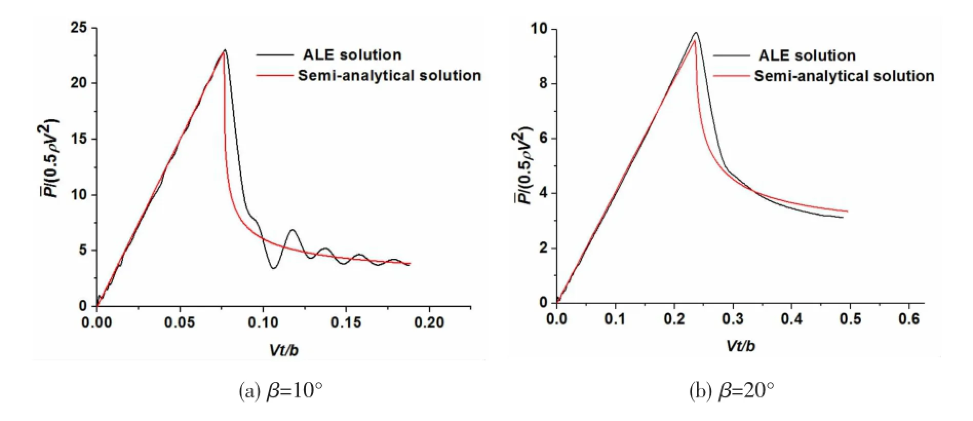
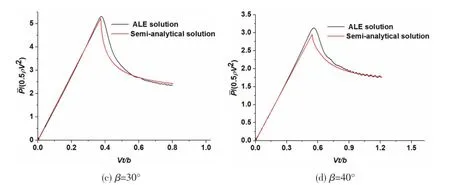
Fig.5 The comparison of the semi-analytical method and the ALE method
3 Calculation of the bow-flared section
3.1 Description of the bow-flared section
A typical bow-flared section is shown in Fig.6.The variation of the deadrise angle in the bow-flared region is shown in Fig.7.Twelve points are selected to study the influence of the deadrise angle variation on the maximum pressure coefficient and their information are listed in Tab.2.
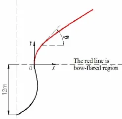
Fig.6 A typical bow-flared section
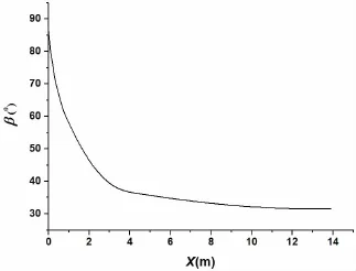
Fig.7 The variation of the deadrise angle in the bow-flared region

Tab.2 The information of the calculation points

Continue Tab.2
3.2 Comparison between the ALE method and the rules
With the help of commercial software LS-DYNA,slamming cases that the bow-flared section entering the fluid at the different velocities are simulated.The maximum pressure coefficient is achieved by using the maximum slamming pressure:

where Pmaxis the maximum slamming pressure.
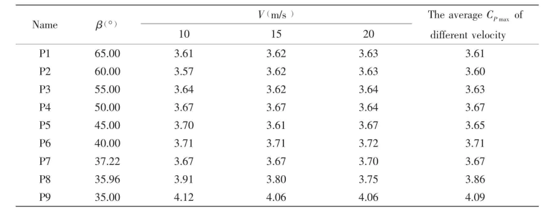
Tab.3 The maximum pressure coefficient of the bow-flared section
As shown in Tab.3,the influence of impacting velocity on the maximum pressure coefficient is very little and the average maximum pressure coefficient of different velocities is used to study the influence of the deadrise angle variation on the maximum pressure coefficient. The comparison between the ALE method and the rules is shown in Fig.8.Rule 1 and Rule 2 are seen in the references[17-18].It can be seen that the difference between the ALE method and the rules is very large.When the deadrise angle is greater than 37°,the maximum pressure coefficient of the rules decreases with the increase of the deadrise angle;however,the maximum pressure coefficient of the ALE method changes little.The reason for this is that the high slamming pressure of the small deadrise angle location would spread to the big deadrise angle location,so the maximum pressure of the big deadrise angle does not happen at the time when the location just touches the fluid surface and under the influence of pressure spread, the pressure of the big deadrise angle location would increase gradually.This phenomenon is also verified by the pressure results of the ALE method,which is shown in Fig.9;however,the pressure spread is not considered in the rules.
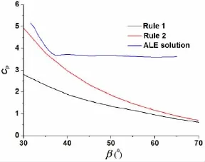
Fig.8 The comparison between the ALE method and the rules
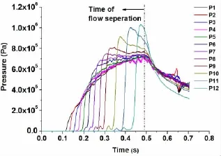
Fig.9 The pressure results of the ALE method
3.3 Semi-analytical method for the prediction of CPmax
The parameters in the semi-analytical method to predict the bow-flared maximum coefficient are shown in Fig.10.s is the intersection of the fluid surface and the bow-flared curve, β is the deadrise angle of this location,c is the half-wide of the contact region,p is the point on the bow-flared curve,and q is the point on the wedge section which has the same X coordinate as point p.To predict the pressure coefficient of the bow-flared curve when the fluid surface reaches the point s,a wedge section of the deadrise angle β is introduced.The pressure coefficient of the bow-flared curve can be approximately determined by the pressure coefficient of the wedge section.For example,the pressure coefficient of point p can be considered equal to that of point q on the wedge surface.

Fig.10 The schematic diagram for the application of the semi-analytical method
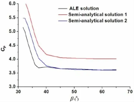
Fig.11 The comparison between the ALE method and the semi-analytical method
To the simulation result of the ALE method,the maximum pressure coefficients of different locations appear before the flow separation.So we just need the pressure coefficient distribution of the wedge section before the flow separation.By virtue of equations(7)and(12),the pressure coefficient distribution of the semi-analytical method is given as

It is obvious to see that the pressure coefficient distribution on the wedge is independent of the impacting velocity.Then,the bow-flared pressure coefficient distribution of the different contact region can be obtained,so is the maximum bow-flared pressure coefficient of different locations,which is named as‘Semi-analytical solution 1’in Fig.11.It can be seen that the trends of the‘ALE solution’and the‘Semi-analytical solution 1’are the same;however,the maximum coefficient of the‘Semi-analytical solution 1’is a little greater than that of the‘ALE solution’.The reason for this may be that the high slamming pressure of the small deadrise angle location would increase the pressure of the big deadrise angle location and conversely,the low pressure of the big deadrise angle location would decrease the pressure of the small deadrise angle location.The original semi-analytical method does not consider the influence of the big deadrise angle location on the small deadrise angle location.A reduction factor kris introduced to improve the solution of original semi-analytical method.Through multiplying krby the original solution,the modified solution is obtained,which is named as‘Semi-analytical solution 2’.How to determine the value of krshould be further studied and when kris set as 0.9,the improved result is shown in Fig.11.
4 Conclusions
The semi-analytical method and the numerical simulation method are involved into dealing with the slamming problem in this paper.During the process of the study on wedge and bow-flared sections entering into the fluid,several findings are summarized below.
(1)By correcting the negation pressure and the pressure distribution of the Modified Logvinovich Model,a more reasonable semi-analytical model is proposed to deal with the wedge section with a large deadrise angle.
(2)With the help of the ALE method,it is found that the variation of the deadrise angle and impacting velocity has little influence on the fluid surface rise coefficient.Through the comparison between the ALE method and the semi-analytical method,the availability of the semi-analytical method to predict the average pressure of the wedge section is verified.
(3)By comparison the bow-flared maximum pressure coefficient of the ALE method with that of the rules,the irrationality of the rules is pointed out.Through expanding the application of the semi-analytical method,a fast and reasonable method to predict the bow-flared maximum pressure coefficient is given.
[1]Von Karman T.The impact on seaplane floats during landing[R].NACA Technical note No.321,1929.
[2]Wagner H.Landing of seaplanes[R].NACA Technical Memorandum No.622,1931.
[3]Armand J L,Cointe R.Hydrodynamic impact analysis of a cylinder[J].Journal of Offshore Mechanics and Arctic Engineering, 1987,109(3):237-243.
[4]Howison S,Ockendon J,Wilson S.Incompressible water-entry problems at small deadrise angles[J].J Fluid Mech,1991, 222(1):215-230.
[5]Zhao R,Faltinsen O.Water entry of two-dimensional bodies[J].Journal of Fluid Mechanics,1993,246:593-612.
[6]Logvinovich G.Hydrodynam ics of flows with free boundaries[J].Naukova Dumka,1969.
[7]Korobkin A.Analytical models of water impact[J].European Journal of Applied Mathematics,2004,15(6):821-838.
[8]Tassin A,Jacques N,El Malki Alaoui A,et al.Assessment and comparison of several analytical models of water impact [J].The International Journal of Multiphysics,2010,4(2):125-140.
[9]Duan W,Zhu X,Ni Y,et al.Constant velocity water entry of finite wedge section with flow separation[J].Journal of Ship Mechanics,2013,17(8):911-919.
[10]Sun H,Faltinsen O M.Water entry of a bow-flare ship section with roll angle[J].Journal of Marine Science and Technology, 2009,14(1):69-79.
[11]Aquelet N,Souli M,Olovsson L.Euler-Lagrange coupling with damping effects:Application to slamming problems[J]. Computer Methods in Applied Mechanics and Engineering,2006,195(1):110-132.
[12]Stenius I,Rosén A,Kuttenkeuler J.Explicit FE-modelling of fluid-structure interaction in hull-water impacts[J]. International Shipbuilding Progress,2006,53(2):103-121.
[13]Hanbing L,Jinjian W,Shan W,et al.Parallel computing simulation of water entry of a 2D rigid wedge using an explicit finite element method[J].Journal of Ship Mechanics,2012,16(8):907-914.
[14]Wang S,Guedes Soares C.Slam induced loads on bow-flared sections with various roll angles[J].Ocean Engineering, 2013,67:45-57.
[15]Veen D,Gourlay T.A combined strip theory and Smoothed Particle Hydrodynamics approach for estimating slamming loads on a ship in head seas[J].Ocean Engineering,2012,43:64-71.
[16]Seng S,Jensen J J,Pedersen P T.Numerical prediction of slamming loads[J].Proceedings of the Institution of Mechanical Engineers,Part M:Journal of Engineering for the Maritime Environment,2012,226(2):120-134.
[17]Rules and Regulations for the Classification of Ships[S].London:Lloyd’s Register,2014.
[18]GJB/Z-1999,National Militrary Standards of People’s Republic of China.Surface ship structual design calculation methods [S].Defense Technology Industry Council,1999.
楔形与船首外飘剖面的砰击研究
于鹏垚1,任慧龙2,李辉2,汪松2,孙黎明2
(1.大连海事大学交通运输装备与海洋工程学院,辽宁大连116026;2.哈尔滨工程大学船舶工程学院,哈尔滨150001)
文章通过分析MLM解析砰击模型,提出了一种更适用于大底升角楔形体砰击的半解析砰击模型。通过采用数值仿真技术对外飘剖面入水问题的研究,指出了现有规范方法存在的不足,并扩展了半解析方法来实现外飘剖面砰击压力峰值系数的预报。在楔形剖面与船首外飘剖面的入水砰击研究中,对比了半解析砰击模型和数值仿真技术的计算结果,验证了半解析方法的可行性。
解析方法;计算流体力学方法;水动力冲击;砰击
U661.1
A
于鹏垚(1988-),男,博士,大连海事大学交通运输装备与海洋工程学院讲师,E-mail:pengyao_yu@126.com;任慧龙(1965-),男,哈尔滨工程大学船舶工程学院教授,博士生导师;李辉(1978-),男,哈尔滨工程大学船舶工程学院教授,博士生导师;汪松(1990-),男,哈尔滨工程大学船舶工程学院硕士研究生;孙黎明(1990-),男,哈尔滨工程大学船舶工程学院硕士研究生。
U661.1
A
10.3969/j.issn.1007-7294.2016.09.004
1007-7294(2016)09-1109-12
Received date:2016-04-08
Foundation item:Supported by the Fundamental Research Funds for the Central Universities(3132016346;3132016074)
Biography:YU Peng-yao(1988-),male,Ph.D.,lecturer,E-mail:pengyao_yu@126.com; REN Hui-long(1965-),male,professor/tutor,E-mail:renhuilong@263.net.
- 船舶力学的其它文章
- Research on Influence of Rudder-Bulb-Fin Parameters on Hydrodynam ic Performance of Tw isted Rudder
- Numerical Study on Hydrodynam ics of Ships in Oblique M otion with M ulti-Degree of Freedom
- Study on Vortex-induced M otion Characteristics of Variable Cross Section M ulti-column of a New Type of Deep Draft FDPSO
- Dynam ic Pre-ultim ate Strength Evaluation of Containership based on a 2D M odified Hydroelasticity M ethod in Extrem e W aves
- Application of Inertia Relief in the Prediction of W elding Deformation for Large Complex Structures
- Structural Strength Evaluating M ethod of the Azimuth Thruster Propeller Blade

