Design considerations and behavior of reinforced concrete core dams during construction and impounding
*
Institute of Hydraulic Engineering and Water Resources Management,Vienna University of Technology,Vienna 1040,Austria
Design considerations and behavior of reinforced concrete core dams during construction and impounding
Peter Tschernutter*,Adrian Kainrath
Institute of Hydraulic Engineering and Water Resources Management,Vienna University of Technology,Vienna 1040,Austria
Available online 16 November 2016
Reinforced concrete core dams can be an alternative solution to conventional dam designs either for permanent impounded reservoirs or f l ood protection and f l ood-retaining dams.Dams of this type have been constructed in Austria for various reasons and have shown good behavior during operation.For a better understanding of the load-deformation behavior of this type of dams during construction and impounding,numerical simulations were carried out.The interaction between the thin reinforced concrete core and the dam fill material as well as the inf l uence of fill material properties and other main parameters,such as the roughness of the concrete surface and bedding conditions of the concrete core, on the deformation behavior of dams were examined.The results show that high compressive stress is mainly induced by arching effects in the dam body during construction.During the reservoir impounding,the compressive stresses in the core are reduced signif i cantly while the bending moment in the core footing increases.The results also show that the maximum bending moments occur at the core footing and can be signif i cantly reduced by design improvements.The f i ndings in this study can provide general design recommendations for small dams with a central concrete core as a sealing blanket.
Embankment dam;Concrete diaphragm sealing;Numerical analysis;Concrete core;Structural force
1.Introduction
Due to the mountainous topography of Austria and the climatic conditions,large destructive f l oods,mudflows,and avalanches can threaten settlements and infrastructure.In order to protect those areas,f l ood protection structures such as protection dams for retention basins play an important role. For this purpose,dams with a central impermeable concrete core are considered to be a cost-effective and safe solution for smaller embankment dams up to a limited height.The main advantage is a short and weather-independent construction period,which represents a decisive planning factor in alpine regions.It is highly important for designers to understand the behavior of the dam during construction and impounding.
During recent decades,several studies and research projects have been carried out in Austria to analyze the forces from the damshellonthinmembranoussealingelementsinembankment dams.Most of the research work has been performed at the University of Innsbruck(Schober,1982,1984,2003;Schober et al.,1987;Schober and Henzinger,1984;Hupfauf,1991) and only some dams have been constructed in Austria based on the results of those studies.For intensive research in this field, one dam was equipped with instruments for monitoring the behavior of the dam and the structural forces in the concrete core.Lackinger(1980)and Rammer(1986)performed several basicstudiesonsmall-scalemodeldamsinthe1980s.Theinitial research on this topic was mainly focused on laboratory and basic field measurements.Yagin et al.(1998)collected the data from existing dams worldwide with a concrete core as an inner sealing element and performed some basic analyses regarding the height,construction method,and long-term behavior of those dams.However,research activities on this topic werelimited.Within the last few years,a concrete core as an inner sealing element,especially for small dams,has become more and more popular,leading to open questions regarding the technical design of the concrete core.
Recent studies based on numerical back-calculations of existing dams have been performed by the authors(Kainrath, 2009,2010;Tschernutter and Nackler,1991;Tschernutter, 2001;Tschernutter et al.,2011),in order to investigate the rheologicalbehaviorofthistypeofdams.Thesestudiesshowed a general lack of knowledge regarding the interaction between the dam body and the concrete core,leading to uncertainties in determining the structural forces in the core wall.One of the critical issues in the design is the way in which the construction material of the dam,the concrete roughness,and the foundation designoftheconcretecore,inf l uencesthestructuralforces.Due to the limited deformation capability of the concrete core without cracking,the question raised are substantial and will be discussed in this paper.The results presented in this paper are basedonanintensivenumericalstudyofanembankmentdamin Austria.The analysis ascertained the factors governing the structural forces in the concrete core in order to provide general design recommendations.
2.Models and parameters
2.1.Dam characteristics
The main aim of constructing a f l ood retention reservoir on the Griffenbach River with a central concrete core embankment dam was to protect villages from f l oods.The dam,with a maximum height of about 24 m and a reservoir retention capacity of 207000 m3,should resist a 100-year f l ood.The maximum height of the central reinforced concrete core reaches 26.3 m.The embankment volume is about 50000 m3, the upstream and downstream slope inclinations are both 1(vertical):2(horizontal),and the fill material is crushed soft rock from a quarry.The embankment material was placed in 60 cm-high layers and compacted with 12-ton static load vibratory rollers.The central reinforced concrete core has a thickness of 40 cm and the concrete quality is C25/30 with an exposure class of XC4(water pressure exceeds 100 kN/m2).
2.2.Constitutive model for FEM analysis
The finite element program Plaxis 2D,which has been developed for the analysis of geotechnical structures,was used throughout this analysis.The simulations were carried out with atwo-dimensional(2D)-planestrainmodelofthehighestcrosssection of the dam.The model itself consists of 19671 15-node triangularelements,whichhave12interiorstresspointssituated at different positions.The average element size was 0.8 m.The fi nite element mesh is shown in Fig.1.The model's horizontal expansion amounts to 200 m,which is three times the model's vertical expansion of 70 m.The hardening soil model(Schanz et al.,1999)implemented in PLAXIS was employed for the numerical analysis.It is a modi fi ed version of the hyperbolic model(Duncan and Chang,1970;Duncan et al.,1980).The hardening soil model supersedes the hyperbolic model by far, using the theory of plasticity rather than the theory of elasticity, including soil dilatancy,and introducing a yield cap.The hardeningsoilmodelaccountsinarealisticmannerforthestress dependence of the soil stiffness for oedometric and deviatoric loading as well as for primary loading and reloading.The stress dependency is modeled with three different stiffness moduli:for primary loading,for oedometric loading,andforunloadingandreloading,andtheparametermfortheamount of the stress dependency.The stress dependency of the stiffness E50is nonlinear and given by the following equation:
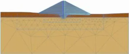
Fig.1.Finite element mesh of analyzed cross-section.

where c is the cohesion;φ is the friction angle;prefis the reference stress;σ3is the minor principal stress,which is the effective conf i ning pressure applied in a triaxial test;andis the reference stiffness modulus corresponding to the reference stresspref,whichdependsontheminorprincipal stressσ3andis determined from a triaxial stress-strain curve for a mobilization of 50%of the maximum shear strength qf.qfis evaluated with the Mohr-Coulomb failure criterion.The unloading/reloading path is modeled as purely(linear)elastic with the reference Young'smodulusforunloading/reloading.Thederivationof the parameters is depicted in Schanz et al.(1999).
In the hardening soil model,two different hardening mechanisms(i.e.,isotropic and deviatoric)account for the history of stress paths.Therefore,a shear hardening yield surface(cone)as indicated in Fig.2 isintroduced.Forcompressive (isotropic)stress paths,a cap-type yield surface is used to close the elastic region.Due to shear hardening,the shear yield locus can expand to the Mohr-Coulomb failure surface while the cap expands due to volumetric hardening as a function of the preconsolidation stress.A detailed description of the hardening soil model can be found in Schanz et al.(1999).
2.3.Applied finite element model and parameters
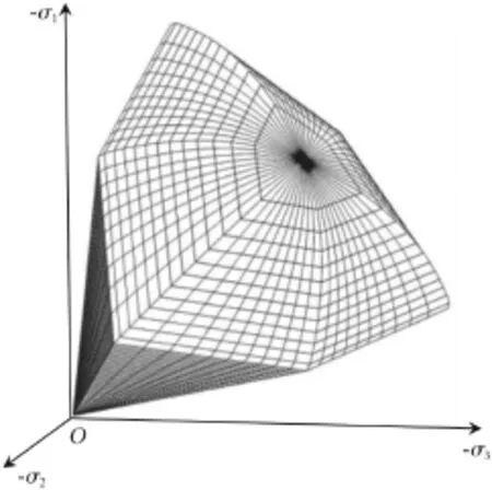
Fig.2.Yield contour of hardening soil model in total stress space (Plaxis,2015;Schanz et al.,1999).
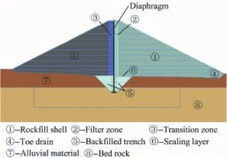
Fig.3.Material zoning for numerical simulation.
Fig.3 depicts the zoning of the dam body,which was taken into account with six different zones(zones 1 through 6)using the hardening soil model.The bedrock(zone 8)was assumed to be nearly rigid and therefore modeled as linear elastic.For the alluvial subsoil(zone 7),the hardening soil model was chosen.The concrete core with a thickness of 0.4 m was modeled in a linear elastic manner as a plate.For the soilstructure interaction(skin friction),interface elements were placed on both sides of the core.The interaction between soil and structure is controlled by the interface with the reduction factor for skin friction Rinter(Potyondy,1967).The parameter relates the interface strength to the soil strength.Since no triaxial tests have been available,material parameters from literature(Lofquist,1951;Leps,1970;Marachi et al.,1972; Marsal,1967;Saboya and Byrne,1993;Douglas,2002; Xiao et al.,2016)and from back-calculations of similar dams were used to obtain a range of characteristic parameters for different zones.Based on the experience of previous studies(Tschernutter and Nackler,1991;Kainrath,2009, 2010;Tschernutter et al.,2011),upper and lower bounds of characteristic parameters were chosen for the main inf l uencing zones to identify their inf l uence on the rheological behavior of the dam.For this study,the focus was steered to the resulting structural forces in the concrete core.Therefore,the inf l uences of the material parameters of the rockfill shells(zone 1)and the backfilled trench for the core footing(zone 5)as well as the roughness of the concrete core on the rheological behavior of the dam were studied through variation of their values. Furthermore,the bedding condition of the core footing was examined.The general variations of the parameters used in this study are summarized in Table 1.The parameters with upper and lower bounds according to Table 1 are given in Table 2.A more detailed description of the parameters for the hardening soil model is given in Schanz et al.(1999).The values of stiffness E of the bedrock(zone 8)and the reinforced concrete core used forthe linearelastic modelwere 3×10⁶kN/m and 3×10⁷kN/m,respectively.The values of Poisson's ratio ν of the bedrock(zone 8)and the reinforced concrete core were 0.20 and 0.15,respectively.
The numerical analysis of the construction process was carried out in 19 phases in total,which can be summarized in four main phases:calculation of the initial stress state under gravity loading and reset of the initial deformation to zero,soil excavation of the upper parts of the alluvial layer and the trench for the concrete core footing,simultaneous construction of the concrete core,and upstream and downstream dam zones with a layer thickness of about 2 m,impounding to the maximum water level.

Table 1Overview of models and parameter variations used in current study.

Table 2Parameters for hardening soil model used in this study and their bounds.
3.Results and discussion
3.1.Stress and deformation analysis
Fig.4 depicts the distribution of effective horizontal stress of the dam at the end of construction(EOC)and at the maximum water level(MWL).As can be seen in the f i gures, the effective horizontal stress in the downstream dam body signif i cantly increases in the zones adjacent to the concrete core due to the impounding,which is representative for dams with a central core and is caused by a rotation of the principal stress in the lowest third of the downstream dam body. High horizontal stresses and the low height above the base inhibit the mobilization of signif i cant resistance in this area. This leads to horizontal deformations and a structural loading of the concrete core.For this reason,it is of interest how the material of the shell(zone 1)and the backfilled trench(zone 5)inf l uences the horizontal deformation.The horizontal deformation of the concrete core is depicted in Fig.5,with positive values representing the deformation towards downstream and negative values representing the deformation towards upstream.The results show that the absolute horizontal deformation of the concrete core due to impounding is mainly governed by the stiffness of the rockfill shells.A stiff shell zone as specified in model D-2-2 leads to a signif i cantly less horizontal deformation of the core.Fig.5 shows that the absolute horizontal deformation of the core is not affected by the skin friction.The different angles of internal friction for the f i lter and transition zone cause the differences in the horizontal deformation at the end of construction.
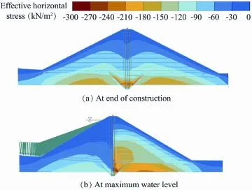
Fig.4.Distribution of effective horizontal stress at end of construction and at maximum water level.
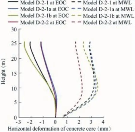
Fig.5.Horizontal deformation of concrete core at end of construction (EOC)and at maximum water level(MWL).
Fig.6 depicts the differential rotation of the concrete core due to impounding,with negative values representing the differential rotation in the clockwise direction.It can be observed that the model D-2-1a with low stiffness of the material in zone 5(backfilled trench)obtains signif i cantly higher differential rotations in the lower third of the core.This causes a higher curvature accompanied by higher bending moments in the concrete core.Fig.6 shows that a lower skin friction(model D-2-1b)results in higher curvatures of the core.A lower skin friction(model D-2-1b)does not affect the horizontal deformation of the core.Furthermore,differences in the angle of internal friction on both sides of the core lead to deformations during the construction process.It can be concluded that the material and the design of the zones adjacent to the core have a signif i cant inf l uence on the horizontal deformation behavior of the core.As a consequence,a low material stiffness for the downstream shell as well as for the trench backfilling leads to more horizontal deformation during impounding.
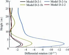
Fig.6.Differential rotation of concrete core during period from end of construction to moment with maximum water level.

Fig.7.Distribution of effective vertical stress at end of construction and at maximum water level.
It is common knowledge that the stress distribution within structures depends on the stiffness of different zones,and higher stress always occurs in zones with a higher stiffness. With regard to dams with a concrete core,the stiffness of the core is around 1000 times larger than the stiffness of the adjacent zones.As a consequence,arching effects occur on both sides of the core.The vertical stress distribution at the end of construction and at the maximum water level is depicted in Fig.7.This indicates arching effects on both dam shoulders.The decrease of the vertical stress on both sides of the core is an indication of the redistribution of stress between the soft shells and the stiff concrete core.Consequently,the concrete core is receiving additional vertical loads from the dam body during the construction process.For this reason,the way in which the roughness of the concrete core in fl uences the stress distribution adjacent to the core is of interest.For model D-2-1,a typical rough concrete surface was assumed.For model D-2-1b,a smooth surface(with a slip layer,sliding zone)was assumed.Fig.8 shows the infl uence of the concrete surface roughness on the effective vertical stress.
The model with the smoother core surface(D-2-1b)leads to higher vertical stresses in the dam body at the end of construction,accompanied by signif i cantly lower compressive stress in the core(Fig.8(a)).It can be seen from the vertical stress distribution in Fig.8(a)that the vertical stress in the zones next to the core obtained from the model with the smooth concrete surface(D-2-1b)is much higher than that obtained from the model with the rough concrete surface (D-2-1).The vertical stress obtained from the model with the smooth surface(D-2-1b)at the maximum water level is much lower than that at the end of construction.This is in accordance with the results for the compressive stress in the core shown in Fig.9.Arching effects in the dam control the stress distribution between the(soft)dam and the(stiff)core. The compressive stress in the concrete core obtained from the model with a smooth concrete surface(D-2-1b)is signif icantly lower than that obtained from the model with the rough surface(D-2-1).On the basis of these results,it can be concluded that a smooth core surface reduces the susceptibility to arching effects in the dam.The arching effects disappear due to impounding,leading to a lower compressive stress in the core.
3.2.Structural forces in concrete core
The structural forces in the core depend on the deformation behavior of the dam.The relation between the mass of the concrete core and the mass of the dam body provides information about the inf l uence of the core stiffness on the load distribution in the dam.Since the mass of the concrete core is less than 1%of the mass of the shells,the core does not create any additional horizontal resistance.The structural forces in the core depend on the deformation state of the core,which is governed by the dam behavior.The maximum structural forces occur in the lowest part of the core at the maximum water level.Their magnitude dependson the bedding conditions of the core footing in the bedrock.
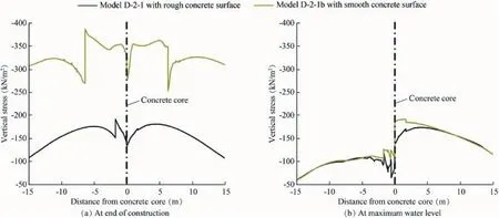
Fig.8.Distribution of effective vertical stress adjacent to core for two different concrete surface roughnesses at the end of construction and for the first impounding to maximum water level.
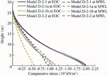
Fig.9.Compressive stress distribution in concrete core at the end of construction and at the maximum water level.
Fig.10 depicts the bending moment distribution of the concrete core for two cases.For the first case(model D-2-1),a rigid connection between the core footing and the bedrock was assumed.For the second case(model D-2-1c),a contact area meeting a Mohr-Coulomb failure criteria was introduced.The model with the rigid connection leads to unrealistic high bending moments in the core,while the second model provides more realistic results,since local failure due to a slightly opening gap occurs in the joint between the bedrock and the concrete core,resulting in a lower bending moment.Lesser restraining of the core footing reduces the bending moment signif i cantly.
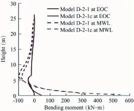
Fig.10.Inf l uence of core base bedding conditions on bending moment in concrete core.

Fig.11.Interaction between bending moment and axial compressive force for a reinforced cross-section.
The bearing capacity of the core depends on the interaction between the compressive stress and the bending moment.Fig.11 depicts the M-N interaction diagram for an exemplary cross-section with 15 cm2reinforced area on each side.The whole range of interaction from pure bending to axial load can be visualized with this diagram.For each section of the core in each state of loading,the interaction between the compressive stress and the bending moment must be within the red M-N interaction curve.A stress state exceeding the red M-N interaction curve leads to a yielding of the reinforcement and a failure of the concrete core.The values of the compressive stress and the bending moment for each step of model D-2-1c,including the start of construction,end of construction,maximum water level,and minimum water level,are depicted in the f i gure as a numbered blue line.It can be seen that,during construction,only compressive stress occurs in the concrete core,while,during the impounding,the bending moment increases,along with a reduction of the compressive stress,slightly reducing the bearing capacity.
4.Conclusions
This paper contributes to the numerical analysis of the behavior of dams with a reinforced concrete core as a sealing element.Based on the results of this study,the following conclusions can be drawn for the load and deformation behavior of the dam:
(1)The absolute horizontal deformation of the reinforced concrete core due to impounding is mainly governed by the stiffness of the rockfill shells.A stiffer material leads to lower horizontal displacements.
(2)A bad compaction or soft material for backfilling of the downstream core footing trench creates higher horizontal deformations in the lowest part of the core,accompanied by high structural forces.
(3)Arching effects in the dam body arise due to rough surface conditions on the core.Those effects induce high compressive stresses in the core during construction,which dissipate during impounding.
(4)The structural forces in the reinforced concrete core depend on the restraining of the footing.A more f l exible footing leads to lower bending moments and allows higher dam heights.
(5)The bearing capacity of the reinforced core depends on the interaction between thebending momentand the compressive stress.Both values change due to construction and impounding of the dam.Both values must be checked for each cross-section of the concrete core.
(6)Up to a limited dam height of about 30—40 m,the core can be designed and constructed without sliding foil between the embankment and the concrete core.For higher dams the application of sliding foil on both sides of the core is necessary to obviate arching effects and reduce the compressive stress in the core.
Douglas,K.J.,2002.The Shear Strength of Rock Masses.Ph.D.Dissertation. University of New South Wales,Sydney.
Duncan,J.M.,Chang,C.Y.,1970.Non-linear analysis of stress and strain in soil.J.Soil Mech.Found.Div.96(5),1629—1653.http://dx.doi.org/ 10.1061/JSFEAQ.0001388.
Duncan,J.M.,Byrne,P.,Wong,K.S.,Mabry,P.,1980.Strength,Stress-stain and Bulk Modulus Parameters for Finite Element Analyses of Stresses and Movements in Soil Masses.University of California,Berkeley.
Hupfauf,B.,1991.Das Tragverhalten von Staud¨ammen in Abh¨angigkeit von der Dichtungsart.Ph.D.Dissertation.University of Innsbruck,Innsbruck (in German).
Kainrath,A.,2009.Ein Beitrag zur Untersuchung von Verformungsproblemen an Steinschu¨ttd¨ammen Mittels Elasto-plastischer Stoffgesetze.Vienna University of Technology,Vienna(in German).
Kainrath,A.,2010.Numerical Back-calculation of Bockhartsee Dam Heightening.Vienna University of Technology,Vienna(in German).
Lackinger,B.,1980.Das Tragverhalten von Staud¨ammen Mit Membranartigen Dichtungen.University of Innsbruck,Innsbruck(in German).
Leps,T.M.,1970.Reviewoftheshearingstrengthofrockfill.J.SoilMech.Found. Div.96(4),1159—1170.http://dx.doi.org/10.1061/JSFEAQ.0001365.
Lofquist,B.,1951.Calculating a concrete-core wall.In:Proceedings of the IV International Congress on Large Dams.New Delhi,p.68.
Marachi,N.D.,Chan,C.K.,Seed,B.H.,1972.Evaluation of properties of rockfi ll materials.J.Soil Mech.Found.Div.98(1),95—114.http://dx.doi.org/ 10.1061/JSFEAQ.0001658.
Marsal,R.J.,1967.Large scale testing of rock- fi ll materials.J.Soil Mech. Found.Div.93(2),27—43.
Plaxis,2015.Material Models Manual.Plaxis B.V.,Delft.
Potyondy,J.G.,1967.Skin friction between various soils and construction materials.Geotechniquˊe 11(4),339—353.http://dx.doi.org/10.1680/ geot.1961.11.4.339.
Rammer,L.,1986.Wirklichkeitsnahe Ermittlung der Spannungs-und Verformungszust¨ande von Staud¨ammen Mit Membranartigen Dichtungen Unter Beru¨cksichtigung der R¨aumlichen Tragwirkungen.University of Innsbruck,Innsbruck(in German).
Saboya Jr.,F.,Byrne,P.M.,1993.Parameters for stress and deformation analysis of rockfill dams.Can.Geotech.J.30(4),690—701.http:// dx.doi.org/10.1139/t93-058.
Schanz,T.,Vermeer,P.A.,Bonnier,P.G.,1999.The hardening soil model: Formulation and verif i cation.In:Beyond 2000 in Computational Geotechnics-10 Years of Plaxis.Balkema,Rotterdam,pp.1—16.
Schober,W.,1982.Concrete core diaphragm walls for high embankment dams.In:Proceedings of the 14th ICOLD Congress,Rio de Janeiro.
Schober,W.,1984.Membranartige Betonkerndichtungen Fu¨r Hohe Staud¨amme.University of Innsbruck,Innsbruck(in German).
Schober,W.,Henzinger,J.,1984.Membranartige Betonkerndichtungen fu¨r hohe Staud¨amme.University of Innsbruck,Innsbruck(in German).
Schober,W.,Hupfauf,B.,Lercher,H.,Rammer,L.,1987.Der Staudamm Bockhartsee-Bauerfahrung und Auswertung der Kontrollmessungen.University of Innsbruck,Innsbruck(in German).
Schober,W.,2003.Embankmentdams:Researchanddevelopment,construction and operation.In:Austrian National Committee on Large Dams,Vienna.
Tschernutter,P.,Nackler,K.,1991.Construction of Feistritzbach dam with central asphaltic concrete membrane and the inf l uence of poor quality rock on fill behaviour.In:Proceedings of the XVII ICOLD Congress.Vienna, pp.435—442.
Tschernutter,P.,2001.Inf l uence of soft rock-fill material as dam embankment with central bituminous concrete membrane.Front.Archit.Civ.Eng. China 5(1),435—442.http://dx.doi.org/10.1007/s11709-010-0016-3.
Tschernutter,P.,Seiwald,S.,Kainrath,A.,2011.Rheological behavior of an embankment dam after heightening.In:Proceedings of the 6th International Conference on Dam Engineering.LNEC,Lisboa,pp.1193—1219.
Xiao,Y.,Liu,H.,Zhang,W.G.,Liu,H.L.,Yin,F.,Wang,Y.Y.,2016.Testing and modeling of rockfill materials:A review.J.Rock Mech.Geotech.Eng. 8(3),415—422.http://dx.doi.org/10.1016/j.jrmge.2015.09.009.
Yagin,V.P.,Davydov,I.A.,Mik,V.V.,Leimann,T.V.,1998.Earth dams with concrete and reinforced-concrete core walls.Hydrotech.Constr.32(2), 70—75.http://dx.doi.org/10.1007/BF02905861.
Received 26 October 2015;accepted 12 February 2016
*Corresponding author.
E-mail address:peter.tschernutter@kw.tuwien.ac.at(Peter Tschernutter).
Peer review under responsibility of Hohai University.
http://dx.doi.org/10.1016/j.wse.2016.11.006
1674-2370/©2016 Hohai University.Production and hosting by Elsevier B.V.This is an open access article under the CC BY-NC-ND license(http:// creativecommons.org/licenses/by-nc-nd/4.0/).
©2016 Hohai University.Production and hosting by Elsevier B.V.This is an open access article under the CC BY-NC-ND license(http:// creativecommons.org/licenses/by-nc-nd/4.0/).
 Water Science and Engineering2016年3期
- Water Science and Engineering的其它文章
- Self-adaptive Green-Ampt inf i ltration parameters obtained from measured moisture processes
- Distributed hydrological models for addressing effects of spatial variability of roughness on overland flow
- Analysis of working behavior of Jinping-I Arch Dam during initial impoundment
- Calibration and performance of two different constitutive models for rockfill materials
- Numerical stress-deformation analysis of cut-off wall in clay-core rockfill dam on thick overburden
- Numerical simulation of seismic damage and cracking of concrete slabs of high concrete face rockfill dams
