Stability analysis of unsaturated soil slope during rainfall inf i ltration using coupled liquid-gas-solid three-phase model
*
State Key Laboratory of Hydraulic Engineering Simulation and Safety,Tianjin University,Tianjin 300072,China
Stability analysis of unsaturated soil slope during rainfall inf i ltration using coupled liquid-gas-solid three-phase model
Dong-mei Sun*,Xiao-min Li,Ping Feng,Yong-ge Zang
State Key Laboratory of Hydraulic Engineering Simulation and Safety,Tianjin University,Tianjin 300072,China
Available online 17 October 2016
Generally,most soil slope failures are induced by rainfall inf i ltration,a process that involves interactions between the liquid phase,gas phase, and solid skeleton in an unsaturated soil slope.In this study,a loosely coupled liquid-gas-solid three-phase model,linking two numerical codes, TOUGH2/EOS3,which is used for water-air two-phase flow analysis,and FLAC3D,which is used for mechanical analysis,was established.The model was validated through a documented water drainage experiment over a sandy column and a comparison of the results with measured data and simulated results from other researchers.The proposed model was used to investigate the features of water-air two-phase flow and stress fields in an unsaturated soil slope during rainfall in fi ltration.The slope stability analysis was then performed based on the simulated water-air two-phase seepage and stress fields on a given slip surface.The results show that the safety factor for the given slip surface decreases fi rst,then increases,and later decreases until the rainfall stops.Subsequently,a sudden rise occurs.After that,the safety factor decreases continually and reaches its lowest value,and then increases slowly to a steady value.The lowest value does not occur when the rainfall stops,indicating a delayed effect of the safety factor.The variations of the safety factor for the given slip surface are therefore caused by a combination of pore-air pressure,matric suction,normal stress,and net normal stress.
Coupled liquid-gas-solid three-phase model;Pore-air pressure;Unsaturated soil slope stability;Rainfall in fi ltration
1.Introduction
A landslide is usually induced by rainfall inf i ltration,which is one of the most important subjects in the field of geotechnical engineering.As rainwater inf i ltrates the soil slope,due to the advancing wetting front,the pore-air pressure in the unsaturated zone increases and the matric suction decreases, compromising slope stability(Sun et al.,2015).Meanwhile, the inf i ltration of rainwater causes a change in the effective stress,leading to variations of porosity;in turn,the variations of the porosity affect the seepage properties(Xu et al.,2009). Therefore,the interactions between the liquid phase,gas phase,and solid skeleton in an unsaturated soil slope should be considered in the analysis of unsaturated soil slope stability during rainfall inf i ltration.
In general,analysis of soil slope stability during a rainfall event is performed using the limit equilibrium methods and by considering only the changes in liquid-phase flow(Cho and Lee,2001;Collins and Znidarcic,2004).The changes in gas-phase flow are usually ignored due to the diff i culties in obtaining the magnitude of pore-air pressure(Sako et al., 2011).The gas-phase flow induced by rainfall has a signif icanteffecton the seepageprocessin thesaturatedunsaturated soil and on the soil slope stability(Wang et al., 1998;Sun et al.,2007,2009;Guo et al.,2008;Regmi et al.,2010;Kuang et al.,2013;Sun et al.,2015).Anuncoupled model for slope stability analysis considering the gas phase flow has been developed based on the limit equilibrium method and according to the water-air two-phase seepage field calculated from a multi-phase flow model (Sun et al.,2009;Regmi et al.,2010).Although this uncoupled model is relatively easy to implement using existing available multiphase flow models,the dependence of hydraulic properties(such as the porosity and hydraulic conductivity)on deformation is not taken into account.A coupled model of slope stability analysis considering the gasphase flow was established by solving a liquid-gas-solid three-phase mathematical model to obtain the water-air twophase seepage and stress conditions(Hu et al.,2011).The coupled model can produce the most realistic results,but it is very diff i cult to establish a fully coupled three-phase model. Thus,a loosely coupled three-phase model is a good choice due to the ease of implementation and its satisfying accuracy. A loosely coupled methodology,called TOUGH2-FLAC3D, proposed by Rutqvist et al.(2002),can be adopted to investigate the coupled multiphase fluid flow and soil skeleton deformation.TOUGH2(Pruess et al.,1999)was used for multiphase fluid flow simulation,while FLAC3D(ICGI,2002) was used for mechanical simulation.
In this study,the loosely coupled method based on TOUGH2-FLAC3Dwas used to investigate the features of water-air two-phase flow and stress fields in an unsaturated soil slope induced by rainfall inf i ltration.Then,a method for calculation of the safety factor for a given slip surface was developed using the simulated water-air two-phase seepage and stress fields.
2.Coupled liquid-gas-solid three-phase model
TOUGH2,a computer code for non-isothermal multiphase multi-component flow in three-dimensional porous and fractured media,is used for multiphase fluid flow simulation, in which the deformation of the soil is not taken into account. The TOUGH2 simulator was chosen in this study because its source code is available for further modif i cation.The TOUGH2/EOS3 model was adopted for the study.EOS3 is a module of the TOUGH2 simulator for the two-phase flow for water and air,in which two fluid phases,the liquid phase (subscript l)and gas phase(subscript g),are considered.The liquid phase consists of water(superscript w)and dissolved air(superscript a).The gas phase consists of air(superscript a)and water vapor(superscript w).Thus,there are two components,water and air.FLAC3D,a three-dimensional explicit finite-difference computer program for solving geomechanical problems,is used to simulate the mechanical system,in which the airflow induced by rainfall is not included.In FLAC3D,an embedded programming language, the FISH language,enables the users to def i ne new variables and functions.FLAC3Dcan communicate with TOUGH2 via this feature.
When rainwater inf i ltrates the soil slope,the liquid saturation,the distributions of pore-water pressure and pore-air pressure,and matric suction change,leading to changes in the soil density,the effective stresses,and the strains of soils.The changes in the strains affect the porosity of soils, causing changes in the intrinsic permeability and the capillary pressure,and further inf l uencing the seepage processes.Therefore,in the coupled liquid-gas-solid three-phase model,the porosity,intrinsic permeability,and capillary pressure in TOUGH2 should be updated every time step.Then, the pore pressures should be updated in FLAC3Dto calculate the new porosity in the next time step.
2.1.Modif i cations to mechanics
In the multiphase fluid flow process,information about liquid saturation and pore pressures(pore-water and pore-air pressures)can be provided by TOUGH2,which is used to calculate the average pore pressure through Eq.(1)(Rutqvist et al.,2002):

where p is the average pore pressure,Slis the liquid saturation, and pland pgare the pore-water pressure and pore-air pressure,respectively(the pore pressures refer to the atmosphere pressure).
By substituting the pore pressure into Eq.(1),FLAC3Dcan be used to calculate the effective stress,the strain,the displacement,and the stress.The change in porosity due to the deformation of the soil can be expressed as(Coussy,1995; Bary,2002)

where φ is the porosity,dφ is the change in porosity,φ0is the porosity at zero stress(the initial state),3vis the volumetric strain increment,and3sis the shear strain increment.
2.2.Modif i cations to fluid flow
Deformation due to the mechanical response is translated to the increase or decrease in porosity.The intrinsic permeability is corrected according to the Kozeny-Carman equation (Chapuis and Aubertin,2003):

where K is the corrected intrinsic permeability,and K0is the intrinsic permeability at zero stress.
The capillary pressure is modified with the current intrinsic permeability and porosity,according to the function proposed by Leverett(1941):

where pcLis Leverett's corrected capillary pressure,and pcis the calculated capillary pressure depending on the liquid saturation.
2.3.Loosely coupled algorithm
The proceduresofthe method ofloosely coupling TOUGH2 and FLAC3Dare shown in Fig.1,where pgn,pln,Sln, pcln,φn,and Knare the pore-air pressure,pore-water pressure, liquid saturation,corrected capillary pressure,updated porosity,and intrinsic permeability at the nth time step, respectively.Before the coupling,some work needed to be done.First,the model f i les in TOUGH2 and FLAC3Dwere established.Then,the initial steady state was obtained by running TOUGH2 when the porosity was φ0(at zero stress). Meanwhile,FLAC3Dwas executed to reach the static equilibrium under the gravitational load and the corresponding porosity φ0was obtained.The porosity φ0was then mapped to TOUGH2 elements and the permeability K0was updated. Afterwards,the process of coupling FLAC3Dand TOUGH began.TOUGH2 was executed for the first time step from t0to t1(t0and t1are the initial time and end time of the first time step,respectively).During the first time step,the porosity φ0and permeability K0were assigned in the input f i le.When convergence was reached,the liquid saturation,pore-air pressure,and pore-water pressure at TOUGH2 elements were obtained and sent to the FLAC3Dnodes through weighted distance interpolation.Then,the average pore pressure was calculated using Eq.(1).FLAC3Dwas run under the average pore pressure at FLAC3Dnodes until an equilibrium state was reached.After that,the strain increment occurred,and the change in porosity at FLAC3Delements could be calculated using Eq.(2).The updated porosity at FLAC3Delements was sent back to the TOUGH2 elements through interpolation.The updated intrinsic permeability and capillary pressure in TOUGH2 were calculated according to Eqs.(3)and(4).Using the updated flow parameters,TOUGH2 was again executed for the next time step.Then,the processes above were repeated until the specified simulation time T was reached.
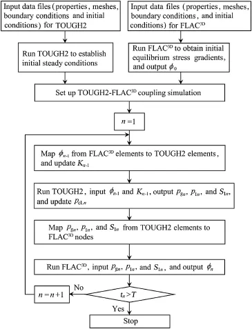
Fig.1.Flow chart for loosely coupled algorithm.
The length of every time step was controlled by TOUGH2/ EOS3.At the end of every time step,the liquid saturation and pore pressures(pore-water pressure and pore-air pressure) could be used to calculate the new average pore pressures at FLAC3Dnodes.FLAC3Dwas run to obtain an equilibrium state under the average pore pressure for the same time step, and the new porosity obtained by FLAC3Dwas then sent back to TOUGH2 for the next time step.Therefore,data were transferred between FLAC3Dand TOUGH2 in the same time period.
3.Validation of three-phase model
Many researchers have proven the applicability of the coupled liquid-gas-solid three-phase model(Lewis and Schref l er,1987;Schref l er and Zhan,1993;Schref l er and Scotta,2001;Gawin et al.,1995,1996;Ehlers et al.,2004; Nagel and Meschke,2010;Hu et al.,2011)using water drainage experiments over a soil column,as first conducted by Liakopoulos(1965).The column in this experiment had a height of 1.0 m,was packed with Del Monte sand,and was instrumented to measure the moisture tension at different points along the column.Before the experiment,water was added continuously from the top and was allowed to flow freely at the bottom of the column through a f i lter until uniform flow conditions were established.Then,the water inflow at the top of the column was ceased and the tension meter readings were recorded for 120 min.The initial porosity and hydraulic properties of Del Monte sand were measured by Liakopoulos(1965)in an independent experiment.Even though the mechanical parameters of Del Monte sand were not measured,they have been obtained by previous studies and were used by other researchers(Lewis and Schref l er,1987; Schref l er and Zhan,1993;Schref l er and Scotta,2001;Gawin et al.,1995,1996;Ehlers et al.,2004;Nagel and Meschke, 2010;Hu et al.,2011).The constitutive model was assumed to be the elastic model and the relevant parameters of Del Monte sand are shown in Table 1.
In the numerical model,the capillary pressure and relative liquid permeability krl,which is dependent on liquid saturation, are described in Eqs.(5)and(6),respectively(Liakopoulos, 1965):

The relative gas permeability,krg,was assumed according to Brooks and Corey(1966),as shown in Eq.(7):

Table 1Material parameters of Del Monte sand in numerical simulation.

The constant 1.0×10⁻⁴in Eq.(7)represents the lower limit of the relative gas permeability.The atmospheric boundary conditions,Pg=patmand Xga=0.999,where Pgis the gas-phase pressure,and Xgais the mass fraction of air in the gas phase,were applied at the top of the column.The boundary conditions,Pl=1.013×10⁵Pa and Xla=1.0×10⁻¹⁰,were applied at the bottom,where Plis the gas-phase pressure,and Xlais the mass fraction of air in the liquid phase.No deformation was allowed,i.e.,uh=0 and uv=0,where uhwas the horizontal displacement,and uvwas the vertical displacement. For the lateral boundary uh=0 and no water flow was applied. However,due to the micro-gaps between the soil and the cylinder,a little air in the soil could escape in the experiment.The atmospheric boundary conditions,Pg=patmand Xga=0.999, were therefore applied at the lateral boundary(Schref l er and Zhan,1993;Hu et al.,2011).The initial conditions were set to be saturated for the liquid phase,i.e.,Pl=1.013×10⁵Pa and Xla=1.0×10⁻¹⁰,for the whole domain.
The time evolution of the experimental and simulated porewater pressure heads at different locations are shown in Fig.2(a),wherehisthedistancefromthebottomofthecolumn. The simulated results deviated greatly from the experimental results at the beginning of the drainage process,and then they were basically similar.The simulated and experimental porewater pressure head prof i les at different times are shown in Fig.2(b).The simulated pore-water pressure head prof i les at t=60minandt=120minagreedwiththeexperimentalresults, whiletherewasasmalldeviationatt=30min.Duringthewater drainage process,since air inflowing through the top of the column could not completely replenish the remaining space after water flowed out,air was suckedinto theporevolume,and a pressure lower than the atmospheric pressure,i.e.,a negative pore-air pressure,formed in the sand column(Fig.2(c)).Then, with the continuous drainage of water and inf i ltration of air,the zone of lower pore-air pressure moved gradually towards the middle height of the sample,and,correspondingly,the lowest pore-air pressure increased gradually towards zero.The simulated outflow rate of water from the bottom of the column was compared with the experimental and other researchers'results (Fig.2(d)).The water outflow rates obtained from all of thenumericalmodelswerefarlowerthantheexperimentalresultsat the beginning of the drainage process.The reason might be that thedeformationofthesoilcolumnintheexperimentinducedby thewaterinflowandpercolationwasnotfullycompletedbefore theexperimentwascarriedout.Therefore,thedrainageofwater was not only affected by gravity,but also affected by the deformation of the soil column.While the deformation of the soil column was assumed to have been fully completed in the numerical model,the simulated outflow rate of water was therefore lower than the experimental results at the beginning, and deviation between the simulated and experimental porewater pressures occurred.The prof i les of vertical displacement at different times are shown in Fig.2(e).The effective stress of the soil increased with the water drainage,and settlement of the sandy column occurred.The f i nal settlement of 3.9 mm at the top of the soil was basically identical with those obtained by other researchers(Schref l er and Zhan,1993; Schref l er and Scotta,2001;Gawin et al.,1996).
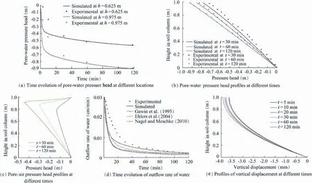
Fig.2.Simulated and experimental results.
Fig.3 exhibitsthe prof i les ofporosity increments at different times.The negative porosity increment increases with height in the soil column due to the gravitational loading.During the process of water drainage,the porosity further decreases,as the pore where the water drained out in the column is compressed by the weight of soil column.
4.Slope stability analysis
4.1.Shear strength equation of unsaturated soils
With consideration of the contributions of matric suction and pore-air pressure to the shear strength,the modified Mohr-Coulomb failure criterion with two independent stress variables is written as follows(Fredlund et al.,1978):

where τfis the shear strength of unsaturated soil,cˊis the effective cohesion,φˊis the angle of internal friction associated withthenetnormalstressstatevariableσ*n(σ*n=σn-pg,where σnis the normal stress),and φbisthe angle indicatingthe rate of increase in shear strength relative to the matric suction.

Fig.3.Prof i les of porosity increment at different times.
New strength models have been developed considering the nonlinearity of φbrelated to the matric suction in a practical manner(Fredlund et al.,1996;Vanapalli et al.,1996;¨Oberg and S¨allfors,1997).Based on these models,Vanapalli et al.(1996) proposed that the term tanφbin Eq.(8)could be transformed into S*tanφˊ,where S*is the effective liquid-phase saturation, andS*=(Sl-Slr)/(Sls-Slr),,withSlrbeingtheresidualliquid saturation and Slsbeing the saturated liquid saturation.
In this way,the shear strength related to the matric suction can be expressed as

It can be seen that Eq.(9)provides a smooth transition into the shear strength equation for saturated soils.When the soil becomes saturated,the pore-water pressure equals the pore-air pressure and Eq.(9)takes the form of a shear strength equation for saturated soils,as shown below:

4.2.Evaluation of safety factor using stress field
In this study,a new method(Cho and Lee,2001)was used to perform the slope stability analysis with consideration of the effects of airflow and soil deformation.This method fully utilizes the simulated results obtained from the coupled liquidgas-solid three-phase model,water-air two-phase flow,and stress fields,while in the traditional limit equilibrium method only the seepage field is used.The safety factor for the given slip surface is def i ned as

where τiis the mobilized shear stress at the ith point on the slip surface,and Γ is the total length of unit slip surfaces.
In Eq.(9),the net normal stress on the slip surface can be def i ned as

where α is the angle of the slip surface to the horizontal plane;is the net normal stress in the horizontal direction,and=σx-pg,where σxis the normal stress in the horizontal direction;is the net normal stress in the vertical direction, and=σz-pg,where σzis the normal stress in the vertical direction;and τxzis the shear stress along the x-z plane.
The mobilized shear stress τiin Eq.(11)can be expressed as

When the soil becomes saturated,the pore-air pressure is equal to the pore-water pressure,so the matric suction becomes zero and the net stress becomes effective stress.
5.Model studies
5.1.Geometry and soil parameters
In this study,an idealized homogeneous isotropic soil slope with two inclination angles,an angle of 45。in the lower part and an angle of 26.7。in the upper part in regard to the horizontal plane,and with a height of 21 m and a total length of 46 m in the bottom along the x direction,was used(Fig.4). The groundwater table,with a height of 10 m at the lower ground surface,was assumed to be horizontal.All the processes involved in the numerical simulation were assumed to occur isothermally at 15。C.In this study,we mainly focused on the inf l uences of the rainfall inf i ltration process on the variations of soil slope safety factor,so a f i xed given slip surface obtained from the slope stability program embodied in FLAC3D,rather than a critical slip surface,was used.Actually, the critical slip surface continually changed with the rainfall event.The f i xed given slip surface was circular with a radius of 22.24 m(Fig.4).Section A-A was in the middle of the circular arch.Both the observation points B and C were located on the circular arch,and their heights were 20.75 m and 13.6 m,respectively.
As no experimental testing was done,the soil properties related to the unsaturated soil were taken from van Genuchten (1980),and the mechanical parameters were taken from Cheng et al.(2007).The constitutive model of the soil was assumed to be Mohr-Coulomb model.The capillary pressure-liquid saturation relationship was described by the van Genuchten (1980)model because of its applicability to various kinds of soils,expressed as

where p0is the air entry pressure,λ is a model parameter related to the degree of soil uniformity,and pmaxis the maximum absolute value of the negative capillary pressure, and is usually equal to 107Pa.
The relative liquid permeability dependent on the liquid saturation was described by the van Genuchten-Mualem model(Mualem,1976;van Genuchten,1980)and can be expressed as

Fig.4.Slope prof i le and given slip surface used in numerical study.

The relative gas permeability krgis chosen as one of the following two forms,the second of which is from Corey (1954):

5.2.Simulation of rainfall inf i ltration into soil slope
A rectangular mesh was used in this study.The f i ne vertical mesh,with a size ranging from 0.1 m(near the surface of the domain)to 0.6 m(in the saturated zone),was used.The size of the horizontal mesh ranged from 0.5 m to 1.8 m.The initial conditions in the numerical simulation were set as the capillary-gravity equilibrium state in TOUGH2 and the mechanical equilibrium state in FLAC3D.The boundary conditions were specified as follows:(1)the atmospheric boundary condition, pg=patmand Xga=0.999,was applied at the ground surface of the slope in the TOUGH2 model;and(2)both lateral boundaries and the base of the model were represented by a no-flow boundary in the TOUGH2 model,zero horizontal displacement was used for the left and right lateral boundaries,and the domain base was fully constrained in the FLAC3Dmodel.The sink term for rainfall,m(t)=ρwAeQr(t),was applied at the surface of the soil domain,where ρwis the density of water,Aeis the effective area for rainwater inf i ltration,and Qris the rainfall intensity.When the rainfall stopped,the sink term was removed.The rainfall intensity was set at 5.0 mm/h(i.e., 1.38×10⁻⁶m/s),which was greater than the hydraulic conductivity,1.0×10-6m/s,and the rainfall period was one day. It is noted that the inf l uence of rainfall runoff on the slope stability was not considered in this study.Through the transient analysis for a simulation time of t=10 d(one day for rainfall duration,and nine days after rain stopped),the temporal process of seepages and stresses could be obtained.
5.2.1.Analysis of seepage variations
Fig.5 shows the liquid saturation,pore-water and pore-air pressure heads,and capillary pressure head prof i les at section A-A prior to rainfall(t=0),as well as 1.0 d(t=1.0 d)and 10.0 d(t=10.0 d)after the rainfall begins.At t=1.0 d and t=10.0 d,the depths of the wetting front are about 1.0 and 2.2 m,respectively,indicating that the wetting front continues to advance downward even after the rainfall stops.Before rainfall,the pore-water pressure head is linearly distributed throughout the domain,while the pore-air pressure head in the unsaturated zone is about zero.At t=1.0 d,compared to the initial zero value,the pore-air pressure head in the unsaturatedzone increases because the pore air is driven into the soil and compressed as a result of the rainfall inf i ltration,and its maximum value is about 1.84 m,occurring near the slope surface.The negative pore-water pressure head decreases in the wetted zone compared to the initial value,and it deviates from its initial value below the wetted zone.The pore-air pressure head decreases over the period from t=1.0 d to t=10.0 d and decreases to about zero at t=10.0 d,because air escapes from the wetted zone.The capillary pressure head varies in a way similar to the way the liquid saturation does.

Table 2Soil parameters used in model slope.
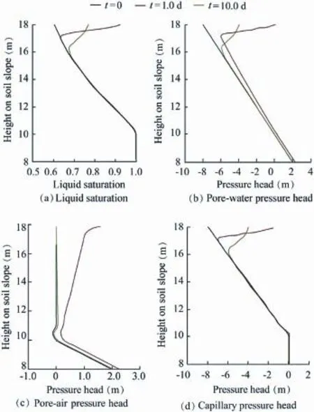
Fig.5.Simulation results of moisture and pressure prof i les at section A-A.
The simulated temporal changes of the pore-air,pore-water, and capillary pressure heads at observation point B are shown in Fig.6(a).The capillary pressure head increases during rainfall, indicating that the wetting front reaches point B and the saturation at point B increases,and the capillary pressure head decreases after the rainfall stops,because of the decreasing saturation due to the evaporation.The pore-air pressure head increases from an initial zero value to a maximum value at t=1.0 d,subsequently decreases sharply,and then gradually decreases to zero.The pore-water pressure head varies in a way similar to the way the capillary pressure head does,and it shows positive values during the period from t=0.76 d to t=1.1 d, indicating that soil is in a quasi-saturated state at point B(i.e., the pore-air pressure is greater than the matric suction). Fig.6(a)also demonstrates the simulated temporal changes of the vertical and horizontal air velocities at point B.It is noted that the negative velocity in the horizontal and vertical directions represents the air flowing rightward and downward, respectively.As soon as the rainfall begins,the air is first driven into the soil due to the rainfall inf i ltration.The absolute value of the vertical air velocity decreases gradually during the period from t=0 to t=0.4 d.This is because the rainfall intensity is not suff i cient to seal the slope surface,and the air inside soil is connected to the atmosphere.During this period from t=0 to t=0.4 d,the pore-air pressure head at point B remains substantially unchanged.Afterwards,with more rainwater inf i ltrating the soil,it is diff i cult for air to escape to the atmosphere due to the greater saturation in the surface soils,and the absolute value of the vertical downward air velocity increases gradually and reaches the maximum value at t=0.7 d,causing the pore-air pressure to increase rapidly.Then,the absolute value of the vertical air velocity begins to decrease due to the restriction of the groundwater table,and the pore-air pressure head increases slowly.As the rainfall stops,air flows upward and can escape from the soil,and the pore-air pressure head decreases signif i cantly to nearly zero.The vertical airflow is reversed at about t=1.05 d,which does not correspond to the time when the rainfall stops,indicating that air is still pushed into the soil by the advance of the wetting front soon after the rainfall stops.Meanwhile,the horizontal air velocity changes little because point B is near to the slope surface.
The simulated temporal changes of the pore-air,porewater,and capillary pressure heads,and those of the vertical and horizontal air velocities at observation point C are shown in Fig.6(b).The capillary pressure head retains its initial value throughout the inf i ltration event,indicating that point C is below the wetting front and the soil saturation at point C remains the same as that in the initial conditions.The pore-air pressure head increases from an initial zero value to a maximum value at t=1.63 d,and then decreases slowly to zero.The pore-water pressure head varies in a way similar to the way the pore-air pressure head does.The peak values of the pore-air and pore-water pressure heads occur at t=1.63 d (i.e.,0.63 d after the rainfall stops),indicating again that the wetting front continues to move downward even after the rainfall stops.The vertical airflow reversal time at point C,at t=2.0 d,is later than that at point B,which may be because point B is closer to the ground surface,and the air can escape from the surface more quickly.Thus,the pore-air pressure at point C reaches the maximum value at t=1.63 d,later than at point B.

Fig.6.Time evolutions of pressure heads and air velocities at two observation points.
The pore-water pressure head distribution of the slope prof i le at t=1.0 d is presented in Fig.7(a).In the wetted zone,the absolute value of the negative pore-water pressure head decreases signif i cantly compared with the initial value, and the pore-water pressure head near the ground surface is greater than zero,indicating that the soil near the ground surface has been saturated.The pore-air pressure head distribution of the slope prof i le at t=1.0 d is presented in Fig.7(b).The pore-air pressure head is greater than zero in the unsaturated zone and the value has an increasing trend towards the ground surface.
5.2.2.Analysis of stress field variations
The time evolutions of the normal stress and the net normal stress at point B on the given slip surface are shown in Fig.8(a). It should be noted that a positive pressure value indicates compression,and a negative value indicates tension,which is opposite to the sign conventions used in FLAC3D.The normal stressvariesverylittleintheperiodfromt=0tot=0.86d,and then increases to its highest value at t=1.0 d.After that,it decreasesalittletoasteadyvaluebecauseofthevariationofthe difference between the volumetric strain increment and the shear strain increment(i.e.,Si=3v-3s)at point B,as shown in Fig.8(b).Thevariationtrendofthenetnormalstressisopposite to that of the pore-air pressure(Figs.6(a)and 8(a)).It is noted that the value of the net normal stress is negative in the period from t=0.62 d to t=1.03 d,due to the pore-air pressure being higher than the normal stress.The time evolution of the ratio of the shear strength to the mobilized shear stress(τf/τi)at point B is also shown in Fig.8(a).It decreases first,and then increases, indicating that the safety at point B decreases due to rainwater inf i ltration.Siat point B shown in Fig.8(b)has positive values and changes little at first,but sharply increases to a high value when the rainfall stops,and then remains a steady value.The variationoftheporosityincrement atpointBissimilartothatof Sibecause of the positive correlation between the two(Eq.(2)). The occurrence of a positive porosity increment means that the porosity at point B(on the slope surface)increases due to rainwater inf i ltration.Fig.8(c)shows the time evolutions of the normal stress,net normal stress,and ratio(τf/τi)at point C.The variations of the net normal stress and the ratio(τf/τi)at point C are similar to those at point B,with the main difference being that the minimum net normal stress at point C occurs later than at point B.This is because of the delayed response of the poreair pressure at point C.The change of the normal stress at point C is also different from that at point B.The normal stress at point C changes little at first,and then decreases to a relatively stable value.Afterwards,it increases again to a steady value, similarly to the trend of Si(the negative value)as shown in Fig.8(d).Actually,Sichanges little at point C,due to the very small order of magnitude of 10-5.The variation of the porosity increment at point C shown in Fig.8(d)is also the same as that of Si(Eq.(2)),and its value is negative,indicating that the porosity decreases due to the compaction.It is noted that the porosity increments are the changes in porosity from the zero stress state,rather than from the gravitational loading equilibrium state,so the effects of the gravitation loading and rainfall inf i ltration on the porosity increments are included.

Fig.7.Distributions of pore-water and pore-air pressure heads at t=1.0 d(units:m).
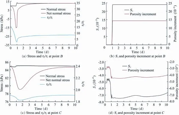
Fig.8.Time evolutions of normal stress,net normal stress,τf/τi,Si,and porosity increments at points B and C.
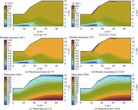
Fig.9.Distributions of Si,porosity increment,and mean stress at t=0 and t=1.0 d.
Figs.9(a)and(b)show the Sidistributions at t=0 and t=1.0 d,respectively.Figs.9(c)and(d)show the porosity increment distributions at t=0 and t=1.0 d,respectively.The distributions of the porosity increment at t=0 and t=1.0 d are similar to those of Si.The porosity increment at t=0 decreases with the increase of depth of the soil slope,due to the gravitationalloading.Whentherainfallstops,theporosityincrementin the slope surface exhibits a positive value,indicating that theporosity increases due to the effects of rainwater scouring,and the porosity deeper in the slope further decreases due to the compaction.Figs.9(e)and(f)show the mean stress((σ1+σ3)/2) distributions at t=0 and t=1.0 d,where σ1and σ3are the first and the third principle stress,respectively.Overall,compared withthemean stressatt=0,themean stressthroughout thesoil at t=1.0 d changes little,while the mean stress near the slope surfaceatt=1.0dincreasesduetotheriseofmoisturecontentin unit weight resulting from rainfall inf i ltration.
5.3.Slope stability analysis
In this study,the safety factor for the given slip surface was calculated according to Eqs.(9),(11)and(13),in which the seepage and stress fields obtained through the liquid-gas-solid three-phasecouplingmodelwereutilized.Thetimeevolutionof the safety factor for the given slip surface with the rainfall intensity of 5 mm/h is shown in Fig.10,where Fsis the safety factor obtained with Eq.(11).To analyze the contribution of different pressures,we introduce three safety factors for different cases:Fs1is the safety factor for the case that does not take into account the pore-air pressure(the pore-air pressure in Eqs.(9),(12)and(13)is set to zero),Fs2is the safety factor for the case that does not take into account the matric suction(the term(pg-pl)inEq.(9)issettozero),andFs3isthesafetyfactor forthe case inwhich neither thepore-airpressure northematric suction is taken into account(both the pore-air pressure and matric suction in Eqs.(9),(12)and(13)are set to zero).In Fig.10,FsandFs2decreaseintheperiodfromt=0tot=0.25d, increaseintheperiodfromt=0.25dtot=0.35d,thendecrease until t=1.0 d,and subsequently suddenly rise.After that,they decrease to its lowest value at t=1.5 d,and f i nally increase slowly to a steady value.The minimum safety factor does not occur when the rainfall stops,indicating a delayed effect of the safetyfactor.Fs1andFs3remainconstantintheperiodfromt=0 to t=0.25 d,increase in the period from t=0.25 d to t=1.0 d, and decrease to steady values afterwards.Overall,when the pore-air pressure is not considered,Fs1is greater than Fs,indicating that the pore-air pressure induced by the rainfall is unfavorable to slope stability.For the case without the matric suction,Fs2issmaller than Fs,indicatingthat thematric suction is benef i cial to slope stability.
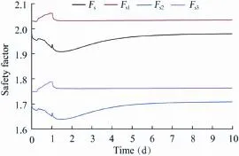
Fig.10.Time evolution of safety factor for different cases.
Fig.11 shows the time evolutions of the total sliding resistance force (Fsr=∫ΓτfdΓ) and total sliding force(Fst=∫ΓτidΓ)acting on the given slip surface.They are obtained by summing the shear strength and the mobilized shear stress at each point of the given slip surface,respectively.Fstremains almost constant first,and then decreases to a value before the rainfall stops,subsequently rebounds a little,afterwards suddenly decreases to its lowest value at t=1.0 d,and fi nally increases to a steady value.Fsris a combination of the total net normal stress and total matric suction(Eq.(9)).Fsrdecreases in the period from t=0 to t=1.0 d,subsequently suddenly increases,soon afterwards decreases to a relatively lower value at t=1.5 d,and f i nally increases to a steady value. ThevariationofFsistheresultofthevariationoftheratioofFsrtoFst(Eq.(11)).TheoveralltrendofFsisconsistentwiththatof Fsr,while the increase of Fsduring rainfall is mainly caused by the change in Fst.

Fig.11.Time evolutions of total sliding resistance force and total sliding force acting on given slip surface.
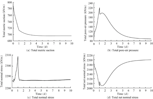
Fig.12.Time evolutions of total matric suction,total pore-air pressure,total normal stress,and total net normal stress acting on given slip surface.
Fig.12 shows the time evolution of the total matric suction (Ps),totalpore-airpressure(Pa),totalnormalstress,andtotalnet normal stress.During the inf i ltration process,Psdecreases to a steady value.Paincreases until the rainfall stops,subsequently suddenly decreases,soon afterwards increases to a higher value att=1.5d,andf i nallydecreasestoasteadyvalue.Thevariation of the total normal stress caused by the change in Si(Figs.9(a) and(b))is similar to those of Fs1and Fs3,indicating that the increaseinFs1andFs3att=0.25discausedbythetotalnormal stress(the effective cohesion remains constant throughout the process).The total net normal stress(σ*n=σn-pg)is a combination of the total normal stress and total pore-air pressure. Thus,the curve of the total net normal stress shows mainly a tendency opposite to the total pore-air pressure except for the time when the lowest value occurs.The variations of Fsand Fs2are mainly caused by the total net normal stress.As the rainfall intensity(1.38×10⁻⁶m/s)is larger than the hydraulic conductivity(1.0×10⁻⁶m/s),the rainfall inf i ltrates the soil at the rate of the hydraulic conductivity and ponding occurs on the groundsurface,sotheairinthesoilcannotescapefromtheslope surface and increases due to air compression.When the rainfall stops,the air in the soil can escape to the atmosphere suddenly due to the increasing porosity(Fig.9(d))of the slope surface. Thus,a sudden decrease in the pore-air pressure appears,which explains the sudden change in Fsand Fs2.Therefore,the variations of the safety factor for thegiven slip surface are caused by the combined effects of the total matric suction,total pore-air pressure,total normal stress,and total net normal stress.
6.Conclusions
In this study,a loosely coupled liquid-gas-solid three-phase model was employed to investigate the characteristics of seepage and stress field variations induced by rainfall inf i ltration with consideration of the effects of airflow and soil deformation,and the soil slope stability was estimated using both the simulated seepage and stress fields.As rainwater inf i ltrates the soil,the air is pushed into the soil and compressed by the advancing wetting front,and the pore-air pressure in the unsaturated zone increases.When the airflow is reversed because the rain stops,the pore-air pressure decreases until it approaches zero.The matric suction is benef i cial to slope stability,while the pore-air pressure is unfavorable to slope stability.The safety factor for a given slip surface decreases first,and then increases due to an increase in the normal stress.Later,the safety factor begins to decrease until the rainfall stops,and then a sudden rise occurs(caused by a sudden decrease in the pore-air pressure).After that,the safety factor decreases continually due to a decrease in the net normal stress and reaches its lowest value.Finally,it increases slowly to a steady value.The lowest value does not occur when the rainfall stops,indicating a delayed effect of the safety factor.The variations of the safety factor for the given slip surface are caused by a combination of the pore-air pressure,matric suction,normal stress,and net normal stress.
This study was conducted in order to improve our understanding of the effects of airflow and soil deformation on soil slope stability,rather than to provide a procedure to be adopted routinely in practical situations for present use.Therefore,a fi xed given slip surface,rather than a potential failure surface, was used to analyze the slope stability.During an actual in fi ltration event,the distributions of the pore-air pressure and the capillary pressure change continuously,so the critical slip surface is moving constantly.
Bary,B.,2002.Coupled hydro-mechanical and damage model for concrete as an unsaturated porous medium.In:Proceedings of the 15th ASCE Engineering Mechanical Conference.Columbia University,New York,pp.1—8.
Brooks,R.H.,Corey,A.T.,1966.Properties of porous media affecting fl uid flow.J.Irrig.Drain.Div.92(2),61—90.http://dx.doi.org/10.1061/ JRCEA4.0000424.
Chapuis,R.P.,Aubertin,M.,2003.On the use of the Kozeny-Carman equation to predict the hydraulic conductivity of soils.Can.Geotech.J.40(3), 616—628.http://dx.doi.org/10.1139/T03-013.
Cheng,Y.M.,Lansivaara,T.,Wei,W.B.,2007.Two-dimensional slope stability analysis by limit equilibrium and strength reduction methods. Comput.Geotech.34(3),137—150.http://dx.doi.org/10.1016/j.compgeo. 2006.10.011.
Cho,S.E.,Lee,S.R.,2001.Instability of unsaturated soil slopes due to inf i ltration.Comput.Geotech.28(3),185—208.http://dx.doi.org/10.1016/ S0266-352X(00)00027-6.
Collins,B.D.,Znidarcic,D.,2004.Stability analyses of rainfall induced landslides.J.Geotech.Geoenviron.Eng.130(4),362—372.http:// dx.doi.org/10.1061/(ASCE)1090-0241(2004)130:4(362).
Corey,A.T.,1954.The interrelation between gas and oil relative permeabilities.Prod.Mon.19(1),38—41.
Coussy,O.,1995.Mechanics of Porous Continua.Wiley,New York.
Ehlers,W.,Graf,T.,Ammann,M.,2004.Deformation and localization analysis of partially saturated soil.Comput.Methods Appl.Mech.Eng. 193(27),2885—2910.http://dx.doi.org/10.1016/j.cma.2003.09.026.
Fredlund,D.G.,Morgenstern,N.R.,Widger,R.A.,1978.The shear strength of unsaturated soils.Can.Geotech.J.15(3),313—321.http://dx.doi.org/ 10.1139/t78-029.
Fredlund,D.G.,Xing,A.Q.,Fredlund,M.D.,Barbour,S.L.,1996.The relationship of the unsaturated soil shear strength to the soil-water characteristic curve.Can.Geotech.J.33(3),440—448.http://dx.doi.org/10.1139/ t96-065.
Gawin,D.,Baggio,P.,Schref l er,B.A.,1995.Coupled heat,water and gas flow in deformable porous media.Int.J.Numer.Methods Fluids 20(8—9), 969—987.http://dx.doi.org/10.1002/f l d.1650200817.
Gawin,D.,Schref l er,B.A.,Galindo,M.,1996.Thermo-hydro-mechanical analysis of partially saturated porous materials.Eng.Comput.13(7), 113—143.http://dx.doi.org/10.1108/02644409610151584.
Guo,H.,Jiao,J.J.,Weeks,E.P.,2008.Rain-induced subsurface airflow and Lisse effect.Water Resour.Res.44(7),W07409.http://dx.doi.org/10.1029/ 2007WR006294.
Hu,R.,Chen,Y.F.,Zhou,C.B.,2011.Modeling of coupled deformation,water flow and gas transport in soil slopes subjected to rain in fi ltration.Sci. China Technol.Sci.54(10),2561—2575.http://dx.doi.org/10.1007/s11431-011-4504-z.
Itasca Consulting Group Inc.(ICGI),2002.Fast Lagrangian Analysis of Continua in 3 Dimensions Version 2.10,User's Manual.Itasca Consulting Group Inc.,Minneapolis.
Kuang,X.X.,Jiao,J.J.,Li,H.L.,2013.Review on air flow in unsaturated zones induced by natural forcings.Water Resour.Res.49(10),6137—6165. http://dx.doi.org/10.1002/wrcr.20416.
Leverett,M.C.,1941.Capillary behavior in porous solids.Trans.AIME 142(1),152—168.http://dx.doi.org/10.2118/941152-G.
Lewis,R.W.,Schre fl er,B.A.,1987.The Finite Element Method in the Deformation and Consolidation of Porous Media.John Wiley and Sons, New York.
Liakopoulos,A.C.,1965.Transient Flow Through Unsaturated Porous Media. Ph.D.Dissertation.University of California,Berkeley.
Mualem,Y.,1976.A new model for predicting the hydraulic conductivity of unsaturated porous media.Water Resour.Res.12(3),513—522.http:// dx.doi.org/10.1029/WR012i003p00513.
Nagel,F.,Meschke,G.,2010.An elasto-plastic three phase model for partially saturated soil for the finite element simulation of compressed air support in tunnelling.Int.J.Numer.Anal.Methods Geomech.34(6),605—625.http:// dx.doi.org/10.1002/nag.828.
¨Oberg,A.L.,S¨allfors,G.,1997.Determination of shear strength parameters of unsaturated silts and sands based on the water retention curve.ASTM Geotech.Test.J.20(1),40—48.http://dx.doi.org/10.1520/GTJ11419J.
Pruess,K.,Oldenburg,C.,Moridis,G.,1999.TOUGH2 User's Guide,Version 2.0,Earth Science Division.Lawrence Berkeley National Laboratory, University of California,Berkeley.
Regmi,R.K.,Nakagawa,H.,Kawaike,K.,Baba,Y.,Zhang,H.,2010.Two and Three Dimensional Slope Stability Analysis of Landslide Dam Failure Due to Sliding.Annuals Disaster Prevention Research Institute,Kyoto University,pp.617—627.
Rutqvist,J.,Wu,Y.S.,Tsang,C.F.,Bodvarsson,G.,2002.A modeling approach for analysis of coupled multiphase fluid flow,heat transfer,and deformation in fractured porous rock.Int.J.Rock Mech.Min.Sci.39(4), 429—442.http://dx.doi.org/10.1016/S1365-1609(02)00022-9.
Sako,K.,Danjo,T.,Fukagawa,R.,Bui,H.H.,2011.Measurement of porewater and pore-air pressure in unsaturated soil.In:Proceeding of 5th Asia-Pacif i c Conference on Unsaturated Soils.Kasetsart University,Pattaya,pp.443—448.
Schref l er,B.A.,Zhan,X.Y.,1993.A fully coupled model for water flow and airflow in deformable porous media.Water Resour.Res.29(1),155—167. http://dx.doi.org/10.1029/92WR01737.
Schref l er,B.A.,Scotta,R.,2001.A fully coupled dynamic model for twophase fluid flow in deformable porous media.Comput.Methods Appl. Mech.Eng.190(24),3223—3246.http://dx.doi.org/10.1016/S0045-7825(00)00390-X.
Sun,D.M.,Zhu,Y.M.,Zhang,M.J.,2007.Water-air two-phase flow model for numerical analysis of rainfall inf i ltration.J.Hydraul.Eng.38(2),150—156. http://dx.doi.org/10.3321/j.issn:0559-9350.2007.02.004.
Sun,D.M.,Feng,P.,Zhang,M.J.,2009.Ref i ned analysis of stability of unsaturated soil slope due to rainfall inf i ltration considering the effect of gas phase.J.Tianjin Univ.42(9),777—783.http://dx.doi.org/10.3969/ j.issn.0493-2137.2009.09.004(in Chinese).
Sun,D.M.,Zang,Y.G.,Semprich,S.,2015.Effects of airflow induced by rainfall inf i ltration on unsaturated soil slope stability.Transp.Porous Media 107(3),821—841.http://dx.doi.org/10.1007/s11242-015-0469-x.
van Genuchten,M.T.,1980.A closed-form equation for predicting the hydraulic conductivity of unsaturated soils.Soil Sci.Soc.Am.J.44(5), 892—898.http://dx.doi.org/10.2136/sssaj1980.03615995004400050002x.
Vanapalli,S.K.,Fredlund,D.G.,Pufahl,D.E.,Clifton,A.W.,1996.Model for the prediction of shear strength with respect to soil suction.Can.Geotech. J.33(3),379—392.http://dx.doi.org/10.1139/t96-060.
Wang,Z.,Feyen,J.,Genuchten,M.T.,Donald,R.N.,1998.Air entrapment effects on inf i ltration rate and flow instability.Water Resour.Res.34(2), 213—222.http://dx.doi.org/10.1029/97WR02804.
Xu,Y.B.,Wei,C.F.,Li,H.,Chen,H.,2009.Finite element analysis of coupling seepage and deformation in unsaturated soils.Rock Soil Mech.30(5), 1490—1497.http://dx.doi.org/10.3969/j.issn.1000-7598.2009.05.053 (in Chinese).
Received 13 October 2015;accepted 20 June 2016
This work was supported by the National Natural Science Foundation of China(Grants No.51579170 and 51179118)and the Science Fund for Creative Research Groups of the National Natural Science Foundation of China (Grant No.51321065).
*Corresponding author.
E-mail address:sundongmei@126.com(Dong-mei Sun).
Peer review under responsibility of Hohai University.
http://dx.doi.org/10.1016/j.wse.2016.06.008
1674-2370/©2016 Hohai University.Production and hosting by Elsevier B.V.This is an open access article under the CC BY-NC-ND license(http:// creativecommons.org/licenses/by-nc-nd/4.0/).
©2016 Hohai University.Production and hosting by Elsevier B.V.This is an open access article under the CC BY-NC-ND license(http:// creativecommons.org/licenses/by-nc-nd/4.0/).
 Water Science and Engineering2016年3期
- Water Science and Engineering的其它文章
- Numerical analysis of rapid drawdown:Applications in real cases
- Seismic responses of high concrete face rockfill dams:A case study
- Numerical simulation of seismic damage and cracking of concrete slabs of high concrete face rockfill dams
- Design considerations and behavior of reinforced concrete core dams during construction and impounding
- Numerical stress-deformation analysis of cut-off wall in clay-core rockfill dam on thick overburden
- Calibration and performance of two different constitutive models for rockfill materials
