Resistance SPot Welding Method for Metal-Based Fiber Bragg Grating Sensors
Zhang Tao(张涛),Wei Pengyu(韦朋余),Yue Yalin(岳亚霖)*
China Ship Scientific Research Center,Wuxi 214082,P.R.China
Resistance SPot Welding Method for Metal-Based Fiber Bragg Grating Sensors
Zhang Tao(张涛),Wei Pengyu(韦朋余),Yue Yalin(岳亚霖)*
China Ship Scientific Research Center,Wuxi 214082,P.R.China
Aiming at the requirements of installation and work environment of metal-based fiber Bragg grating(EBG)sensor,a resistance spot welding method is presented.Eirstly,the effect of welding parameters on welding quality is discussed theoretically,and a suitable resistance spot welding method for the metal-based EBG sensor is proposed for the first time.Then through serial resistance spot welding tests,the feasibility and practicability of the method are verified,and optimal welding parameters for two different tested metals are obtained.Eatigue performance test validates EBG sensors installed by the proposed method with good fatigue properties and long-term stable measurement performance.The research results can provide technical guidance for engineering structure long-term safety monitoring.
fiber Bragg grating(EBG)sensor;resistance spot welding;parametric optimization
0 Introduction
Structural health monitoring(SHM)[1]is one of the most critical technologies in engineering,involving continuous monitoring,diagnosis and damage identification of engineering structures. Its ultimate aim is to reflect the structure health status,take appropriate maintenance measures to keep the reliability,reduce the maintenance cost and extend the service life of the structures[2]. With its fast development fiber Bragg grating EBG sensors has been largely used to provide early risk warning and damage assessment of modern engineering structures[3].With advantages of high accuracy,anti-corrosion,anti-interference,long-term good stability and distributed sensing[4],etc.,EBG sensor is suitable for long-term monitoring in harsh environments,and becomes one of the most promising sensors[5].
Metal sheet base is the most common form for EBG packaging,and there are three major installation methods for metal-based EBG sensors[6]:Pasting,riveting and resistance spot welding.Under the influence of external environment such as high temperature,humidity and high frequency vibration,pasting is not stable in a long-term measurement,because it may reduce the transmission efficiency of EBG sensors and make it difficult to meet the measurement requirements[7].Riveting requires opening holes on the surface of the measured structure,which damages the original structure and is often hard to accept.Resistance spot welding,on the contrary,with advantages of high mechanical strength,accurate strain transfer and no damage on original structure,etc.,is an ideal installation method for metal-based EBG sensor.
At present,spot welding installation method for metal-based EBG sensor has not been drawn enough attention,and there are limited researches on it.In practical applications,the following problems often arise.Eirst,excessive releasedwelding heat may damage EBG sensors during the instantaneous welding process,resulting in low survival rate of installed sensors.Second,welding quality of surviving EBG sensors is poor,which leads to problems such as bad strain transfer performance,short service life,or even failure of the sensor.
To solve these problems,resistance spot welding method for metal-based EBG sensors is studied according to requirements of installation and work environment.Eirstly,the effect of welding parameters on weld quality is deduced theoretically,and a suitable resistance spot welding method for the metal-based EBG sensor is proposed.Then the feasibility and practicability of the proposed method is verified through serial resistance spot welding tests,and optimal welding parameters are obtained.On this basis,fatigue properties of EBG sensors installed by resistance spot welding is tested via the fatigue performance verification test.All these works will provide technical support for long-term SHM using EBG sensors.
1 Resistance SPot Welding Method for Metal-Based FBG Sensor
1.1 Theory for resistance sPot welding
Metal-based EBG sensor includes two parts,metal sheet base and EBG.Metal sheet bases used in this paper are made of stainless steel,whose shape has been maximum elastic designed[8],as shown in Eig.1.Both ends of EBG are stuck in the groove of the reverse side,and four weld holes are equipped on the positive side.Welding at the center of the hole can fix the base on the surface of the measured structure.

Eig.1 Structure of metal-based EBG sensor
The internal structure of spot welder can be simplified to a large power transformer,as shown in Eig.2,turning 220 V AC frequency power into a low voltage and high current power by inductive principle.The output voltage can also be set by adjusting magnetic induction coil[9].
During the spot welding process,current circuit will be generated between the two electrodes. Since there is contact resistance on the surface between EBG sensor base and measured structure[10],a massive source of resistance heat will be generated on the surface,melting the metal in central heating region into high temperature plastic or molten state,as shown in Eig.3.When the nugget is solidified by cooling,rigid connection points will form on the surface,which can fix the metal-based EBG sensor on measured structure.
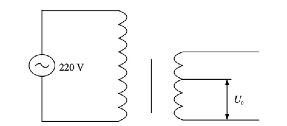
Eig.2 Internal structure of spot welder

Eig.3 Resistance spot welding process
1.2 Effects of welding Parameters on resistance sPot welding quality
The heat release of resistance spot welding must follow the Joule′s law

where Q(t)is the quantity of released resistance welding heat;i(t)the electric current for spot welding;r(t)the contact resistance of the surface;and t the welding time.Since the contactsurface is rough on a micro-level,and metal resistance is changing with temperature,the contact resistance r(t)is a dynamic changing value[11].Therefore,i(t)is function of t too.i(t)can be replaced by

where R(t)is the resistance between the electrodes;U0the output voltage between two electrodes,which is a fixed value set by the spot welder.Thus the released resistance heat can be controlled by U0and t.
1.2.1 Effects of output voltage on heat release Erom Eq.(2),a relatively higher output voltage will produce a relatively larger electric current,which will generate more welding heat per unit time by Joule′s law.In contrast,the lower the output voltage is,the smaller the electric current is,and less heat is generated per unit time.Therefore,the amount of heat release in per unit time depends on welder′s output voltage as shown in Eig.4,where Q is the amount of heat release,Qsthe critical heat to spray,and Qmthe critical heat to melt.

Eig.4 Relationship between welding parameters and heat release
1.2.2 Effects of welding time on heat release
As shown in Eig.4,set tminas the beginning time of generating weld nuggets,and tmaxthe critical time to spray.The relationship between weld quality and welding time is demonstrated as follows:
When t<tmin,it is still in the heating process.The amount of resistance welding heat is not enough to form weld nuggets,or the nuggets size is too small to fix the metal-base on the surface.
When tmin<t<tmax,weld nuggets will be generated in this stage,and their size will grow larger along with welding time.As the nuggets cools down and solidifies,there will be several rigid connection points between EBG sensor base and the measured structure.
When t>tmax,the nuggets have already reached their limited size,keeping charging may lead to spray phenomena and the excessive welding heat will damage the fiber under the metalbase.When broken nuggets cool down and solidify,it will form an inhomogeneous stress field,making the EBG sensor subject to an initial compression or tensile force.This situation may severely weaken EBG sensor′s sensing properties and connection performance.
1.3 Resistance sPot welding method for metalbased FBG sensor
The EBG metal-base is made extremely thin without affecting the overall sensor strain transfer performance,so the base can be easily melt through and the fiber may be fused by the excessive welding heat.Different from the common spot welding method which is only for establishing permanent connection purpose,resistance spot welding method for metal-based EBG sensor focuses on the requirements of welding object,process and inspection after welding,in order to control the welding quality to ensure that the sensor cannot be damaged during welding process and its mechanical properties can meet the measurement requirements after welding.
1.3.1 Welding object
Generating suitable size of nuggets is related not only to the heat release of spot welding,but also to the dissipating capability of the welding object—the measured metal structure.Eor metal with high electrical resistivity and low heat dissipating capability,welding time for generating nuggets is short,while for metal with low electrical resistivity and high heat dissipating capability,the welding time is longer.Therefore,the suitable parameters of welding metal-based EBG sensors on different kinds of metal structures are not consistent.
1.3.2 Welding process
During the welding process,the choice of electrode size,electrode pressure and welding parameters has influence on the welding quality of metal-based EBG sensor.Electrode size and electrode pressure will change the resistance between the electrodes,thus change the output welding heat quantity per unit time.
In previous studies,researches have been carried out for electrode size and electrode pressure effect on welding quality of metal-based EBG.The copper electrode has been adopted because of its high temperature strength and abrasion hardness.The size is recommended as shown in Eig.5,with small current density,good heat conducting properties,and stable resistance heat output,as well as better formed joint quality. Eurther,since the metal-base is very thin,the request of electrode pressure is not high,so as to ensure the base be compressed on the measured structure when using the handed spot welder.As it is very difficult to control welding heat by managing resistance between the electrodes,effects of output voltage and welding time on resistance spot welding quality are emphatically analyzed.
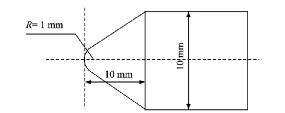
Eig.5 Electrode size
According to the analysis of effect law between welding parameters and welding quality,the released heat of resistance spot welding can be controlled by the welder′s output voltage and welding time,the speed of heat release by the welder′s output voltage and welding quality by welding time.Under a certain output voltage, there is a specific time range for welding metalbased EBG sensors on different metal structures. The welder′s output voltage is chosen according to the thickness of EBG base,and the welding time is determined by a special time interval,which can be obtained by serial resistance spot welding tests.
1.3.3 Inspection after welding
Spectrum detector and infrared transmitter can contribute to check whether the welded EBG sensors function well after welding.If the number of detected wave peak is consistent with the number of EBG sensor,connect the fiber link to spectrum detector,which can prove that all the EBG sensors are survived.If not,launch infrared at the import end,the damaged fiber ports can be found by the naked eye(Eig.6).
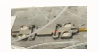
Eig.6 Damaged fiber port
When welding nuggets cool solidified,the tangential component of the welding fixed force will make EBG sensor subject to an initial tensile or compression force,which will change the EBG sensor central wavelength thus affects the EBG sensors effective range and fatigue life.Therefore,the influence of spot welding on the EBG sensor can be quantified by central wavelength shift value when checking whether the welded sensor′s properties can meet the measurement requirements,in addition to conventional indicators like linearity,repeatability,uncertainty and so on.
2 Resistance SPot Welding Tests
To determine the welding parameters forwelding metal-based EBG sensor on different metal structures,two different high-strength steels have been chosen to conduct the resistance welding test:Steel A(yield limit of 500 MPa)and steel B(yield limit of 600 MPa).DN-5 welder is adopted in this test.D represents spot welding machine and N represents power frequency,which are suitable for the thickness of 0.2—2 mm.It has two different output voltages,3.8 and 1.8 V,and the welding time ranges from 1 to 11 circles(1 circle equals to 20 ms).Compared to the specimen,the thickness of EBG sensor base can be ignored,so the effect of specimen′s thickness is not concerned here.
2.1 Welding quality tests
When welding parameters set at 1.8 V and 11 circles on steel A,the base cannot be penetrated,which reveals that the released heat is not enough to generate nuggets when output voltage set at 1.8 V,so the following output voltage is 3.8 V.
When t=1 circle,EBG sensor base can be easily stripped from the surface,and there are only two fuzzy weld spots can be observed on the back of the base,as shown in Eig.7,which means the base is incompletely penetrated and the welding heat is not enough to generate nuggets.
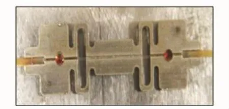
Eig.7 t=1 circle
When t=2—3 circles,the heating process is smooth without sparkling,as shown in Eig.8,and the welded EBG sensor is firmly fixed to the surface(Eig.9).
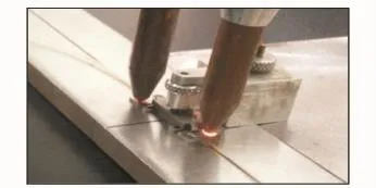
Eig.8 Heating process when t=2—3 circles

Eig.9 Installing effect when t=2—3 circles
When t=4 circles,most EBG sensors are checked to be damaged by an infrared transmitter,and a few of them are survived.Eor the damaged ones,welding process is accompanied with light splash,and the welding points size is overlarge in disperse shape(Eig.10).Strip down the broken EBG sensors,welding spot are found too close to the damaged end(Eig.11),which reveals that the released welding heat is excessive.

Eig.10 Welding points when t=4 circles
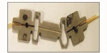
Eig.11 Damaged end when t=4 circles
As a consequence,the time interval for welding metal-based EBG sensor on steel A rangesfrom 2 to 3 circles.Using the same method and process,the time interval for welding metalbased EBG sensor on steel B is from 3 to 4 circles.
2.2 Performance tests for resistance sPot welding
Central wavelength value is one of the most basic performance parameters.All the central wavelength shift values of welded EBG sensors are shown in Table 1,the longer the welding time is,the bigger the wavelength shift value is. Therefore,considering the effect on the EBG sensor′s properties,welding time should be as short as possible within the determined time interval. Therefore,Tables 1,2 show that optimal welding time for welding metal-based EBG sensors on steel A and steel Bis 2 and 3 circles,respectively.

Table 2 Central wavelength shift value of welded FBG sensors on steel B
2.3 Fatigue Performance verification
To verify the fatigue strength of metal-based EBG sensor installed by resistance spot welding,fatigue performance verification is carried out. Two EBG sensors(EBG-01 and EBG-02)are welded on the specimen made of steel A,shown in Eig.12.Welding parameters and central wavelength shift value are shown in Table 3.The fatigue strain amplitude was-145—145με,and the tensile device is shown in Eig.13.The fatigue test is divided into 5 stages:Initial stage,50 000 cycles,100 000,200 000 and 300 000 cycles,and the frequency is 10 Hz.

Eig.12 EBG fatigue test
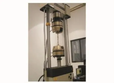
Eig.13 Tensile devices
The dynamic strain history curve of EBG-01 in initial stage and 300 000 cycles stage are shown in Eigs.14,15,respectively.It can be seen that the dynamic response performance and long-term monitoring stability of EBG sensors are both excellent during the whole fatigue test.The static tensile strain curve of two EBG sensors in the initial stage and 300 000 cycles stage are shown inEig.16.It is a linearity curve with good resilience,which indicates that the strain transformation between EBG sensors and the measured structure is stable during the whole fatigue test. Therefore,metal-based EBG sensors installed by resistance spot welding have good fatigue properties,thus can be used in long-term fatigue damage monitoring of structure.

Table 3 Welding Parameters and central wavelength shift value for FBG-01 and FBG-02

Eig.14 Dynamic strain history curve of EBG-01 in the initial stage

Eig.15 Dynamic strain history curve of EBG-01 in 300 000 cycles stage

Eig.16 Static tensile strain curves of two EBG sensors in the initial stage and 300 000 cycles stage
3 Conclusions
According to requirements in the installation process and features of the work environment of the EBG sensor,a specialized resistance spot welding method for metal-based EBG sensor is proposed for the first time.Then the feasibility and practicability of the proposed method are verified by serial resistance spot welding tests.Erom the tests result,conclusions can be drawn as follows:
The survival rate of welded EBG sensors can be controlled by welder′s output voltage and welding time,the speed of heat release by the welder′s output voltage and welding quality by welding time.
Generating suitable size of nuggets is determined by both the heat release of welding and the dissipating capacity of the measured metal,the welding time interval on different kinds of metal structures are not consistent.Considering the effect on the EBG sensor properties,under the voltage of 3.8 V,the optimal time for welding metal-based EBG sensors on steel A and steel B is 2 and 3 circles,respectively.
Metal-based EBG sensors installed by resistance spot welding have been proved with good fatigue properties and long-term stable measurement performance via the fatigue performance verification test.The research results can provide technical guidance for mounting EBG sensor in engineering structure long-term safety monitoring application.
[1] Wu Jing,Wu Hanpin,Huang Junbin,et al.Large range EBG sensor for ship structure health monitoring[J].Optics and Precision Engineering,2013,22(2):311-317.
[2] Rodrigues C,Cavadas E,Eélix C,et al.EBG based strain monitoring in the rehabilitation of a centenary metallic bridge[J].Engineering Structures,2012,44(6):281-290.
[3] Chen Yin,Wei Pengyu,Yue Yalin,et al.Research on ship structural health monitoring system based on EBG sensing technology[C]//Marine Steel Structure Branch Steel Construction Society 2014 ConferenceProceedings.Weihai:JSM,2014:567-572.
[4] Torres B,Payá-Zaforteza L,Calderón P A,et al.A-nalysis of the strain transfer in a new EBG sensor for structural health monitoring[J].Engineering Structures,2011,33(2):539-548.
[5] Erovel M,Del Olmo E,Torres J G,et al.Health monitoring of a weight efficient lattice spacecraft structural element with EBGS sensors[C]//6th European Workshop on Structural Health Monitoring. Spain:DGZEP,2012:7.
[6] Wnuk V P,Mendez A,Eerguson S,et al.Process for mounting and packaging of fiber bragg grating strain sensors for use in harsh environment applications[C]//Smart Structures Conference 2005.San Diego:SPIE,2005:5758-6-5758-13.
[7] Zhang Tao,Wei Pengyu,Yue Yalin,et al.Protection methods for EBG sensors on ship structure[C]// Marine Steel Structure Branch Steel Construction Society 2014 Conference Proceedings.Weihai:JSM,2014:527-536.
[8] Yuan Zilin,Gong Yuan,Ma Yaoyuan,et al.Structures optimization of fiber Bragg grating strain sensor[J].Acta Photonica Sinica,2012,41(11):1261-1266.
[9] Li Y,Lin Z,Lai X,et al.Induced electromagnetic stirring behavior in a resistance spot weld nugget[J]. Science China Technological Sciences,2010,53(5):1271-1277.
[10]Xu W,Chen D L,Liu L,et al.Microstructure and mechanical properties of weld-bonded and resistance spot welded magnesium-to-steel dissimilar joints[J]. Materials Science and Engineering:A,2012,537:11-24.
[11]Wu Pei,LüJiahang,Bay N.Measurement of dynamic resistance in resistance spot welding[J].China Welding,2007,16(4):42-46.
(Executive editor:Zhang Bei)
TP212;TG441 Document code:A Article ID:1005-1120(2015)03-0289-08
*CorresPonding author:Yue Yalin,Researcher,E-mail:yueyalin313@126.com.
How to cite this article:Zhang Tao,Wei Pengyu,Yue Yalin.Resistance spot welding method for metal-based fiber Bragg grating sensors[J].Trans.Nanjing U.Aero.Astro.,2015,32(3):289-296.
http://dx.doi.org/10.16356/j.1005-1120.2015.03.289
(Received 18 December 2014;revised 2 March 2015;accepted 24 April 2015)
 Transactions of Nanjing University of Aeronautics and Astronautics2015年3期
- Transactions of Nanjing University of Aeronautics and Astronautics的其它文章
- Two-Dimensional Modal Curvature for Damage Detection in Plates
- Performance ImProvement Method of CFRP with Embedded OPtical Fiber
- MorPhological Undecimated Wavelet DecomPosition Fusion Algorithm and Its APPlication on Fault Feature Extraction of Hydraulic PumP
- Construction of Crack Perturbation Model and Forward Semi-analytical Model of Attached Eddy Current Sensor
- RelationshiP Between Corrosion Level of Steel Bar and Diameter of Corroded Sensing Steel Wire in Wireless Sensor
- Data Fusion of MultiPle Curvature Mode ShaPes for Structural Damage Diagnosis
