Electrical Modeling of a Wireless Ultrasonic Power Transfer System
2015-06-24 06:23:52LeungHoFaiDaiXinHuAiguo
电工技术学报 2015年19期
Leung Ho Fai Dai Xin Hu Aiguo
(1.Department of Electrical and Computer Engineering The University of Auckland Auckland 1010 New Zealand
2.School of Automation Chongqing University Chongqing 400030 China)
0 Introduction
Wireless Power Transfer(WPT)becomes increasingly popular,offering improved safety and convenience for devices under hazardous and dirty environments.Ultrasonic Power Transfer(UPT),also known as Acoustic Energy Transfer(AET),is an emerging technology which utilizes ultrasound as the power transfer mechanism[1].
Existing WPT technologies such as Inductive Power Transfer(IPT)cannot transfer power throughmetal barriers by nature.On the contrary,there is no limitation on the coupling medium for UPT.Power can be transferred through air,fluid,and solid media[2-4].In fact,a UPT system performs best for power transfer through metal barriers,making it suiTablefor many applications such as powering sensors and devices in submarines,gas pipelines,and metal containers.
UPT is still at its early stage so there are many aspects that need to be explored in both theory and practice.In particular,there is a lack of research on theoretical modeling and analysis of power transfer characteristics.This paper presents a theoretical model of a UPT system by investigating its electrical circuit equivalence for predicting the system performance.The theoretical model is verified by practical experiments.
1 Basic Operating Principles
Fig.1 shows a simplified block diagram of a UPT system.It consists of a primary unit that generates a high frequency voltage source for driving a primary transducer,a coupling medium for ultrasonic coupling,a secondary power pickup transducer,and a pickup circuit for driving a load.The primary transducer converts the electrical energy into an ultrasonic wave.The generated wave propagates through the medium and the pickup transducer converts the acoustic energy into electricity.The received power is then processed to drive the load.The frequency of the sound wave produced is in the ultrasound region ofthe transducer,which can range from 20 kHz to 5 MHz level,hence it is ultrasonic and inaudible by human beings.

Fig.1 Block diagram of a typical UPT system
Piezoelectric materials are commonly used for both primary and pickup transducersbecause piezoelectric materials have high transduction efficiency[5].A special topology of piezoelectric transducers called Langevin Type transducers have been used in Ref.[2]where the UPT system demonstrated 1 kW of pulsed power transfer.The Langevin type transducer consists of several piezoelectric elements stacked on top of each other and held tightly by a compression bolt between a head and a tail mass.The compression bolt preloads the piezoelectric elements into compression to avoid fracture of the material when operating at high power[5].The transduction efficiency of piezoelectric materials is highestwhen operated at its resonant frequency.Fig.2 shows the lumped equivalent electrical model of the primary piezoelectric transducer,where the resonance is modeled by the series Lp,Cp,and Rp.Zmechmodels the mechanical interaction between the transducer and the coupling medium,Cstaticis the apparent capacitance across the piezoelectric,and Ytrans(f)is the admittance of the piezoelectric transducer.
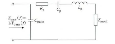
Fig.2 Lumped equivalent model of piezoelectric transducer
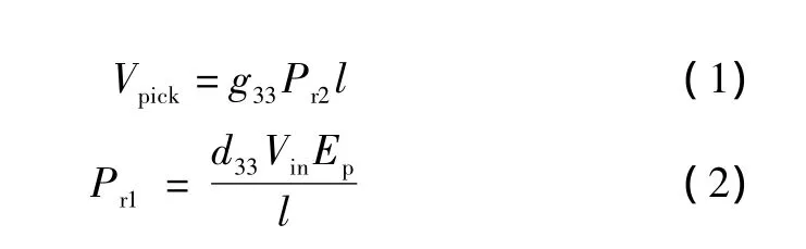
Constitutive piezoelectric equations can quantify the relationship between the applied electrical energy to output acoustic energy and,vice versa[6].Eq.(1)and Eq.(2)presentthe direct and indirect piezoelectric effect respectively,provided there is no external pressure or electric field applied on the piezoelectric material.Vpickis the voltage induced given an acoustic pressure of Pr2across the piezoelectric.Pr1is the excitation pressure exerted by the piezoelectric given an input voltage Vinacross the piezoelectric.d33and g33represent the piezoelectric constants,Eptheelasticconstant(ortheYoung’s modulus),and lthe thicknessofthe piezoelectric material.
2 System Modeling
The proposed theoretical model predicts the output characteristic of the system if the excitation voltage at the primary transducer and the admittance spectrum of the transducer are known.The model consists of two main parts:the primary transducer modeland the pickup model.The primary transducer model predicts the excitation pressure at the primary transducer first,then the pressure at the pickup transducer is estimated from the excitation pressure based on the acoustic coupling of the system.Finally,the pickup model predicts the output characteristics.
2.1 Primary Transducer Model
The constitutive piezoelectric equations predict the excitation pressure at the input side of the coupling medium if the voltage across the piezoelectric is given.However,it does not consider piezoelectric resonance.Thus,a multiplier factor is proposed to modify the constitutive equations based on the admittance spectrum ofthe piezoelectric transducer Ytrans,primary(f)when attached onto the coupling medium as shown in Eq.(3),where Yrefis the admittance of the piezoelectric at off resonance.The admittance spectrum maps the resonant properties of the piezoelectric in the equations.A detailed explanation of the multiplier factor has been presented in Ref.[7].

2.2 Pickup Model
The pickup pressure can be estimated using Eq.(4),where k represents the coupling coefficient between the coupling medium and the transducer.The greater the acoustic coupling between the transducer and coupling medium,the higher the coupling coefficient(0<k<1).The acoustic impedance matching is an important factor affecting the acoustic coupling,and more research will need tobeconducted toestablish an expression to accurately define the acoustic coupling k.
Fig.3 a illustrates the equivalent circuit of the pickup piezoelectric transducer.Vpickis the induced voltage that can be calculated using Eq.(1).Fig.3 b illustrates the pickup model after applying a Norton transformation.Note Cstaticis in parallel with Lp,Cp,Rp,and Zmechcan be replaced with the impedance of the transducer Ztrans(f)as illustrated in Fig.3 c.Finally,a Thevenin transformation is conducted to acquire the simplified pickup model Fig.3 d which can be used to predict the output characteristics.Eq.(5)and Eq.(6)show the equations for calculating the theoretical open circuit voltage and short circuit current respectively.


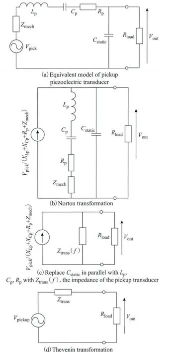
Fig.3 Equivalent circuit models
3 System Experimental Setup
Two SMBLTD45F28H Langevin Type transducers from Steiner& Martins,Inc.were used at both the primary and pickup sides of the UPT system.Their nominal resonant frequency is 28 kHz,rated at 70 W with a diameter of 45 mm.An aluminum plate measuring 350 mm×350 mm×5 mm was used as the coupling medium.The primary unit consists of aPAD108 power operational amplifier from Power Amp Design,a HP 33120A waveform generator,and a voltage step-up transformer,producing a sinusoidal voltage of40Vrmsacross the primary transducer.The admittance spectrum of the piezoelectric transducer measured from an Agilent E4980A Precision LCR meter is shown in Fig.4 and Yrefis selected at Ytrans(22 kHz).Table1 presents the system parameters.The system configuration is illustrated in Fig.5 ,and a photo of the setup is shown in Fig.6 .

Fig.4 Admittance spectrum of piezoelectric attached to aluminum coupling medium

Tab.1 Parameter values used in model

Fig.5 System configuration block diagram

Fig.6 Photo of the system setup
4 Theoretical and Experimental Results
The theoretical results calculated from the proposed models are compared with practical measurements.The output voltage and current characteristic curve is presented in Fig.7 ,the output power in Fig.8 ,and the admittance spectrum of the primary transducer plotted for different output load resistances in Fig.9 .

Fig.7 Output voltage vs.current plot

Fig.8 Output power plotted against load resistance

Fig.9 Admittance spectrum of piezoelectric transducer for various output load resistances
The theoretical model can predict the output characteristics fairly well,albeit some slight differences at certain loads.Although the UPT system is designed to operate at the resonant frequency of the transducers,the results do not correspond to the full compensation of pickup circuits,which may be caused partly by the change of the admittance spectrum of the system when the load resistance varies.
The output power spectrum with respect to the load resistance shown in Fig.8 indicates a local maximum output power around a resistance of 100 Ω.Fig.9 shows the peak of the admittance decreases as the load resistance increases,and the highest peak in admittance with the 100 Ω load.Therefore,the output power capability is partly dependent on the admittance of the piezoelectric transducer;the higher the admittance,the greater the power transfer capability.
To improve the power transfer capability for a UPT system,an electronic pickup circuitry needs to be implemented.The pickup circuit can be designed to provide an impedance optimalto the transducer,thus the transducer admittance presents a high peak for all electrical loads.Implementing such a pickup circuitry also helps to improve the output voltage-current characteristic curve.
5 Conclusion
A theoretical model in the form of equivalent circuits has been proposed to predict the output characteristics of a UPT system.A practical UPT system has been built to verify the proposed model,and it has found that the theoretical and practical results showing the system output characteristics are in a very good agreement.
The power transfer capability of a UPT system was found to be proportional to the admittance of the primary piezoelectric transducer.Thus to enhance the power transfer capability,the pickup compensation circuitcan be designed such that the electrical load observed by the transducer is always optimal for realizing a high admittance regardless of the load variations.
[1]Roes M G L,Duarte J L,Hendrix M A M,et al.Acoustic energy transfer:a review[J].IEEE Transactions on Industrial Electronics,2013,60(1):242-248.
[2]Bao Xiaoqi,Biederman W,Sherrit S,et al.Highpower piezoelectric acoustic-electric power feedthru for metal walls[C].Proceedings of SPIE,Industrial and Commercial Applications of Smart Structures Technologies 2008,San Diego,California,2008:69300Z-69300Z-8.
[3]Chakraborty S,WiltK R,SaulnierG J,etal.Estimating channel capacity and power transfer efficiency of a multi-layer acoustic-electric channel[C].Proceedings of SPIE,Wireless Sensing,Localization,and ProcessingⅧ,Baltimore,Maryland,2013:87530F-87530F-13.
[4]Roes M G L,Hendrix M A M,Duarte J L.Contactless energy transfer through air by means of ultrasound[C].IECON 2011-37th Annual Conference on IEEE Industrial Electronics Society,Melbourne,VIC,2011:1238-1243.
[5]Kentaro Nakamura.Ultrasonic Transducers:Materials and Design for Sensors,Actuators and Medical Applications[M]. Cambridge:Woodhead Publishing Ltd,2012.
[6]Standards Committee of the IEEE Ultrasonics,Ferroelectrics,and Frequency Control Society. IEEE Standard on Piezoelectricity[S].USA:The Institute of Electrical and Electronics Engineers,1988.
[7]Leung H F,Hu A P.Theoretical modeling and analysis of a wireless ultrasonic power transfer system[C].IEEE PELS Workshop on Emerging Technologies:Wireless Power(2015 WoW),Daejeon,Korea,2015:1-6.