Design of passive fault-tolerant fight controller against actuator failures
YuXiang,ZhangYoumin
DepartmentofMechanicalandIndustrialEngineering,ConcordiaUniversity,Montreal,QuebecH3G1M8,Canada
Design of passive fault-tolerant fight controller against actuator failures
YuXiang,ZhangYoumin*
DepartmentofMechanicalandIndustrialEngineering,ConcordiaUniversity,Montreal,QuebecH3G1M8,Canada
Actuator failures;
Lyapunov;
Model uncertainty;
Passive fault-tolerant control;
Peak-to-peak gain
The problem of designing passive fault-tolerant fight controller is addressed when the normal and faulty cases are prescribed.First of all,the considered fault and fault-free cases are formed by polytopes.As considering that the safety of a post-fault system is directly related to the maximum values of physicalvariables in the system,peak-to-peak gain is selected to represent the relationships among the amplitudes of actuator outputs,system outputs,and reference commands.Based on the parameter dependent Lyapunov and slack methods,the passive fault-tolerant fight controllers in the absence/presence of system uncertainty for actuator failure cases are designed,respectively.Case studies ofan airplane under actuator failures are carried outto validate the effectiveness of the proposed approach ©2015 Production and hosting by Elsevier Ltd.on behalf of CSAA&BUAA.
1.Introduction
Modern technologicalsystems with increasing design complexities are becoming more and more vulnerable to system/component malfunctions.Meanwhile,safety is tremendously demanded.However if no effective actions are taken,even a minor defection may develop into a catastrophic incident. Fault-tolerant controller(FTC)is a controller to maintain system safety and an acceptable degree of performance in the presence of faults,using the confgured system redundancy.1,2Depending on the way of utilizing system redundancy,thedesign methods of FTC can be generally classifed into two sorts:passive and active approaches.3
The philosophy ofpassive FTC(also named as reliable controller earlier)is that a set of faulty cases as well as the normal condition are taken into account at the controller’s design stage.Since neither real-time fault detection and diagnosis (FDD)nor control reconfguration is needed,a single passive FTC is engaged in the absence or presence of system faults. Thus,the term‘passive’underlies thatno further action needs to be taken by the designed FTC when the prescribed faults occur during the course of operation.Due to that(1)a passive FTC has a relatively simple structure to be implemented,and (2)no time delays exist between the fault occurrence and corresponding actions,the design of passive FTC has attracted signifcant attention since 1990s.3
In 1992,Veillette and the co-authors propose a design method of reliable centralized and decentralized control systems.4Facing the prescribed fault cases,the developed reliable controller is capable of ensuring the stability and H∞performance of the closed-loop system.The concept is regarded as the baseline of the current studies of passive FTC.In 1995,the linear-quadratic(LQ)regulator technique is exploited to design a reliable controller against a class of actuator outages.5As an essential factor of designing any FTC,redundancy is quantitatively investigated in Ref.6,based on which the passive FTC design is proposed using pole region placement method.LQ/H∞performance is used as the objective of designing passive FTC,7while an iterative linear matrix inequality(LMI)based method is developed to synthesize the FTC.Numerical simulation results illustrate that the passive FTC can not only stabilize the system under actuator failures, but also maintain a favorable levelof tracking performance.In Ref.8,a mixed H2/H∞passive FTC is designed to counteract actuator failures based on an enhanced LMI approach.From the aspect of performance,the approaches in Refs.7,8are less conservative when compared with the conventional LMImethods.Moreover,with respect to nonlinear systems,Hamilton–Jacobi inequality,9,10variable structure,11passivity theory,12and sliding mode control13are used to design passive FTCs, which are capable of accommodating actuator malfunctions.
Although passive FTC design has been a focus of extensive studies in the last two decades,there still exist some open issues.One of the most important factors is that the system safety requires system variables not exceed specifc bounds at every time instant.More specifcally in fight control systems, there are allowable ranges corresponding to the angle of attack (AOA),altitude,etc.Once these limits are broken in faulty cases,the airplane will enter irreversible state.Another aspect lies in that the performance of model-based controller design solely relies on the accuracy of modeling.14It is particularly true when designing a passive FTC in this case.The model uncertainty has an adverse impact on the performance of the abnormal system.Due to the constraints of wind tunnel test data,fight test data,and identifcation methods,a specifc level of inaccuracy may exist in aircraft models.
Motivated by the afore-mentioned factors,this paper proposes two passive FTC strategies under actuator fault situations corresponding to model uncertainty-free and model uncertainty cases,respectively.If the modeling accuracy is satisfed,the frst passive FTC design approach can be chosen; otherwise the second design strategy is an excellent alternative. The normal and prescribed fault cases are formulated by the concept of polytope.In the design procedure of passive FTC,peak-to-peak gain is introduced to represent the relationships among the amplitudes of actuator outputs,system outputs,and reference commands.Parameter dependent Lyapunov and slack methods are also adopted so that the freedom degree of the design algorithm can be enhanced.Case studies of ADMIRE(aero-data model in research environment)benchmark aircraft are conducted to verify the effectiveness of the developed approach.For avoiding any confusion, failure in this paper stands for the total outage of an actuator, while fault specifes the loss of effectiveness of an actuator.
The rest of the paper is arranged as follows.The considered fault sets are established in Section 2.The objective and problem of designing the passive FTC are stated in Section 3,where the relationships among commands,control inputs,and system outputs are examined as well.In Section 4,the design algorithms of passive FTCs with/without consideration of model uncertainty are developed,in which the parameter dependent Lyapunov and slack methods are introduced to reduce the conservatism.Linear and nonlinear simulations are performed in Section 5 to illustrate the effectiveness of the proposed approach,followed by some concluding remarks in Section 6.
Notation.Throughout the paper,the superscript T specifes matrix transposition,the symbol*within a matrix represents a symmetric entry,and Co{.}stands for the convex hull.Rndenotes the n-dimensional Euclidean real space,Rn×mis the set of all n×m real matrices.L∞norm of any v∶0,∞)[ →Rkis defned as the sup over all time of the Euclidean norm of v at every time instant.‖v‖∞=ess supt>0[vT(t)v(t)]1/2,in which ess means essential.
2.Representation of actuator faults
At a specifed trimming point,the linear time invariant(LTI) model of ADMIRE without model uncertainty is represented by

where x(t)∊Rnis the state vector of the aircraft,u(t)∊Rmindicates the control inputs of m independent actuators,and y(t)∊Rhis the system output vector.A,B,and C are system matrices with appropriate dimensions.
Actuators play an important role in fightcontrolsystems.15A diagram of a typical hydraulic actuator in an airplane is shown in Fig.1.The control signal from the fight controller is transferred to the physical action exerted on an airplane by the actuation device.The control signal that is normally formed by a voltage signal is exposed on the torque motor. The amplitude ofthe controlsignaldetermines the angular displacement of the baffe of the torque motor,which therefore results in a differential pressure of the servo-valve.The piston of the actuator chamber is then pushed to a specifc position by the hydraulic source passing through the servo-valve.Consequently,the control surface,which is connected to the rod,is defected in order to provide the required force and moment for the airplane maneuver.
As can be seen from Fig.1,the control surface defection is driven by the hydraulic power,whilst the defection degree is decided by the command from the fight controller.The actuator rod cannot move to the expected position or even worse react at all due to but not limited to hydraulic issues.16,17As a result,the effciency of surface defection is shrunk or completely lost.According to the analysis of actuator faults,16the control input of Eq.(1)in the event of actuator faults is simplifed by where the diagonalmatrix L=diag[l1,l2,...,lm]represents the health condition of actuators.The element li∊[0,1]describes the effectiveness of the i th actuator,ranging from total failure with li=0,i=1,...,m,partial loss fault with 0<li<1,and fault-free(normal)case with li=1.18Thus,the aircraft under actuator malfunctions is expressed by
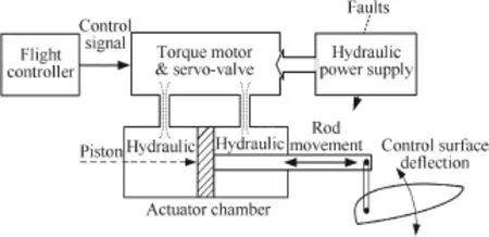
Fig.1 Diagram of a hydraulic-driven actuator.


Retracing the actuator redundancy defned in Ref.6,it is known that the aircraft has m-h redundant actuators.The worst case in which the confgured redundancy is capable of accommodating is that m-h actuators are complete failures. Before designing any passive FTC,the fault sets need to be determined within the capability of the confgured redundancy and the admissible solutions.
Let nodenote the number of the defned fault sets,the actuator faults/failures can be described by

where the scaling factor Li,i=0,1,...,nosatisfes:

If the fault sets are chosen as(∀i=0,1,...,no),the aircraft model can be subsequently written by

Each case in the considered fault sets is known a priori,which can be regarded as the corner of the polytope.In addition,the faulty system falls into the convex hullof these corners.Therefore,the aircraft system with the considered fault sets can be modeled by the polytopic uncertainties.19The system matrices are represented by

with the uncertain constant parameter vector θ=[θ0,θ1,...,θno]T∊Rno+1satisfying:

One convex of the polytope represents the normalcase,and each of the rest denotes the individualset of actuator outages. In summary,the aircraft model in the case of the faulty and normal conditions can be described by

Additionally,considering the linearized model under uncertainty14:

where[Δ A,ΔB ]=DF(t)[E1,E2],D,E1,and E2are known constant matrices,and F(t)∊Rd×wis the modeling or parameter uncertainty,which satisfes FT(t)F(t)≤I.Thus,the system with consideration of both uncertainty and actuator failures can be written by

where the matrices in Eq.(11)are

withθsatisfying Eq.(8)as well.
Remark 1.Since the specifed fault sets fall into the actuator outages,the matrices Ai,Bi,and Ci(i=0,1,...,no)are identical to the matrices A,B,and C of Eq.(1),in the case of one trimming condition.The uncertainty matricesΔAiand ΔBiare namely equivalent toΔA andΔB in Eq.(10).The individualprescribed set is identifed by the varying element Li, i=0,1,...,no.
3.Objective and formulation
3.1.Objective
The objective of this paper is to develop the passive FTCstrategies with regards to the model uncertainty-free and uncertainty cases in the presence of actuator failures.Within the considered actuator failures,the stability and tracking performance can be ensured.
3.2.Formulation
An integral part is introduced in the scheme of the designed passive FTC to eliminate the steady-state tracking error.7As shown in Fig.2,the designed passive FTC to counteract actuator failures is based on state feedback.
Given the considered fault sets,the corresponding augmented system without uncertainty is
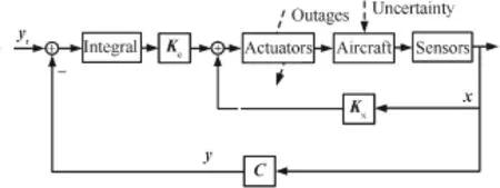
Fig.2 Scheme of the proposed passive FTC.

where e(t)=yr(t)-y(t),and yr(t)is the reference vector. When the augmented state vector is defned as xa(t)= [(∫e(t)d t)T,xT(t)]T,Eq.(13)can be simplifed by

where
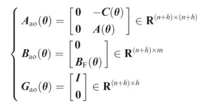
On basis of Eq.(12),the augmented system with consideration of uncertainty is

where

The performance output za(t)is defned by

For the sake of aircraft safety,it is required that safety bounds are not exceeded to prevent the handicapped aircraft entering an irreversible state(e.g.tail stall).On the other side, the amplitudes of actuator movements and system outputs highly rely on the commands.Therefore,it is of paramount importance to examine the relationships among the peak values of references,actuator outputs,and aircraft outputs.Based on this consideration,following peak-to-peak gain is proposed to be employed to represent such relationships in this paper:

where Tzayris the transfer function from yrto za,andγdenotes the upper bound of the peak-to-peak gain.As considering that actuator and system outputs are included in the chosen performance output,the physicalinterpretation behind Eq.(17)is to describe and link the peak values of actuator and system outputs in response to the maximum commands.Hence,the objective of designing passive FTCs against the considered fault cases turns to minimize the upper boundγand maintain the stability of the closed-loop system for allθ∊Θ.
4.Passive fault-tolerant fight controller design
Considering the designed passive FTC with respect to Eq.(9) in the following form which includes both proportional and integral actions:
where KPFTC=[Ke,Kx]∊Rm×(n+h).Thus,the closed-loop augmented system in the case of actuator outages is

Analogously,in the condition of model uncertainty,the closed-loop augmented system can be represented by

Subsequently,the regulated output is:

Theorem 1.(Uncertainty-free case).If there exist positive defnite matrices>0,i=0,1,...,no,matrices S and N,and scalarsλ>0,μ>0,γ>0 satisfying the following:


therefore,KPFTC=NS-1guarantees that system Eq.(19)is stabilized and the peak-to-peak norm of Tzayris smaller thanγ.Proof.In accordance with the suffcient condition of peak-to-peak gain in Ref.20and the multiple convexity concept proposed in Ref.21,the following inequalities hold true so that the peak-to-peak norm of the transfer function Tzayris less thanγ,


if yr∊L∞with‖yr‖∞≤1.
With the help of Projection Lemma in Ref.22,Eq.(26)is equivalent to Eq.(24), where V is a general matrix.

Defning S=V-Tand then pre-and post-multiplying Eq. (26)by diag(ST,I,ST)and diag(S,I,S),one can derive:
from system matrices;(2)parameter dependent Lyapunov method is adopted to set up different Lyapunov matrices in response to each prescribed set;and(3)the slack matrix S

where Y(θ)≜STP(θ)S.If N≜KPFTCS is defned,Eq.(27)is recast by the following inequality:
that does not have to be positive defnite replaces Lyapunov matrix.Thus the techniques ensure that the proposed algo-

If the condition Y(θ)=∑noi=0θiYiis satisfed,Eq.(28)can be represented by:

Therefore,for every i=0,1,...,no,Φi<0 guarantees that Eq.(29)holds true.
If Eq.(25)is pre-and post-multiplied by the following matrices diag(ST,I,ST) and diag(S,I,S) and defning N≜KPFTCS and Y(θ)≜STP(θ)S,thus:

Moreover,Eq.(30)can be written by:
rithm is less conservative compared with the classical method in Ref.20.
Remark3.At the design stage,the algorithm is to minimize the upper bound of peak-to-peak gainγsubject to Eqs.(22) and(23),where i=0,1,...,no.Using LMI Toolbox,23the passive FTC gain without consideration of model uncertainty is KPFTC=,where Noptand Soptare the optimalsolutions of matrices N and S,respectively.Theorem2.(Uncertainty case).If there exist positive defnite matrices>0,i=0,1,...,no,matrices S,N,and Q, and scalarsλ>0,μ>0,γ>0,ε>0 satisfying the following inequalities:

Therefore,it renders that Hi<0,i=0,1,...,nois the suffcient condition for Eq.(30)’s holding true.This completes the proof.
Remark2.Theorem 1 possesses three major advantages:(1) Projection Lemma22is used to decouple Lyapunov matrix


thus,KPFTC=NS-1guarantees that system Eq.(20)is stabilized and the peak-to-peak norm of Tzayris smaller thanγ.
Proof.In accordance with the suffcient condition of peak-topeak gain in Ref.20and the multiple convexity concept proposed in Ref.21,the following inequalities hold true so that the peak-to-peak norm of the uncertain system Eq.(20)is less thanγ,
where V is a general matrix.Similar to the derivation process of Eq.(22)and defning Q≜STP(θ),it is obtained that Eq.(32) is the suffcient condition for Eq.(34)holding true.In addition, the proof process of Eq.(33)is identical to that of Eq.(23)in Theorem 1.For the interest of space,it is omitted herein.This completes the proof.
Remark4.Theorem 2 offers an option of designing a passive FTC against actuator failures in the presence of model uncertainty.In the design process,the matrices D,E1,and E2,which are known to specify the degree of model uncertainty,are taken into account.As a result,the passive FTC generated


if yr∊L∞with‖yr‖∞≤1.According to the uncertainty representation,Eq.(34)equals to:
by Theorem 2 can not only accommodate the prescribed actuator failures,but also work in the case with modeling errors.
Remark5.By minimizing the upper bound of the peak-topeak gainγ,the maximum value of performance output

From Ref.14and FTF≤I,the following inequality holds true for anyε>0:

In consequence,the suffcient condition for Eq.(36)to be held is
(including the aircraft and actuator variables)can be estimated provided that the information of reference commands is known a priori.In this sense,the developed approach coincides with the requirements of safety-critical processes.In addition, this concept can also be extended to fight envelope protection in fault cases.

By virtue of Projection Lemma in Ref.22,Eq.(38)is equivalent to Eq.(39),

5.Numerical case studies
5.1.Developed simulation platform
The simulation platform that is developed by Diagnosis,Flight Control and Simulation Lab at Concordia University is illustrated in Fig.3.The platform is basically made up by two units.The controller to be validated,actuator models,sensor models,and aircraft models are integrated in Unit 1.For the convenience of simulation,the functionalities of data storage and failure injection are designed as well.The data from Unit 1 are transmitted to Unit 2 by User Datagram Protocol(UDP) networks.Unit 2 is designed to demonstrate the fight animation of the selected aircraft using FlightGear software.
5.2.Selected aircraft model
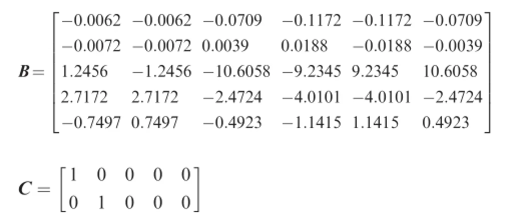
In the selected ADMIRE model,the state vector is defned as x(t)=[α,β,p,q,r]T,the control input vector is u(t)=[δRC,δLC,δROE,δRIE,δLIE,δLOE]T,and the system output vector is y(t)=[α,β]T.α,β,p,q,and r are the AOA,sideslip angle, roll rate,pitch rate,and yaw rate,respectively.The control inputsδRC,δLC,δROE,δRIE,δLIE,andδLOEspecify the defections of right canard(RC),left canard(LC),right outer elevon (ROE),right inner elevon(RIE),left inner elevon(LIE),and left outer elevon(LOE),respectively.The actuator dynamics is modeled by 1/(0.05s+1).The operating range of each actuator is[-25?,25?].The trimming conditions are detailed in Table 1,under which the system matrices are:

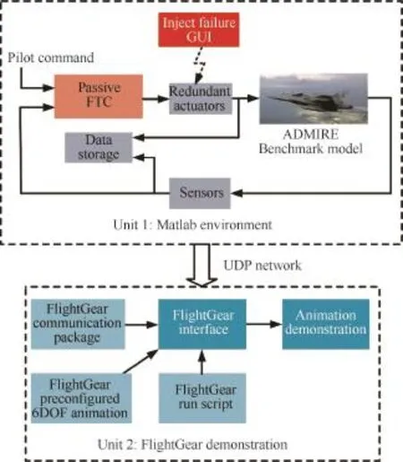
Fig.3 Diagram of the developed simulation platform.
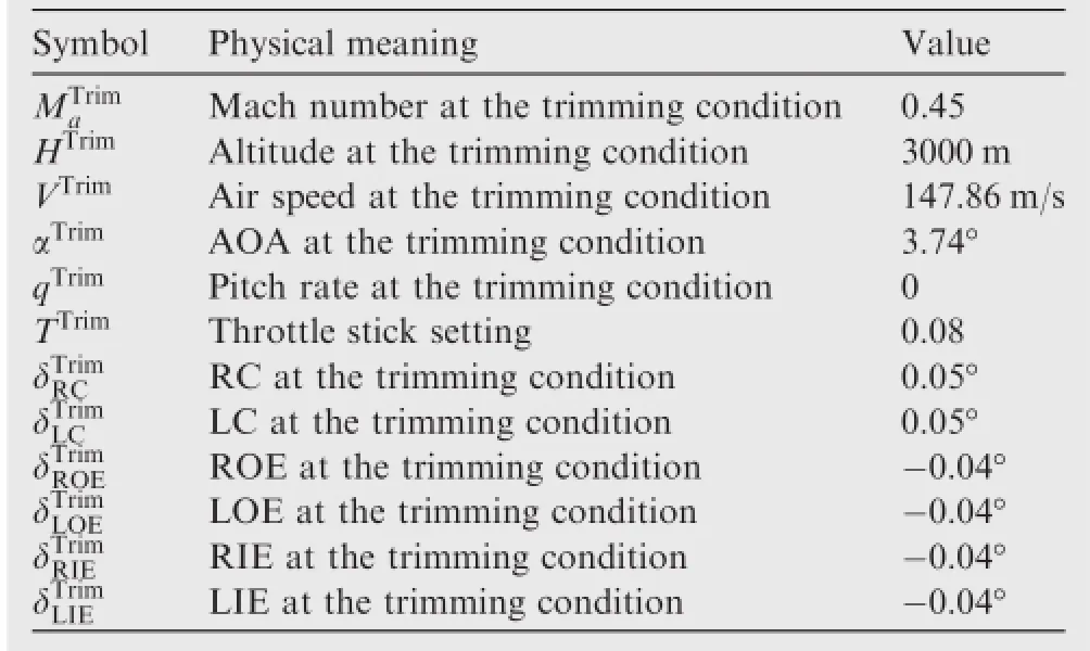
Table1 Trimming condition of the ADMIRE model.
5.3.Simulation scenarios
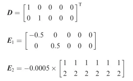
Two simulation scenarios are set up,which are(1)ADMIRE model without uncertainty;and(2)ADMIRE model with model uncertainty.It should be mentioned that in scenario 2,the model uncertainty matrices are:
The reference signals of AOA and sideslip angle with amplitudes of 5?and 1?are initiated at 1 s.The four elevons are assumed to become complete failures at 10 s.In the numerical simulation studies,a nominal controller,20a LQ/H∞-based passive FTC,7and the proposed passive FTC are implemented and compared,respectively.Interested readers can visit web www.youtube.com/user/NAVConcordia or http://i.youku. com/NAVConcordia to watch the video clips of ADMIRE animation under those three control strategies.The detailed comparison and evaluation are provided as follows.
5.4.Results of Scenario 1 and evaluation
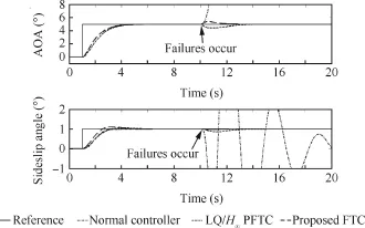
Fig.4 Aircraft output responses in Scenario 1.
As can be seen from Fig.4,the nominal controller,LQ/H∞-based passive FTC(PFTC),and proposed passive FTC can maintain the tracking performance when all actuators are working normally.It is indicated by Table 2 in the normalcondition,the AOA(2.64 s,0%)and sideslip angle(1.99 s,0%) track the commands with superior performance under the nominal controller as compared with those in the LQ/H∞-based passive FTC and proposed passive FTC.It is true since the nominalcontroller is only concentrated on the best performance in the normal condition.From Fig.5,when all actuators are healthy,the LQ/H∞-based passive FTC drives RC and LC to defect more angles than those under the nominal controller and the proposed passive FTC.When the LQ/H∞-based passive FTC is commissioned,it is easy to reach the physicallimits of RC and LC even though the aircraft is fying ordinarily.
When all elevons are outages at 10 s,the safety cannot be ensured by the nominal controller any more as the AOA and sideslip angle become oscillatory as the dash-dot lines shown in Fig.4.In this situation,the aircraft becomes unstable and unrecoverable as the physicalbounds are broken.By contrast, the LQ/H∞-based passive FTC and the designed passive FTC are capable of keeping the faulty aircraft stabilized and returning the aircraft outputs to the intended angles.Fig.4 and Table 2 also indicate that the returning time and overshoot of AOA(2.35 s,11.8%)and sideslip angle(2.7 s,14.4%) achieved by the LQ/H∞-based strategy are interior to those by the proposed FTC(AOA:1.4 s,10%;sideslip angle: 0.75 s,4%).Fig.5 exhibits that after elevon outages occur, RC and LC are saturated under supervision of the nominal controller.However,when the proposed passive FTC is commissioned,the amplitudes of the healthy actuators are considerably less than those of the normal controller.Therefore,the results of scenario 1 illustrate that the designed passive FTC can not only maintain the safety of the airplane when the prescribed failures occur,but also obtain an acceptable level of performance.
5.5.Results of scenario 2 and assessment
The simulation results of scenario 2 are illustrated by Figs.6 and 7 and Table 3.As shown in Fig.6,before elevon outages occur,AOA and sideslip angle can track the reference signals under the selected three controllers.However,the settling time and overshoot of AOA and sideslip angle achieved by the nominalcontroller and LQ/H∞-based passive FTC are considerably degraded as comparison of those without model uncertainty.The degree of performance degradation in the developed FTC is remarkably less than those by the other two controllers.The details are:(1)the performance of AOA returning time,sideslip angle returning time,sideslip angle overshoot in the case of nominal controller is decreased by 27.27%,53.27%,and 0→2.5%,respectively;(2)when the LQ/H∞-based passive FTC is used,the degraded degree of the above performance is 28.42%,40.53%,and 185.71%, respectively;and(3)under the proposed FTC,the performance degradation of AOA returning time,sideslip angle returning time,sideslip angle overshoot is 24.13%,0.96%,and 53.85%,respectively.
After elevon outages,the nominal control strategy cannot guarantee the safety of the faulty aircraft.Although the LQ/ H∞-based passive FTC can counteract elevon failures as shown in Fig.6,the system performance is greatly deteriorated according to Tables 2 and 3.On the other hand,the developed passive FTC with consideration of model uncertainty is capable of obtaining better performance rather than those under the other two controllers.Moreover,the performance achieved by the proposed FTC is slightly degraded in comparison of the model uncertainty-free case.Based on Fig.7,the redundant actuators RC and LC defect more than the normal case(before 10 s)so as to accommodate the elevon failures and maintain the safety of the faulty system.It is alsodemonstrated by Fig.7 and Table 3 that the peak values of actuator defections are controlled within the allowable operating ranges by the proposed passive FTC.
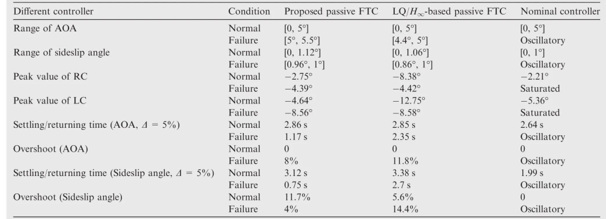
Table2 Performance of the three controllers in Scenario 1.
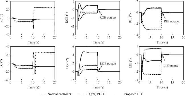
Fig.5 Actuator defections in Scenario 1.
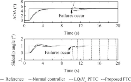
Fig.6 Aircraft output responses in Scenario 2.
Thus,it is known that model uncertainty is detrimental to performance both in normaland faulty cases.The comparison also illustrates that the developed passive FTC is a viable option of compensating for the adverse effects caused by model uncertainty and actuator failures.
5.6.Results of nonlinear simulation
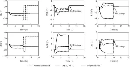
Fig.7 Actuator defections in Scenario 2.
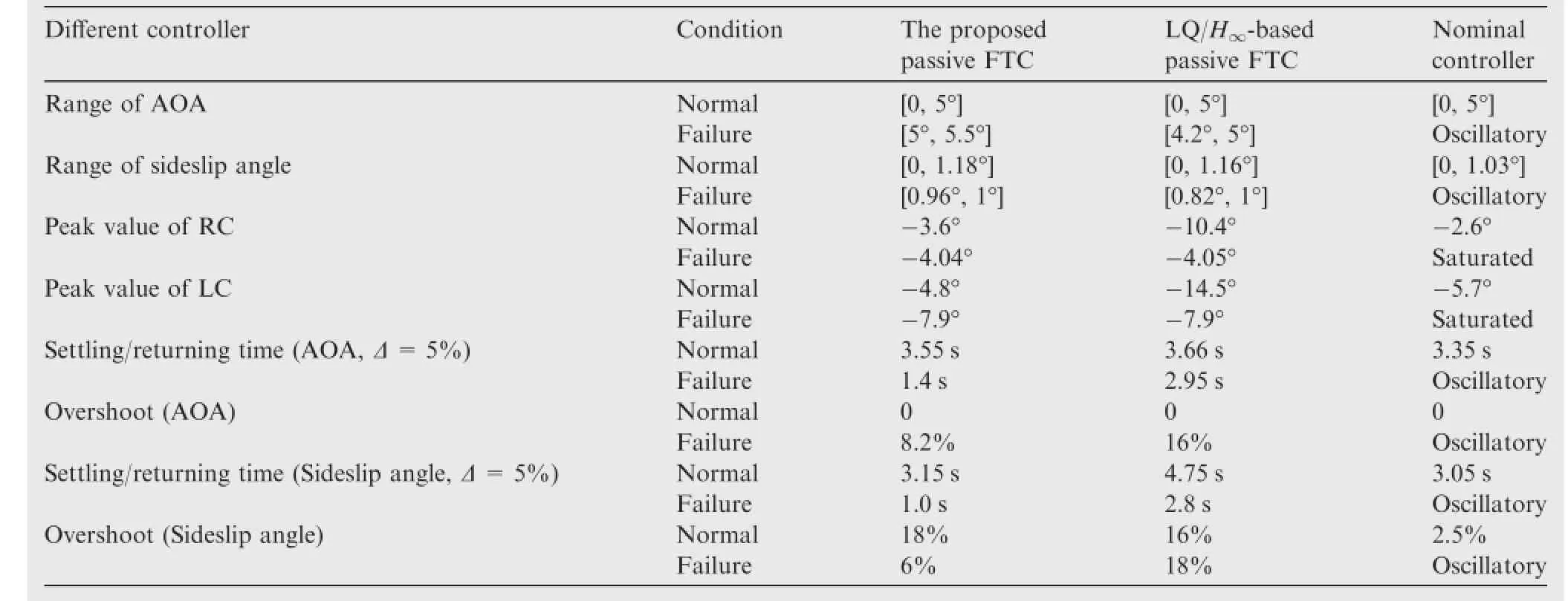
Table3 Performance of the three controllers in Scenario 2.
Scenarios 1 and 2 are further investigated in the case with nonlinear dynamics of the selected ADMIRE for the purpose of further verifying the proposed passive FTCs.It is shown in Fig.8 that without model uncertainty,the AOA and sideslip angle are controlled to return the intended angles after all elevon complete failures(at 10 s).Based on Fig.9,the designed passive FTC can still maintain the safety of the aircraft in the presence of elevon outages and model uncertainty.Fig.9 exemplifes that the developed controller with explicit consideration of modeluncertainty can obtain gracefully degraded performance as compared to the uncertainty-free case illustrated in Fig.8.
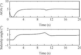
Fig.8 Aircraft outputs in nonlinear simulation without model uncertainty.
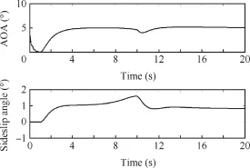
Fig.9 Aircraft outputs in nonlinear simulation of developed controller with explicit consideration of model uncertainty.
6.Conclusion remarks
The prescribed actuator failures are developed in terms of polytopic uncertainty.Peak-to-peak norm of the closed-loop system is adopted to describe the relationships among the maximal values of actuator outputs,reference signals,and system outputs.Based on a clear understanding of the safety requirements,the concept of peak-to-peak gain is incorporated in the design procedure of passive FTC,in which the parameter dependent Lyapunov and slack variable methods are applied for reducing conservatism.From a practical perspective,the passive FTC strategies corresponding to model uncertaintyfree and uncertainty cases are investigated.Both linear and nonlinear simulation studies subject to the ADMIRE aircraft model with elevon outages are conducted.It is demonstrated conclusively that the developed approach is effective in the presence of both actuator failures and model uncertainty.
Acknowledgement
The authors would like to acknowledge the fnancial support from the Natural Sciences and Engineering Research Council of Canada(NSERC)through Discovery Grant and Engage Grant for the work reported in this paper.
1.Zhang YM,Jiang J.Bibliographical review on reconfgurable fault-tolerantcontrolsystems.Ann Rev Control2008;32(2):229–52.
2.Blanke M,Kinnaert M,Lunze J,Staroswiecki M.Diagnosis and fault-tolerant control.2nd ed.Berlin Heidelberg:Springer-Verlag; 2006.
3.Jiang J,Yu X.Fault-tolerantcontrolsystems:a comparative study between active and passive approaches.Ann Rev Control 2012; 36(1):60–72.
4.Veillette RJ,Medanic JV,Perkins WR.Design of reliable control systems.IEEE Trans Autom Control 1992;37(3):290–304.
5.Veillette RJ.Reliable linear-quadratic state-feedback control. Automatica 1995;31(1):137–43.
6.Zhao Q,Jiang J.Reliable state feedback control systems design against actuator failures.Automatica 1998;34(10):1267–72.
7.Liao F,Wang JL,Yang GH.Reliable robust fight tracking control:an LMI approach.IEEE Trans Control Syst Technol 2002;10(1):76–89.
8.Zhang Q,Ye S,Li Y,Wang X.An enhanced LMI approach for mized H2/H∞fight tracking control.Chin J Aeronaut 2011;24(3): 324–8.
9.Liang YW,Liaw DC,Lee TC.Reliable control of nonlinear systems.IEEE Trans Autom Control 2000;45(4):706–10.
10.Yang GH,Lam J,Wang JL.Reliable H∞control for affne nonlinear systems.IEEE Trans Autom Control1998;43(8):1112–7.
11.Liang YW,Xu SD.Reliable control of nonlinear systems via variable structure scheme.IEEE Trans Autom Control2006;51(10): 1721–6.
12.Benosman M,Lum KY.Application of passivity and cascade structure to robust control against loss of actuator effectiveness. Int J Robust Nonlinear Control 2010;20(6):673–93.
13.Wang RR,Wang JM.Passive actautor fault-tolerant controlfor a class ofoveractuated nonlinear systems and applications to electric vehicles.IEEE Trans Veh Technol 2013;62(3):972–85.
14.Zhou K.Khargonekar PP.Robust stabilization of linear systems with norm-bounded time-varying uncertainty.Syst Control Lett 1988;10(1):17–20.
15.Kang R,Jiao Z,Wang S,Chen L.Design and simulation of electro-hydrostatic actuator with a built-in power regulator.Chin J Aeronaut 2009;22(6):700–6.
16.Yu X,Jiang J.Hybrid fault-tolerant fight control system design against partialactuator failures.IEEE Trans Control Syst Technol 2012;20(4):871–86.
17.Niksefat N,Sepehri N.A QFT fault-tolerant control for electrohydraulic positioning systems.IEEE Trans Control Syst Technol 2002;10(4):626–32.
18.Zhang YM,Jiang J.Active fault-tolerant control system against partial actuator failures.IEE Proc Control Theory Appl 2002; 149(1):95–104.
19.Shaked U.Improved LMI representations for the analysis and the design ofcontinuous-time systems with polytopic type uncertainty. IEEE Trans Autom Control 2001;46(4):652–6.
20.Scherer C,Weiland S.Linear matrix inequalities in control.Delft:Delft University;2004.
21.Gahinet P,Apkarian P,Chilali M.Affne parameter-dependent Lyapunov functions and parameter uncertainty.IEEE Trans Autom Control 1996;41(3):436–42.
22.Gahinet P,Apkarian P.A linear matrix inequality approach to H∞control.Int J Robust Nonlinear Control1994;4(4):421–48.
23.Boyd SP,Ghaoui E,Feron L,Balakrishnan V.Linear matrix inequalities in system and controltheory.Philadelphia,PA:SIAM; 1994.
YuXiangreceived the B.S.,M.S.,and Ph.D.degrees from Northwestern PolytechnicalUniversity,in 2003,2004,and 2008,respectively. He is currently a Research Associate in the Department of Mechanical &Industrial Engineering at Concordia University,Montreal,Canada. His research interests include fault-tolerant control systems,fight control systems,and networked-based control systems.
ZhangYouminreceived the B.S.,M.S.,and Ph.D.degrees from Northwestern Polytechnical University,in 1983,1986,and 1995, respectively.Dr.Zhang is currently a full Professor in the Department of Mechanical&Industrial Engineering at Concordia University, Montreal,Canada.His main research interests are in the areas of monitoring,fault diagnosis and fault-tolerant controlof safety-critical systems;avionics,guidance,navigation,and cooperative control of manned and unmanned aerial/space/ground/surface vehicles.Dr. Zhang has published 4 books,10 book chapters,and more than 330 refereed journal and conference papers.He serves as a member of the IFAC Technical Committee on SAFEPROCESS,a member of the AIAA Infotech@Aerospace Program Committee on Unmanned Systems etc.He is the Editor-in-Chief of Journal of Instrumentation, Automation and Systems,and an Editorial Board Member of several journals,and the Program Chair of ICUAS’14,General Chair of ICIUS’14 and ICUAS’15.
Received 10 July 2014;revised 16 September 2014;accepted 31 October 2014
Available online 24 December 2014
*Corresponding author.Tel.:+1 514 848 2424x5225.
E-mail address:youmin.zhang@concordia.ca(Y.Zhang).
Peer review under responsibility of Editorial Committee of CJA.

