
Design of high-speed and low-power finite-word-length PID controllers
2014-12-07 05:13:53OUDJIDACHAILLETLIACHABERRANDJIAHAMERLAIN
Control Theory and Technology 2014年1期
A.K.OUDJIDA,N.CHAILLET,A.LIACHA,M.L.BERRANDJIA,M.HAMERLAIN
1.Centre de De´veloppement des Technologies Avance´es,Algiers,Algeria;
2.FEMTO-ST Institute,Besanc¸on,France
Design of high-speed and low-power finite-word-length PID controllers
A.K.OUDJIDA1†,N.CHAILLET2,A.LIACHA1,M.L.BERRANDJIA1,M.HAMERLAIN1
1.Centre de De´veloppement des Technologies Avance´es,Algiers,Algeria;
2.FEMTO-ST Institute,Besanc¸on,France
ASIC or FPGA implementation of a finite word-length PID controller requires a double expertise:in control system and hardware design. In this paper, we only focus on the hardware side of the problem. We show how to design configurable fixed-point PIDs to satisfy applications requiring minimal power consumption,or high control-rate,or both together.As multiply operation is the engine of PID,we experienced three algorithms:Booth,modified Booth,and a new recursive multi-bit multiplication algorithm.This later enables the construction of finely grained PID structures with bit-level and unit-time precision.Such a feature permits to tailor the PID to the desired performance and power budget.All PIDs are implemented at register-transfer-level(RTL)level as technology-independent reusable IP-cores.They are reconfigurable according to two compile-time constants:set-point word-length and latency. To make PID design easily reproducible, all necessary implementation details are provided and discussed.
Design-reuse;Embedded finite-word-length(FWL)controllers;Intellectual property(IP);Linear time invariant(LTI)systems;Low-power and speed optimization;PID
1 Introduction
The PID is by far the most commonly used feedback controller due to its simple structure and robust performance[1].An important feature of this controller is that it does not require a precise analytical model of the system that is being controlled,which makes it very attractive for a large class of dynamic systems.While PID is well adapted for linear-time-invariant(LTI)systems[2],it stands powerless for non-LTI ones.Nevertheless some solutions exist,such as partitioning the non-LTI control algorithm into a linear portion and a nonlinear portion[3–5].The linear portion represents the major control loop and is computed using an integrated PID,while the nonlinear portion that acts as dynamic compensation to the linear one is performed in software using a general-purpose-microprocessor or a DSP.
In embedded control applications,such as in small-scale mobile robot,the control-loop-cycle is very tight and the power budget is very limited.A low sample rate leads to poor and degraded control-performance.Moreover,high power consumption shortens the battery lifetime.To cope with these two severe and antagonistic constraints,the need for both a high-speed and low-power PID structure is of utmost importance.
Today,design-reuse[6]is a well-established design standard that allows grasping with rapid technology changes and increasing design complexity.It consists in the use of predesigned technology-independent, generic and reconfigurable IP-cores[7],most generally implemented at register-transfer-level(RTL).
However,at RTL abstraction level,no significant optimization results can be achieved if not undertaken at architectural and especially at algorithmic level. To achieve such a goal,a deep insight into PID arithmetic is necessary.At this stage,a choice of a numeric representation format is a crucial issue.Compared to floating-point, fixed-point format is the best candidate for optimized designs as it is much simpler to implement,faster,power efficient and requires far much less hardware resources.However,the limited dynamic range can be source of control instability.This problem,referred to as finite word-length(FWL)effect is an active research area that aims to shorten the floating-to-fixed point conversion time while preserving control performances[8,9].
The digital implementation of PID controllers went through several stages of evolution,initially dominated by the use of commercial-of-the-shelf(COTS)components and DSP.However,over the past few years,FPGAs have brought a key advantage to digital control:the inherent parallelism of FPGA architecture allows many independent control loops to run at different deterministic rates without relying on shared resources that might slow down their responsiveness as in the case of COTS and DSP[10,11].
A survey of recent PID related works can be classified into three categories.The biggest one includes works that are straightforward FPGA implementations targeting specific applications:DC-DC converter[12],temperature control[13],motor multi-axis control[14],liquid level control[15],and Xilinx versus Altera FPGA implementation for result comparison[16].The second category proposes methodologies that analyze the FWL effect on PID controller in order to reduce the number of hardware resources[17,18].Moreover,finally the third category,paradoxically the smallest one despite the large popularity of PID, comprises architecture optimization works.In[19],low-power serial and parallel multiple-channel PID architectures are proposed for small mobile robots.In this work,the optimization was carried out at macro-level considering several PIDs,rather than at micro-level(optimization of the PID itself).Nevertheless, the whole architecture will deliver much more interesting results if combined with an optimized PID.The second work[20]proposes serial,parallel,and mixed PID architectures incorporating different number(1–3)of multiplication cores.High power consumption,even with the serial architecture,and complex control-part are the two major shortcomings of this proposal.Finally,in[21],an attractive optimized PID structure based on distributed arithmetic(DA)is presented. Although this latter exhibits interesting results in terms of resource utilization and power consumption,it suffers from three serious drawbacks:high latency(n+1 clock-cycles fornbit set-point word length),FPGA technology-dependent as it is essentially based upon FPGA look-up-tables(LUTs),and inability to handle time-varying PID parameters since they are precomputed and stored into LUTs.Nevertheless,it is considered as a reference design against which the obtained results are confronted into the same conditions.
The objective of this paper is to design optimized FWL-PID structures that overcome all the abovementioned shortcomings,and which are especially dedicated to embedded control applications.The PID cores are described at RTL level. They are highly reconfigurable and technology-independent,offering the possibility to be mapped both on FPGA and ASIC.
To reach such a goal,a special focus was put on the optimization of the inner arithmetic of PID.For that,we considered two discrete forms of PID algorithm:the commercial form[22],called also the standard or ISA form,and the incremental form.These two forms went through three successive types of FPGA implementations,using:Booth multiplication algorithm(BMA)[23],modified Booth multiplication algorithm(MBMA)[24],and a new developed version called recursive multibit recoding multiplication algorithm(RMRMA)[25].Results show gradual improvements with clear superiority over those provided in [21]. PID control-rate and energy consumption savings are respectively as follows:32%and 25%with BMA,177%and 23%with MBMA,431%and 20%with RMRMA.
Our previous paper[26]introduced a limited designspace of PID.In this paper,we extended the designspace to accommodate different application cases and provided all necessary implementation details to make the design easily reproducible.
The paper is organized as follows.In this section we outlined the main requirement specifications for embedded PID controller.Section 2 introduces the two mostly-used discrete versions of PID algorithm.Sections 3,4 and 5 deal with BMA,MBMA and RMRMA implementations,respectively.A discussion around the obtained results is given in Section 6.Section7describes the verification method,while Section 8 shows how the FWL-effect is tackled.Moreover,finally some concluding remarks in Section 9.
2 The two mostly-used discrete versions of PID
A typical closed-loop system using a PID controller is shown in Fig.1,whereuc(k),y(k),andu(k)are the discrete signal quantities at thekth sampling instant of the reference set-point,the process-feedback measured output,and the PID controller output,respectively.
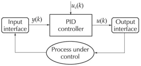
Fig.1 Typical closed-loop control system using a PID.
In digital control,commercial and incremental forms are the two mostly-used discrete PID versions[1,22].They are denoted by recurrent equations(1)and(2),respectively,and their corresponding coefficients are grouped in Table 1.Equations(1)and(2)are fully detailed in the Appendix.
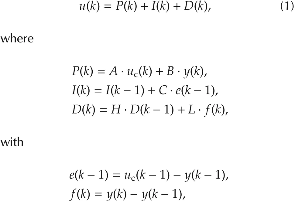
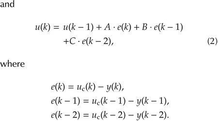
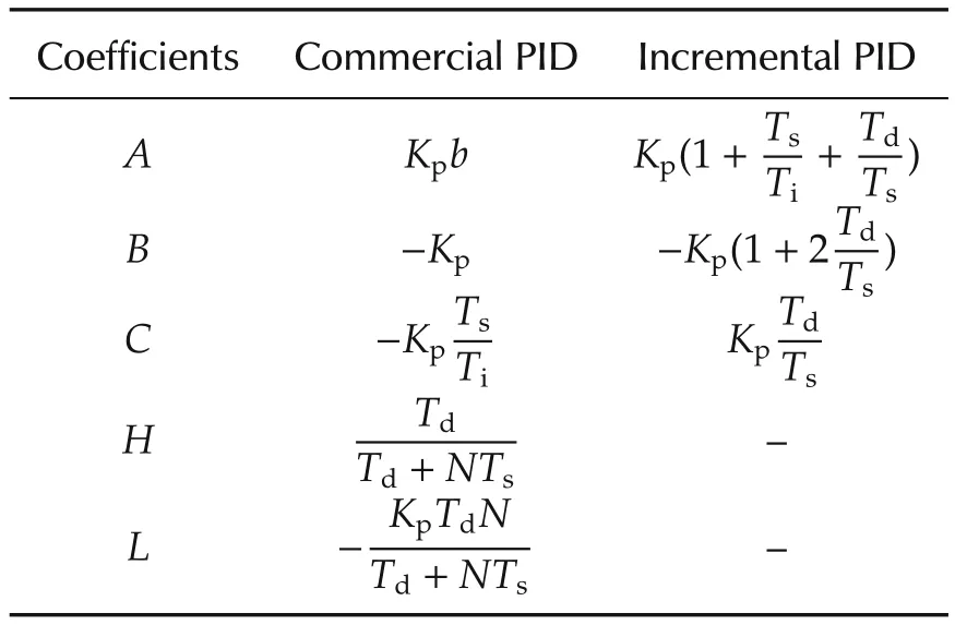
Table 1 Coefficients of discret recurrent equations.
Kpis the proportional gain;TiandTdare the integral and derivative times,respectively;Nis the maximum derivative gain;bis the fraction of set-point in proportional term;andTsis the sampling period.
To satisfy different application cases,two IP versions are developed for each equation:with constant coefficients and with varying coefficients(Fig.2).This latter requires a host side interface (HSI) to handle the runtime change of the coefficients.
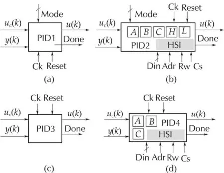
Fig.2 Various PID IP-cores.(a)Commercial PID with constant coefficients;(b)commercial PID with time varying coefficients;(c)incremental PID with constant coefficients;and(d)incremental PID with time varying coefficients.
The commercial version allows the three standard PID functioning modes(P,PI,PID)according to Mode input value.At the end ofu(k)computation,the Done output signal toggles during one clock cycle,and the PID enters into sleep mode(whole internal activity stopped except for clocking and HSI) for maximum energy conservation.
3 MBA-based PID
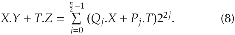
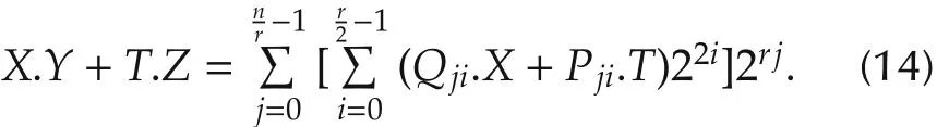
A straightforward parallel implementation of PID requires an amount of 7 adders/substractors and 5 multiplication cores for equation (1),and 4 adders/substractors and 3 multiplication cores for equation(2).In digital hardware,the total gate count scales linearly with word length for an adder core,while it scales quadratically for a multiplier core.Thus,any effort for a low-power optimization of PID must be focused on the implementation of the multiply-and-accumulate(MAC)function(X·Y)[27].In this work,the optimization effort is rather concentrated on the double MAC function(X·Y+T·Z)called DMAC,considered as the main building block of our PID structures.Equations(1)and(2)are partitioned accordingly.
For FWL-PID,two’s complement fixed-point representation is used,which is habitually expressed inQnotation asQni.nf.The values are coded innibits before the point(integer word length including 1 sign bit),andnfbits after the point(fractional word length).The total word length isn=ni+nf.
Booth multiplication algorithm[23]belongs to the class of recoding algorithm,i.e.,algorithms that recode one of the two operands to cope with signed two’s complement multiplication.LetYbe the multiplier:
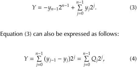
wherey−1=0 andQj∈ {−1,0,1}.
Consequently,the multiplierYis divided intonslices,each of 2 bits.Each pair of two contiguous slices has one bit in common.Thus,the DMAC becomes
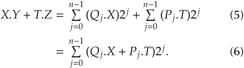
According to (5), Booth algorithm consists in recoding the multiplierYinto a set of ternary numbers{−1,0,1}in order to generatensimple partial products which are summed subsequently.Table 2 summarizes the 4 possibilities that may occur.The−Xcan be easily formed by adding 1 to the complement ofX.A direct translation of DMAC equation(5)into architecture(Fig.3)requires one extra adder and two registers in comparison with the optimized version(Fig.4)based on(6),called ODMAC.Additionally,one clock cycle latency is also needed in Fig.3.The control-part responsible of producing the successive couples(yj−1,yj)is insignificant:just one multiplexer driven by a counter.

Table 2 Booth algorithm.
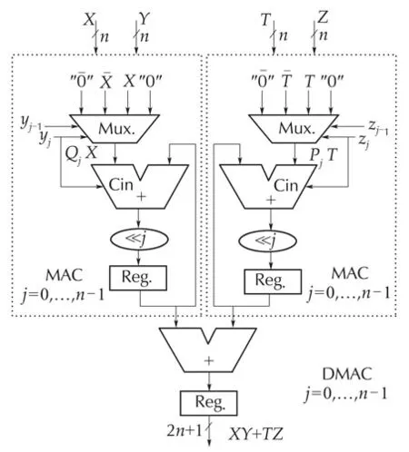
Fig.3 Straightforward DMAC implementation.
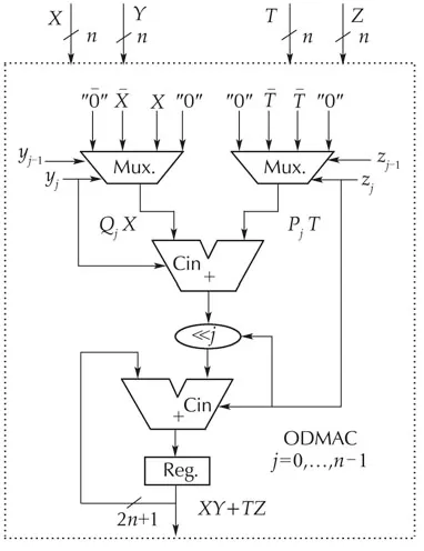
Fig.4 Optimized DMAC implementation.
Based upon ODMAC as the main building block,PID architectures are constructed for both incremental(Fig.5)and commercial(Fig.6)forms,and their implementation results(Table3)are respectively compared to those of[21].Comparison was made into identical conditions using the same FPGA device(Spartan XC2S50E-7FT256),although relatively old,as well as the same synthesis-tool version(Xilinx ISE 9.1i).In[21],only a 16-bit word-length commercial version with constant coefficients(without HSI)is implemented.PID1 and PID3 exhibits interesting results:44%,25%,and 32%savings and 62%,35%,and 38%savings in terms of gate count,power,and speed,respectively.PID3 exhibits higher savings but at the expense of control-quality.Latency is rather the same(17),which isn+1 clock cycles for all designs(PIDX).
Optimizing latency without sacrificing the three other issues is the main objective of the next two sections.

Fig.5 Incremental PID architecture.

Fig.6 Commercial PID architecture.
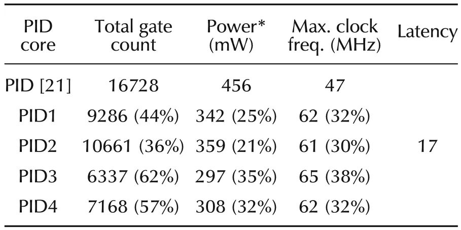
Table 3 Implementation result comparision of MBA-based PID.
4MBMA-based PID
Equation(3)can also be rewritten as follows[24]:

wherey−1=0 andQj∈ {−2,−1,0,1,2}.
In this case,the multiplierYis divided inton/2 slices,each of 3 bits,with one bit overlapping between adjacent slices.The proof of equation(7)is given in[28].Thus,the DMAC equation becomes:
Likewise,n/2 simple partial products are generated(Table 4).Since ODMAC is a reconfigurable RTL block,it is parameterized to suit equation(8).The new adapted ODMAC architecture is depicted in Fig.7.The only dif-ference is that Mux(8:1)are used instead of Mux(4:1),and(≪ 2.j)hardwired shifter instead(≪ 1.j).Compared to BMA-based PID(Table 5),MBMA-based one(PID1)shows much more interesting results,since latency is divided by 2 while maintaining stable power consumption and speed. Control rate is drastically improved as its equal to maximum clock frequency divided by latency.As the discrete commercial form(equation(1))can accommodate the three functioning modes,implementation of PID2 produced the following power consumption values at 47MHz:268mW,313mW,and 366mW for P,PI,and PID functioning modes,respectively.
With regard of these improvements,one is encouraged to pursue farther[24]in reducing latency by considering larger slices,such as
wherey−1=0 andQj∈ {−4,...,0,...,4}.
However,in this case,some hard partial products are required such as 3Xand−3Xwhich are not easy to generate.How to circumvent this obstacle is the purpose of the next section.

Table 4 Modified booth algorithm.
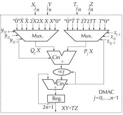
Fig.7 Optimized DMAC architecture for r=2.
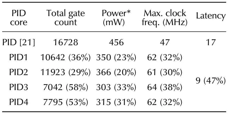
Table 5 Implementation result comparison of MBMA-based PID.
5RMRMA-based PID
Multiplication is a fundamental operation in digital design.Its speed and power requirements are two critical factors limiting the whole system performances(PID in our case).Since the publication of Booth’s algorithm in 1951,a huge number of improvement attempts were proposed,especially after the publication of a generalized version of MBA algorithm accompanied with its proof[29].Most of the proposals aimed to reduce the number of partial products either by employing digital optimization techniques[30–32]or by using larger slices(higher radices)[33].However,experience showed[34]that beyond 4-bit slices(radix 8),the complexity to generate hard partial products cannot be managed in a realistic way.In[34],three metrics are provided for comparing the tradoffs when employing higher radix Booth recodings:partial product compression factor(gain),the number of hard multiples that must be precomputed(computation complexity),and partial product generation fanin(routing complexity).
To circumvent the problem of hard partial products in higher radices,the idea proposed in[35]is to apply a recursive Booth recoding on ther-bit slice.While the idea is interesting,it relies upon a complicated mathematical formulation,leading to a complex control circuitry and especially to an exaggerated latency(2n/r).
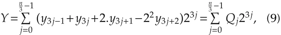
According to the multibit recoding algorithm presented in[29],an-bit two’s complement operandYcan be written as
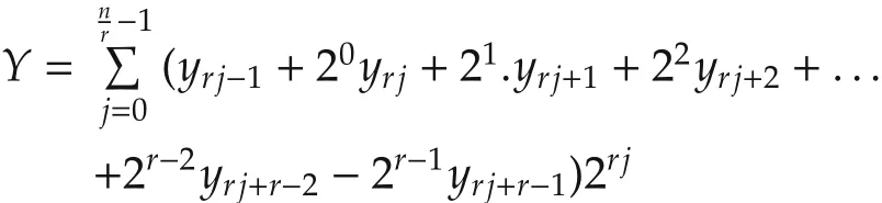

wherey−1=0,r∈N∗andQj∈ {−2r−1,...,0,...,2r−1}.
In this general case,the multiplierYis divided inton/rslices,each ofr+1 bits.Each pair of two contiguous slices has one overlapping bit.To bypass the problem of hard partial products,MBMA(equation(7))is applied to theQjterms.Thus,equation(10)takes the new simpler recursive form:
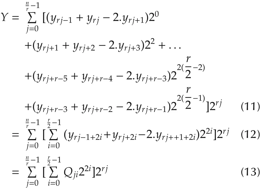
withQji∈ {−2,−1,0,1,2}.
There is no need to prove equation(11)since it is a combination of equations(10)and(7)which were already proven in[29]and[28],respectively.The partitioning of operandYaccording to equation(13)is illustrated by Fig.8.

Fig.8 Partitioning of a 16-bit Y operand with r=8.
To avoid dealing with special cases,nandrmust be chosen as even numbers,withras a divider ofn.Thus,the DMAC equation becomes
Depending onrvalue ranging from 2 ton,PIDs with various levels of parallelism and latencies(n/r+1)can be automatically generated with slight control complexity.The special cases ofr=nandr=2 correspond to fully-parallel and fully-sequential PID,respectively.In between(r=4,n/2),partially-parallel PIDs are obtained.The outstanding advantage of this algorithm(equation(13))is that hard partial products are generated using simple ones(2X,X)only.For a simplified hardware and lower power consumption,the step-bystep sign-propagate technique is employed[36].
Obviously,equation(13)does not reduce the number of partial products,but allows a modulable space-time partitioning of the multibit recoding algorithm(equation(10)),wheren/rsets comprising eachr/2 partial products can be generated and summed either simultaneously or iteratively.Whilst the parallel implementation of equation(13)allows an important reduction of the critical path(using a carry-save adder CSA),it requires too much space.Therefore,only the serial implementation is retained.In this case,latency drops from(n/2+1)to(n/r+1),whereas the overhead on the total critical path,which goes through log2(r/2)adder levels and which is equal toDin the case of MBMA,is slightly increasedD+log2(r/2).Note that we are using a logarithmic summation tree and not a linear one(CSA like).
An illustrative serial example withr=4 is described as follows:
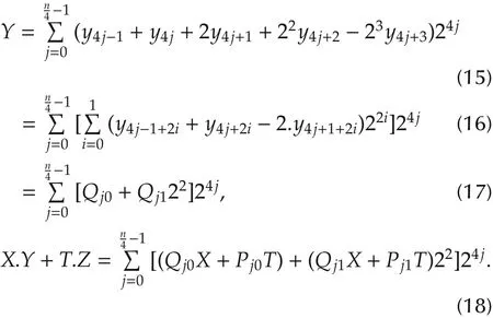
The mapping of equation(18)into a serial architecture is shown in Fig.9.Such a case(r=4)would have required the computation of hard partial products(7X,5X,3X)if the simple form of equation(15)was used.Notice that MBMA is a special case of RMRMA forr=2.Forr=1,equation(10)corresponds to BMA(equation(4)).

Fig.9 Optimized DMAC architecture for r=4.
Table 6 comprises the implementation results of PIDs withn=16 andr=4,8,16.For instance,PID1 withr=4 not only achieves high improvement in latency(71%),but also maintains positive savings in power(14%)and speed(13%).These important achievements are partially due to logic-trimming performed by the synthesis tool on the constant coefficients.Such an operation is impossible in the case of PID[21]since the coefficients are stored into LUTs.

Table 6 Implementation result comparison of RMRMA-based PID.
At this stage,a key question arises:among this panoply of PIDs,which one fits the best one’s application case?The answer to this question is given in the next section.
6 Discussion
In embedded control,satisfactory control-rate(without performance degradation)at minimum power consumption is the main requirement.To select the most adequate PID for a given application,it is necessary to investigate how speed,power and hardware resources scales versusrfactor for a fixed word lengthn.Referring to equation(14)and aided by Fig.9,the ODMAC architecture scales as a binary tree with one stage ofrmux(8:1)followed by log2(r)+1 stages of adders with a total ofradders too.Thus,the total delay cumulated by the critical path which goes through log2(r)+2 stages increases with O(log(r))complexity,whilst latency(n/r+1)decreases linearly O(r),which makes the maximum control-rate increases asrincreases.This is confirmed by implementation results shown in Tables 7 and 8 corresponding to PID1 and PID2,respectively.The sole exception to this general rule is PIDX_n/2 which always yields to the highest control-rate compared to PIDX_ndespite the numerous tests with variousnvalues.This is justified since they exhibit very close latencies(3 and 2,respectively)and one stage difference in the critical path(n−1 andn,respectively),but an important multiplexer fanin difference(n/4 andn/2,respectively).
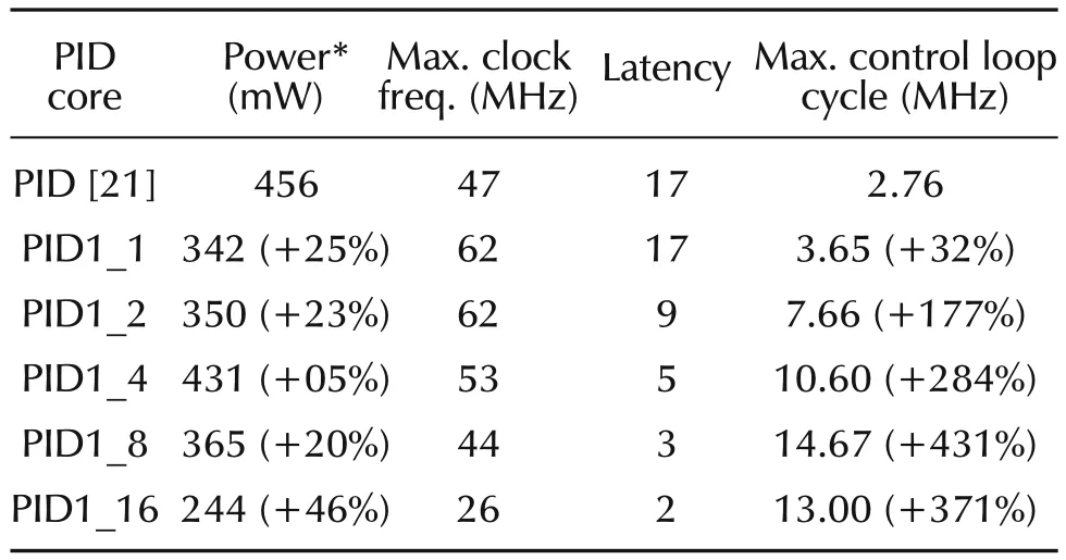
Table 7 Maximum power-consumption and control-loop-cycle of PID1.
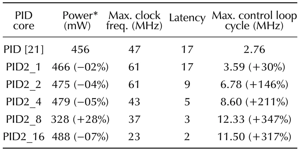
Table 8 Maximum power-consumption and control-loop-cycle of PID2.
In terms of resource occupation,the total complexity grows linearly O(r)asrmultiplexers andradders are required by ODMAC which is the most resource consuming block of PID architecture.This is also confirmed by the implementation results shown in Table 6.Note that each adder of each level of MAC and ODMAC as well as the two ones at the output of the PID(Figs.5 and 6)are successively extended by one bit so that the total bit size of the control outputu(k)becomes 2n+log2(r)+2.It’s necessary to do so to prevent the apparition of a possible overflow in the data-path which can cause signal clipping and instabilities in the closed loop response[37].
As for power consumption,intuitively,one would expect to see PID1_16 of Table 7 as being the most rapid and the most power consumer too,for the reason that it exhibits the smallest latency and the biggest total gate count!While it is almost true for the latter(13MHz,before the first),it is quite the opposite for the former(244mW,the smallest one).The explanation is that power consumptiondepends linearly on the frequency(Fclk),which is in this case 26MHz(the smallest one)and also on the switched capacitance(Csw)which describes the average capacitance charged during each clock period(1/Fclk).In fact,Cswdepends on a number of parameter(circuit structure,logic function,input pattern dependence,...)and not only on the total gate count(more precisely,not only on the total physical capacitance of the circuit).Furthermore,a study[38]that analyzed the dynamic power consumption in Xilinx’s FPGA revealed the following share:60%by routing,16%by logic,and 14%by clocking.The reason is that routing is intensively segmented,using pass logic and buffers.
When both high control-rate close to 13MHz and low power are required,PID1_16(244mW at 13MHz)stands as the best candidate compared to PID1_8(323mWat13MHz).However,it is noteworthy to mention that this comparison stands valid only for the special case of 16-bit word-length PID,for a given set of coefficients,mapped on XC2S150E-7FT256 FPGA circuit and using Xilinx’s XST synthesis tool,version 9.2.Results could significantly change under other conditions,especially when considering the logic trimming process which is essentially dependant on the bit-arrangement of the coefficients.For a minimum influence of the trimming operation on the synthesized results,appropriate coefficients were used such as allQjterms are represented except the null one to avoid generating null partial products that greatly simplify the circuit logic. In fact, constant coefficients PIDs (PID1) are somehow unpredictable with regard tor.They are coefficient dependant.Adversely,PID2 is not involved with the trimming process since coefficients are time varying.Implementation results comprised in Table 8 show that PID2_8 is the best at all aspects for the same reasons cited above.In sum,when high control-rate is the ultimate objective,PIDX_n/2 is the best candidate whatevernvalue.However,in the case where both high speed and low power are required,timing and power evaluations are necessary to decide which PID to select:either PIDX_n/2 or PIDX_n.
Finally,when only low power is targeted,PIDX_1 is the best candidate.We dealt here with extreme situations only,but for a given couple(cr,pc)of control-rate and power consumption,several candidates are possible.Yet,the best PID is the one which requires the smallest gate count.
So far,speed and power have been considered in isolation to area which becomes critical,and sometimes prohibitive,for large word-lengthndue to the fact that PID is basically built of a set of multipliers(three or five)that scale quadratically with word length.The bigger is the area,the higher is the cost.Consequently,another advantage of RMRMA algorithm is to cope also with the cost issue as an additional constraint to speed and power.
We deliberately chose Spartan2e FPGA to compare our results with those provided in[21].A mapping on a recent FPGA circuit(Virtex6)using XST 12.1 version of extreme PID2 delivered state-of-the-art results grouped in Table 9.Note that control-rate scaled with an average factor of 2,while power dissipation scaled with an average factor of 45.
This is not surprising,since Spartan2e and Virtex6 were fabricated with two differently scaled technology processes:150nm and 40nm,respectively.Therefore,the physical capacitances of the circuit in Virtex6 are relatively too much smaller.Additionally,the supply-voltages(Vdd)used for internal core(Vccint)and for output blocks(Vcco)are respectively 1.8V and 3.3V for Spartan2e,1V and 2.5V for Virtex6.Furthermore,the efficient advances made in CAD tools (from Xilinx ISE 9.1 to 12.1 versions)as well as in FPGA architecture,such as advanced segmented-routing,much contributed to lower the power consumption[39].Power consumption evaluation studies[38,39]based on simulation and measurements,targeting Virtex2 and Virtex6 families revealed the following results:5.9μ W per CLB per MHz,and 1.09mW per 100MHz at 38%toggle rate,respectively.These studies roughly confirm our power results as proximate values are obtained.
Timing and power evaluations were performed in the following conditions.Delays were calculated for two types of paths:Clock-To-Setup and all paths together(Pad-To-Setup,Clock-To-Pad and Pad-To-Pad.)The Clock-To-Setup gives more precise information on the delays than other remaining paths,which depend in fact on I/O Block(IOB)configuration(low/high fanout,CMOS,TTL,LVDS,...).Thus,all delays(frequencies)presented so far are clock-to-setup delays with the highest speed grade of the FPGA circuit.As for power,we chose the highest Vcco voltage value(3.3 for Spartan2e and 2.5 for Virex6)with a maximum toggle activity of 50%,which means that Flip-Flops(FFs)toggle one time during each clock cycle.The reason is that only simpleedge triggered FFs are used for synthesis(no doubleedge FFs).

Table 9 Maximum power-consumption and control-loop-cycle of PID2 mapped on Virtex6.
7 Veri fi cation method
The PID design verification process went through several steps.First,equations(12)and(14)were tested with a random C-program. Then, a severe cycle-accurate functional verification procedure using Modelsim simulator was applied to MAC and ODMAC as they are the main building blocks of PID architecture.They were challenged against a set of special test cases(visual simulation),and then submitted to a random test for a very large number of vectors.Once tested successfully,the RTL PID module written in Verilog-2001(IEEE 1364)was integrated into Modelsim/Simulink environment for a co-simulation.At this stage,a ZOH discrete time invariant model of a third order continuous process(G(s)=1/(s+1)3)was chosen from the test set used by Åström and H¨agglund[1]as examples of representative plants for the dynamics of typical industrial processes.To derive the PID parameters,a theoretical PID taken from MATLAB component-library was tuned using floating-point numerical representation(IEEE 754 double format).The sampling periodTswas chosen based on the magnitude of the pole time constants.For this caseTs=10ms.The following parameters were obtained:
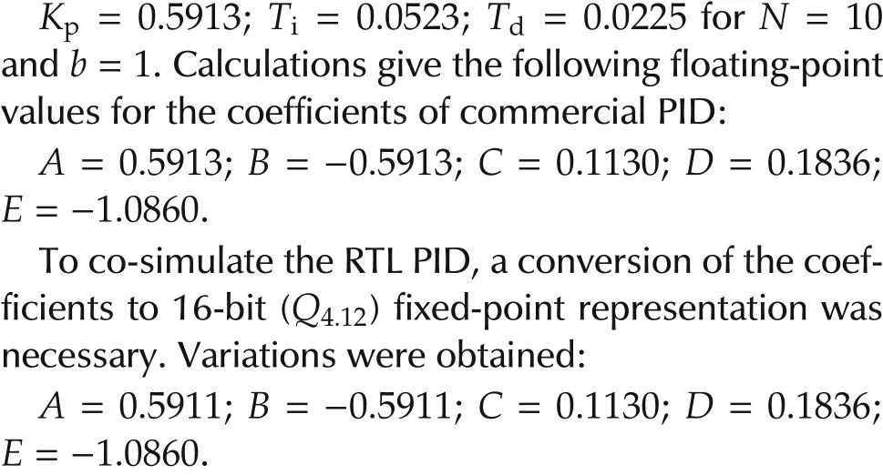
Note that to represent the original parameters with full-precision,44 bits are needed for the fractional part.Varied simulations were performed to verify the correctness of the PID RTL code.First,to explore the precision effect on control quality,the control output of PIDs with various fractional-part sizes(Q4.4,Q4.12,Q4.20)were compared to that of the MATLAB floating-point PID component(Fig.10).Simulation shows different rise-times for different precisions.The higher is the precision;the closer is the control output from the ideal model.The second simulation tests the behavior of the PID after having reached the steady state(Fig.11).For that,two perturbations are successively exerted on control output and on the plant measure.Each time the system recovers as expected.Moreover,finally,the third simulation investigates the PID capabilities to track set-points of arbitrary amplitudes and durations(Fig.12).
After a successful functional verification,the RTL code of PID was synthesized,placed,and routed on Xilinx’s FPGA(Virtex-2).The three preceding co-simulations but with timing backannotation were performed again as a last necessary software verification step before hardware integration of the PID into an FPGA evaluation board(MEMEC V2MB1000).
Finally,as an ultimate validation step,a physical test of our PIDs is performed.We built up a classical temperature control setup(Figs.13 and 14),which consists in a tube comprising a halogen lamp(12V,21W),a temperature sensor(LM35),and a DC Fan(12V,1.68W).Temperature regulation inside the tube is achieved by controlling either the intensity of the lamp,or the rotation speed of the fan.This is carried out by the use of two PWMs,whose duty-cycle ratios represent the PID controller output(u(k)).These two PWMs do not act directly on the fan or on the lamp but rather on transistors(IRF540)that control the power consumed by the lamp and fan.
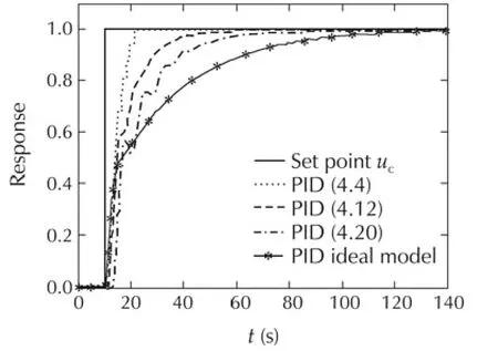
Fig.10 Fixed-point versus floating-point.

Fig.11 Perturbations after steady-state on control-output and on plant measure,successively.
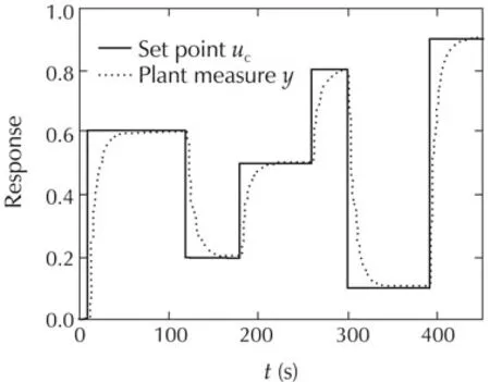
Fig.12 Set-point tracking of arbitrary amplitudes and durations.
The sensing of the actual temperature of the tube is assured by LM35 component which delivers a voltage value that grows linearly with temperature(1.5V corresponds to 150◦C).As the maximum voltage allowed by FPGA evaluation board(V2MB1000)is 3.3V,the calculation of the real temperature(T)is done as follows:T=[(val_opb_ADC×3.3)/1023]×100.This allows a temperature control with a minimum step of 0.32◦C.
The V2MB1000 board is connected through RS232 port to a PC running a.net application which allows a real-time display of the temperature as well as an instantaneous tuning of the set-point.
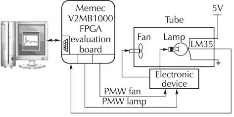
Fig.13 Synoptic scheme of the setup.
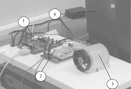
Fig.14 Setup of temperature regulation.①:FPGA evaluation board;②:Electronic device;③:Tube containing a fun and a lamp;and④:PC display screen.
8 The FWL effect
Fixed-point arithmetic is employed as an approximation of real numbers(floating-point),with a fixed bitlength of the word used to represent data(finite wordlength).This limitation leads to performance degradation(FWL effect)mainly due to quantization of coefficients(parametric errors)and roundoff errors subsequently cumulated during the computation process(numeric noise).In fact,the FWL effect is more-or-less exaggerated depending on the control algorithm used(I/O relationship,levels of parallelism,etc.)as well as on the way the computations are performed(number of bits,different/unique fixed point position,round/truncation,etc.).Compared to the reference floating-point implementation,the FWL effect can be assessed using some indicators such as transfer function sensitivity,or pole sensitivity[40–42].
In fact, the objective is twofold: we need to provide an optimal ASIC/FPGA implementation of FWL PID without degrading control performances. To achieve such a goal,a double expertise is required in hardware design and control system.However,usually,hardware designers do not master control system design,and control system experts do not have the required skills to implement and evaluate the controllers using ASIC/FPGAs[17,43].This is why we propose,as hardware designers,a highly reconfigurable(n,r)and technology-independent FWL PID that can systematically respond to control-engineer demands after having modelled,simulated,and evaluated the performances provided by different bit-width fixed-point representations using MATLAB/Simulink environment,and finally opted for an appropriate wordlength(n)of the setpoint.As for latency value(r),it depends on the application domain and intended objectives.Precise guidelines on how to chooservalue were given in Section 6.
Now that(n,r)couple is known,the FWL problem is tackled from hardware side by simply adjusting in the RTL code the two compile-time constants:setpoint bitsize(n)and latency(r).The synthesis of such a PID generates an optimal structure that not only meets the performances specified by control-engineers,but also consumes minimum power and hardware resources.This would not have been possible without the use of the new highly serialisable multi-bit multiplication algorithm(equation(13)).The incorporation of equation(13)[25]into equations(1)and(2)as an efficient PID engine,allows the generation of PID architectures classified as regular iterative architectures(RIA)[44],known for their high conformity with the principles of regularity and locality.In addition to equation(13),we propose in[25]several new highly serialisable multiplication algorithms,offering different features in power,space and delay,depending on the operand size(n).Reader is encouraged to explore these algorithms[25]to select the appropriate one that leads to best performances of its controller with regard to the size(n)of the setpoint.
Regularity and locality are two important features,highly sought in hardware design as they lead to an important gain in space and delay.Regularity is a general space feature, where the repetitiveness of just one or few elementary building-blocks(mux,adders and shifters of ODMAC,Fig.9)and their interconnection scheme(predefined netlist)suffice to draw the whole architecture(MAC/ODMAC and then PID).In the other hand,locality is both space and time feature,in the sense where each building-block can only interact with its nearest surrounding neighbours,and any transaction from one building-block to the next is completed in one and only one unit time delay(clock period).Because of these two important features,our PIDs can be finely grained at bit level in space(setpoint bit-sizen,latencyr)and unit delay in time(latencyr).
Experimental results depicted in Fig.15 illustrate the FWL effects on temperature regulation.Reducing the fractional-part size of the set-point beyond a certain limit(4 bits)yields to a continuous fluctuation of the temperature inside the tube(Fig.15(d)).The best compromise is a 6-bit fractional-part(Fig.15(c))which ensures a correct regulation while consuming less power and hardware resources.As temperature regulation system has a very slow dynamic,speed is not a concern.Therefore,the most appropriate PID in this case is PIDX_1 as it is the least power consumer.Adversely,for very fast dynamic systems,such as MEMS[45]or microrobotics applications[46],PIDX_n/2 is the most adequate option as it leads to the highest control rate.
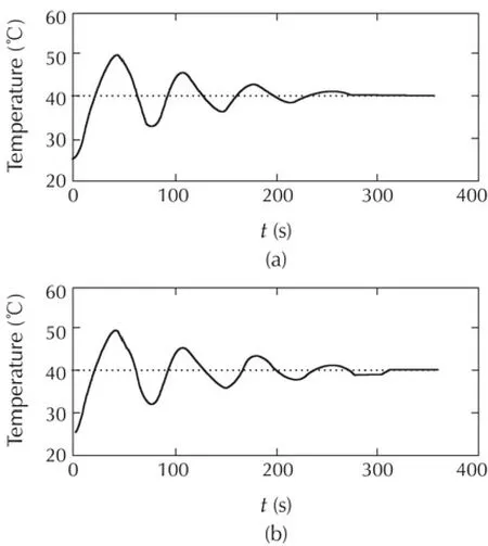
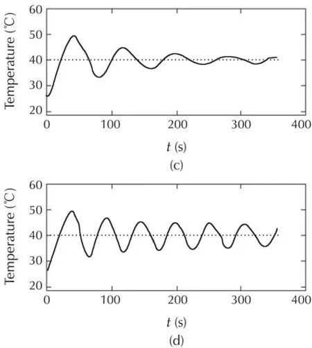
Fig.15 Effect of the setpoint fractional length on temperature regulation.(a)Floating point PID;(b)our PID with Qni.nf=Q8.8;(c)our PID with Qni.nf=Q8.6;and(d)our PID with Qni.nf=Q8.4.
9 Conclusions
Despite the large popularity of PID controller,little attention has been paid to its optimization,either for ASIC or for FPGA integration.To break down this paradoxical situation,a series of high-speed and low-power PIDs,especially dedicated to embedded applications was proposed.They are based on two discrete forms of PID algorithm:the incremental form and the commercial form,both with constant and time-varying coefficients.The work focused more particularly on the commercial form with varying coefficients as it is the most used in industry due to the higher control-quality provided.Two types of optimizations were carried out:architectural and algorithmic optimizations.The former is a macro-level optimization,based on an efficient partitioning of PID discrete-equations,considering the double MAC(DMAC=XY+ZT)as the main building block of PID architecture.An optimized version of DMAC was developed(ODMAC)for less hardware resource occupation.As for the micro-level optimization(inner optimization of ODMAC),three multiplication algorithms were experienced:BMA,MBMA,and a new general and recursive version of MBMA called RMRMA.In addition,some low-power design techniques were incorporated,such as sleep mode,and step-by-step sign-propagation technique.
The implementation results of PID based upon these three algorithms yielded to gradual improvements with a clear superiority over results presented in[21].For instance,concerning PID1_2 and PID1_4,savings of 177%,23%,and 36%,and savings of 284%,14%,and 26%are obtained in control-rate,power consumption,and total gate count,respectively.Additionally,analytical scaling-complexity evaluations with respect to the couple(n,r),confirmed also by software simulations,revealed useful information which is summarized as follows:
·PIDX_n/2 is the fastest PID that yields to the highest control-rate(30MHz for PID2_8 mapped on Virtex6,with(n,r)=(16,8));
·PIDX_1 is the most power efficient PID when speed is not a concern;
·PIDX_n and PIDX_n/2 are the most efficient PIDs when both high control-rate and low-power dissipation are required.
Further extension to the present work is to apply the same(or appropriate)partitioning in conjunction with RMRMA algorithm to the set of recurrent equations of an arbitrary number of multi-loop PID controllers taken as a whole.
Finally,the new recursive multiplication algorithm(RMRMA),well adapted to large word-lengths,and which was behind the drastic optimization of PID,can be efficiently applied to a variety of advanced control algorithms such as to linear-quadratic-gaussian(LQG)or sliding-mode controllers,etc.
[1]K.Åström,T.Hägglund.PID Controllers:Theory,Design,and Tuning.2nded.by the Research Triangle Park:Instrument Society of America,1995.
[2]D.Xue,Y.Chen,D.P.Atherton.Linear Feedback Control.Philadelphia:Society for Industrial and Applied Mathematics(SIAM),2007.
[3]X.Shao,D.Sun,J.K.Mills.A new motion control hardware architecture with FPGA based IC-design for robotic manipulators.IEEE International Conference on Robotics and Automation(ICRA).New York:IEEE,2006:3520–3525.
[4]J.S.Kim,H.W.Jeon,S.Jeung.Hardware implementation of nonlinear PID controller with FPGA based on floating point operation for 6-DOF manipulator robot arm.International Conference on Control,Automation and Systems(ICCAS).Piscataway:IEEE,2007:1066–1071.
[5]L.Qu,Y.Huang,L.Ling.Design and implementation of intelligent PID controller based on FPGA.Proceedings of the 4th International Conference on Natural Computation(ICNC).Piscataway:IEEE,2008:511–515.
[6]M.Keating,P.Bricaud.Reuse Methodology Manual for System on a Chip Designs.3rd ed.New York:The Kluwer Academic Publishers,2002.
[7]International Technology Roadmap for Semiconductors.ITRS Reports,2007/2008:http://www.itrs.net/reports.html.
[8]T.Hilaire,P.Chevrel,J.F.Whidborne.A unifying framework for finite wordlength realizations.IEEE Transactions on Circuits and Systems,2007,54(8):1765–1774.
[9]T.Hilaire,D.Ménard,O.Sentieys.Bit accurate roundoff noise analysis of fixed-point linear controllers.Proceedings of the IEEE International Conference on Computer-Aided Control Systems(CACSD).New York:IEEE,2008:607–612.
[10]S.Gretlein,G.Garcia,J.Sumner.DSPs,microprocessors and FPGAs in control.Magazineof Recordforthe Embedded Computing Industry(RTC Magazine),2006:http://www.rtcmagazine.com/articles/view/100495.
[11]E.Manmasson,L.Idkhajine,M.N.Cirstea,et al.FPGA in industrial control applications.IEEE Transactions on Industrial Informatics,2011,7(2):224–243.
[12]S.Chander,P.Agarwal,I.Gupta.FPGA-based PID controller for DC-DC converter.Proceedings of the IEEE Joint International Conference on Power Electronics,Drives and Energy Systems(PEDES).Piscataway:IEEE,2010.
[13]S.Yang,M.Gao,J.Lin,et al.The IP core design of PID controller based on SOPC.Proceedings of the IEEE International Conference on Intelligent Control and Information Processing.Piscataway:IEEE,2010:363–366.
[14]J.Lazaro,A.Astarloa,J.Arias,et al.Simulink/Modelsim simulable VHDL PID core for industrial SoPC multiaxis controllers.Proceedings of the IEEE 32nd Annual Conference on Industrial Electronics(IECON).Piscataway:IEEE,2006:3007–3011.
[15]F.Fons,M.Fons,E.Canto.Custom-made design of a digital PID control system.Proceedings of the IEEE International Conference on Acoustics,Speech and Signal Processing(ICASSP).Piscataway:IEEE,2006:1020–1023.
[16]B.V.Sreenivasappa,R.Y.Udaykumar.Design and implementation of FPGA based low power digital PID controllers.Proceedings of the IEEE International Conference on Industrial and Information Systems(ICIIS).New York:IEEE,2009:568–573.
[17]J.Lima,R.Menotti,J.M.P.Cardoso,et al.A methodology to design FPGA-based PID controllers.Proceedings of the IEEE International Conference on Systems,Man and Cybernetics.Piscataway:IEEE,2006:2577–2583.
[18]I.Urriza,L.A.Barragan,J.I.Artigas,et al.Word Length Selection Method based on Mixed Simulation for Digital PID Controllers Implemented in FPGA.Proceedings of the IEEE International Symposium on Industrial Electronics(ISIE).Piscataway:IEEE,2008:1965–1970.
[19]W.Zhao,B.H.Kim;A.C.Larson,et al.FPGA implementation of closed-loop control system for small-scale robot.Proceedings of the IEEE 12th International Conference on Advanced Robotics(ICAR).Piscataway:IEEE,2005:70–77.
[20]L.Samet,N.Masmoudi,M.W.Kharrat,et al.A digital PID controller for real-time and multi-loop control:a comparative study.Proceedings of the IEEE International Conference on Electronics,Circuits,and Systems(ICECS).Piscataway:IEEE,1998:291–296.
[21]Y.Fong,M.Moallem,W.Wang.Design and implementation of modular FPGA-based PID controllers.IEEE Transactions on Industrial Electronics,2007,54(4):1898–1906.
[22]B.Wittenmark,K.J.Astrom,K.E.Arzenin.Computer Control:An Overview.Lund,Sweden:Lund Institute of Technology,2003:http://www.control.lth.se/kursdr/ifac.pdf.
[23]A.D.Booth.A signed binary multiplication technique.The Quarterly Journal of Mechanics and Applied Mathematics,1951,4(2):236–240.
[24]O.L.MacSorley.High-speed arithmetic in binary computers.Proceedings of the IRE,1961,49(1):67–91.
[25]A.K.Oudjida,N.Chaillet,A.Liacha,et al.A New recursive multibit recoding algorithm for high-speed and low-power multiplier.Journal of Low Power Electronics(JOLPE),2012,8(5):1–16.
[26]A.K.Oudjida,N.Chaillet,A.Liacha,et al.High-speed and lowpower PID structures for embedded applications.Proceedings of the 21st Edition of the International Workshop on Power and Timing Modeling,Optimization and Simulation PATMOS.Berlin:Springer-Verlag,2011:257–266.
[27]Y.H.Seo,D.W.Kim.A new VLSIarchitecture of parallel multiplier-accumulator based on radix-2 modified Booth algorithm.IEEE Transactions on Very Large Scale Integration(VLSI)Systems,2010,18(2):201–208.
[28]L.P.Rubinfield.A proof of the modified booth algorithm for multiplication.IEEE Transactions On Computers,1975,24(10):1014–1015.
[29]H.Sam,A.Gupta.A generalized multibit recoding of two’s complement binary numbers and its proof with application in multiplier implementations.IEEE Transactions on Computers,1990,39(8):1006–1015.
[30]F.Lamberti.Reducing the computation time in(short bit-width)two’s complement multiplier.IEEE Transactions on Computers,2011,60(2):148–156.
[31]S.R.Kuang,J.Wang,C.Guo.Modified booth multipliers with a regular partial product array.IEEE Transactions on Circuit and Systems,2009,56(5):404–408.
[32]J.Kang,J.L.Gaudiot.A simple high-speed multiplier design.IEEE Transactions on Computers,2006,55(10):1253–1258.
[33]D.Crookes,M.Jiang.Using signed digitarithmetic for low-power multiplication.Electronics Letters,2007,43(11):613–614.
[34]P.M.Seidel,L.D.McFearin,D.W.Matula.Secondary radix recodings for higher radix multipliers.IEEE Transactions on Computers,2005,54(2):111–123.
[35]R.C.North,W.Ku.β-bit serial/parallel multipliers.Journal of VLSI Signal Processing,1991,2(4):219–233.
[36]D.A.Henlin,M.T.Fertsch,M.Mazin,et al.A 16 bit×16 bit pipelined multiplier macrocell.IEEE Journal of Solid-State Circuits,1985,20(2):542–547.
[37]J.S.Kelly,V.S.Rao,H.J.Pottinger,et al.Design and implementation of digital controllers for smart structures using field programmable gate arrays.Smart Material Structure Journal,1997,6(5):559–572.
[38]L.Shang,A.S.Kaviani,K.Bathala.Dynamic power consumption in Virtex-II FPGA family.Proceedings of the ACM/SIGDA 10th International Symposium on Field-programmable Gate Arrays.Monterey:ACM,2002:157–164.
[39]Xilinx Inc.Virtex6 FPGA:Satisfying the Insatiable Demand for Higher Bandwidth,2009.http://www.xilinx.com/publications/prod_mktg/Virtex6_Product_Brief.pdf.
[40]M.Gevers,G.Li,Parametrizations in Control,Estimation and Filtering Probems.Berlin:Springer-Verlag,1993.
[41]T.Hilaire,P.Chevrel.Sensitivity-based pole and input-output errors of linear filters as indicators of the implementation deterioration in fixed-point context.EURASIP Journal on Advances in Signal Processing.Special Issue on Quantization of VLSI Digital Signal Processing Systems,2011:DOI 10.1155/2011/893760.
[42]B.Lopez,T.Hilaire,L.S.Didier.Sum-of-products evaluation schemes with fixed-point arithmetic,and their application to IIR filter implementation.Proceedings of the International Conference on Design and Architecture for Signal and Image Processing(DASIP).New York:IEEE,2012:1–8.
[43]M.Petko,G.Karpiel.Semi-automatic implementation of control algorithms in ASIC/FPGA.Proceedings of Emerging Technologies and Factory Automation Conference(ETFA’03).New York:IEEE,2003:427–433.
[44]S.K.Rao,T.Kailath.Regular iterative algorithms and their implementation on processor arrays.Proceeding of the IEEE,1988,76(3):259–269.
[45]G.Hoover,F.Brewer,T.Sherwood,et al.Towards understanding architectural tradeoffs in MEMS closed-loop feedback control.Proceedings of the International Conference on Compilers,Architecture,and Synthesis for Embedded Systems(CASES’07).Salzburg:ACM,2007:95–102.
[46]R.Casanovaetal.Integartion of the control electronics for a mm3-sized autonomous microrobot into a single chip.Proceedings of the IEEE International Conference on Robotics and Automation(ICRA).Kobe:IEEE,2009:3007–3012.
11 June 2012;revised 1 April 2013;accepted 2 April 2013
DOI10.1007/s11768-014-2131-5
†Corresponding author.
E-mail:a_oudjida@cdta.dz.Tel.:+213-21-351018;fax:+213-21-351039.
Appendix
1)Incremental form.
The standard version of PID controller id described in a differential equation as
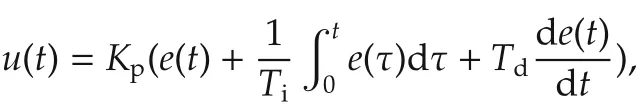
whereeis the system error(e(t)=uc(t)−y(t)),ucis the command signal(setpoint),yis the process variable(measured variable).Kpis the proportional gain,Tithe integration time constant,andTdthe derivative time constant of the controller.Using Laplace transform,u(t)is expressed ins-domain by
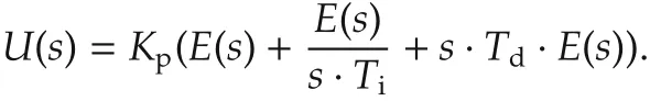
For a small sample intervalTs,the continuous time variable
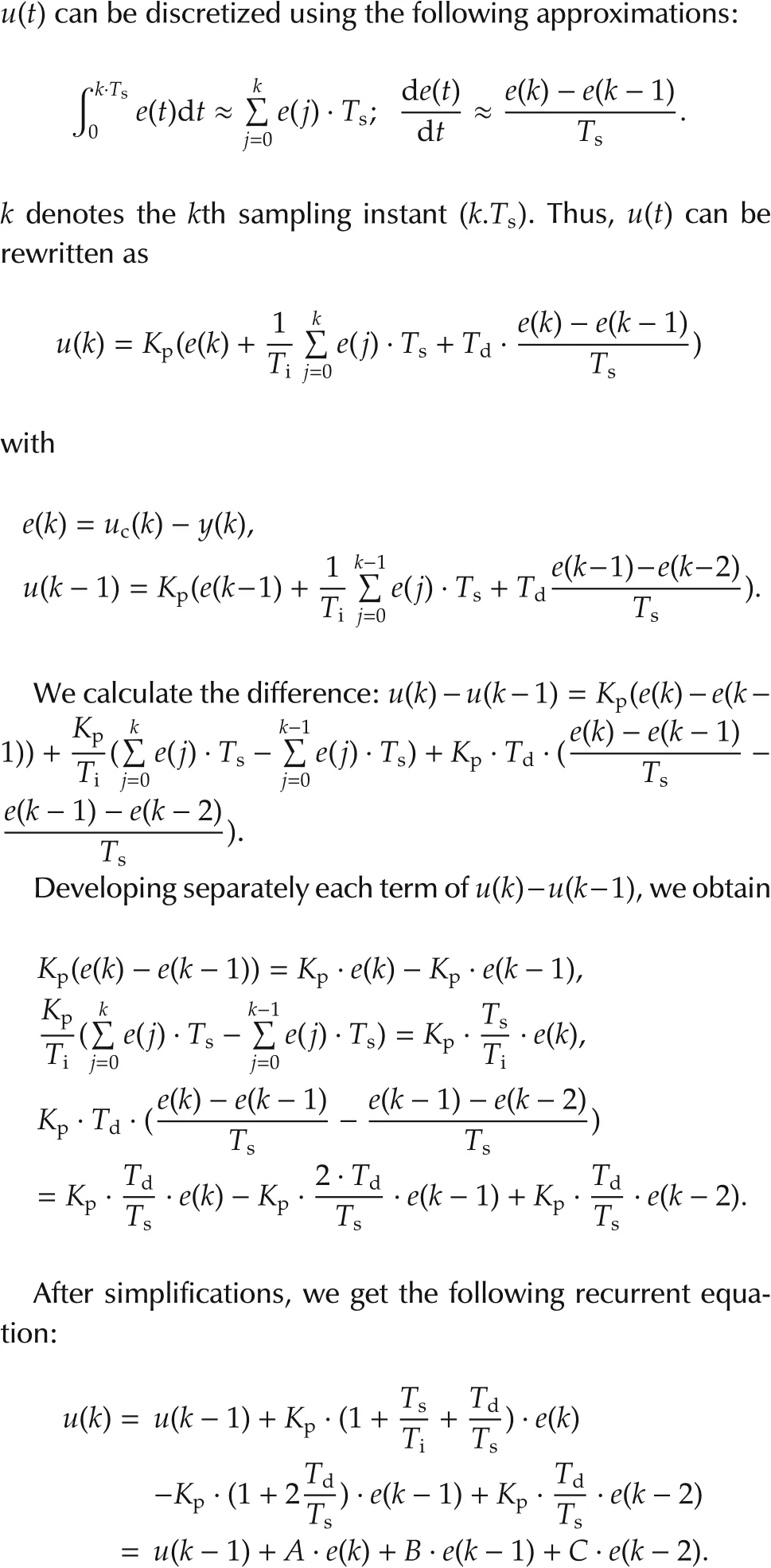
This latter equation is called the incremental form of the controller.A drawback with the incremental algorithm is that it cannot be used for P or PD controllers.
2)Commercial form.
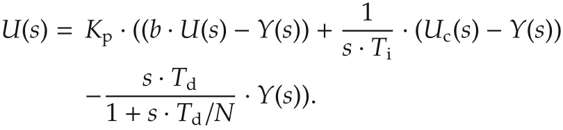
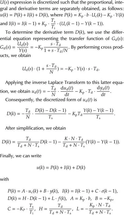
For better performances of PID,two corrections are performed:limitation of the derivative gain and setpoint weighting.A pure derivative action will induce a very large amplification of measurement noise.The gain of the derivative must thus be limited.This can be done by approximating the transfer functions·Tas follows:s
dwhereNis typically in the range of 3 to 20.In addition,to avoid sudden overshoots due to high variations of the setpoint,only a fractionbofucacts on the proportional part(b.uc−y).Hence,the improved PID algorithm becomes

Abdelkrim Kamel OUDJIDAreceived his B.S.degree in Computer Engineering from the Institut National d¯Informatique,INI,Algiers,Algeria,in 1989.He joined the Centre de Developpement des Technologie Avancées,CDTA,Algiers in 1990.Since then,he has been working on the design of high-speed and low-power digital circuits.He is team leader specialized in digital IP design and verification.He is currently preparing a Ph.D.at Franche-Comté University,UFC,Besan¸con,France,under the supervision of Prof.Nicolas Chaillet.His current work focuses on optimization of arithmetic algorithms for the development of high-speed and lowpower finite-word-length controllers,dedicated to micromanipulation applications.E-mail:a_oudjida@cdta.dz.

Nicolas CHAILLETreceived his B.S.degree in Electrical Engineering from the Ecole Nationale Supérieure de Physique,Strasbourg,France,in 1990,and the Ph.D.degree in Robotics and Automation from the University Louis Pasteur,Strasbourg,France,in 1993.In 1995 he became associate professor at the University of Franche-Comté in Besan¸con,France.Since 2001,he is a professor at the University of Franche-Comté and is since 2012 the Director of the FEMTO-ST Institute.His research interests are in microrobotics and more generally in micromechatronics fields,especially in micromanipulation,microgrippers,smart materials,microactuators,smart microstructures and the design and implementation of their control.E-mail:nicolas.chaillet@femto-st.fr.

Ahmed LIACHAreceived his B.S.degree in Electronics from the Université des Sciences et de la Technologie,Houari Boumediène,Algiers,Algeria,in 2002.In 2004 he joined the department of microelectronics at the Centre for Development of Advanced Technologies,CDTA,where he is currently a digital IP designer for industrial control applications.E-mail:liacha@cdta.dz.

Mohamed Lamine BERRANDJIAreceived his B.S.degree in Computer Science Engineering from the University of Mantouri,Constantine,Algeria,in 2003.Since 2005,he is research assistant at Centre de Développement des Technologies avancées,CDTA,Algiers,Algeria,where he specialized in digital IP design and embedded systems for FGPA.E-mail:mberrand-——- ——– jia@cdta.dz.

Mustapha HAMERLAINreceived the Doctorate degree in 1993 from National Institute of Applied Sciences of Toulouse(France).He is currently the head of the robotics department of the Advanced Technologies and Development Center(CDTA)of Algiers,and professor at the school(EMP).From 1988 to 1993 he was involved in a research project in the field of robotics PAM(Pneumatic Artificial Muscles)as a researcher in the National Institute of Applied Sciences(INSA)of Toulouse.His current research interests include robust control of nonlinear systems,robot motion control,visual control,robots manipulators and pneumatic artificial muscles actuators.E-mail:mhamerlain@cdta.dz.
 Control Theory and Technology2014年1期
- Control Theory and Technology的其它文章
- Constrained optimal steady-state control for isolated traffic intersections
- Capture condition for endo-atmospheric interceptors steered by ALCS and ARCS
- Distributed attitude synchronization using backstepping and sliding mode control
- Non-Zenoness of piecewise affine dynamical systems and affine complementarity systems with inputs
- Frequency-domain L2-stability conditions for time-varying linear and nonlinear MIMO systems
- Control of a flexible rotor active magnetic bearing test rig:a characteristic model based all-coefficient adaptive control approach