
Control of a flexible rotor active magnetic bearing test rig:a characteristic model based all-coefficient adaptive control approach
2014-12-07 05:13:32LongDIZongliLIN
Control Theory and Technology 2014年1期
Long DI,Zongli LIN
Charles L.Brown Department of Electrical and Computer Engineering,University of Virginia,P.O.Box 400743,Charlottesville,VA 22904-4743,U.S.A.
Control of a flexible rotor active magnetic bearing test rig:a characteristic model based all-coefficient adaptive control approach
Long DI,Zongli LIN†
Charles L.Brown Department of Electrical and Computer Engineering,University of Virginia,P.O.Box 400743,Charlottesville,VA 22904-4743,U.S.A.
Active magnetic bearings(AMBs)have found a wide range of applications in high-speed rotating machinery industry.The instability and nonlinearity of AMBs make controller designs difficult,and when AMBs are coupled with a flexible rotor,the resulting complex dynamics make the problems of stabilization and disturbance rejection, which are critical for a stable and smooth operation of the rotor AMB system,even more difficult.Proportional-integral-derivative(PID)control dominates the current AMB applications in the field.Even though PID controllers are easy to implement,there are critical performance limitations associated with them that prevent the more advanced applications of AMBs,which usually require stronger robustness and performance offered by modern control methods such as H-infinity control and μ-synthesis.However,these advanced control designs rely heavily on the relatively accurate plant models and uncertainty characterizations,which are sometimes difficult to obtain.In this paper,we explore and report on the use of the characteristic model based all-coefficient adaptive control method to stabilize a flexible rotor AMB test rig.In spite of the simple structure of such a characteristic model based all-coefficient adaptive controller,both simulation and experimental results show its strong performance.
Active magnetic bearings;Adaptive control;Characteristic modeling;Flexible rotor;Robustness
1 Introduction
Active magnetic bearings(AMBs)has been an active subject of research for decades and are becoming popular in practical applications.AMBs compare very differently with conventional mechanical bearings.On the one hand,AMBs rely on electromagnetic forces to suspend the rotor.There is no physical contact between the bearings and the rotor,creating an operation environment that is free of friction.On the other hand,AMBs require feedback control to generate appropriate supporting forces.Control of AMBs involves not onlysophisticated electronic devices,but also the design of the control algorithm,which often time has to be sophisticated as well.Thus,even though AMBs have several advantages over conventional mechanical bearings,such as lower power losses,oil free operation and improved maintainability,they are more sophisticated because of the difficulties associated with the design and implementation of their control systems.
PID control has been the most widely used control method in industrial applications of AMB systems[1].Because of their simplicity,PID controllers are easy to implement and can be tuned intuitively.A properly tuned PID controller is able to achieve reasonable control performance.However,for systems with complex dynamics,such as flexible rotor AMB systems,it is difficult for PID controllers to deliver the required robust performance.In recent years,robust control design methods,such as μ-synthesis,have also been applied in AMB applications[2,3].Compared with the PID control design,the μ-synthesis approach is able to better handle the uncertainties in the complex system and achieve reliable performance.However,μ-synthesis requires a relatively accurate characterization of the plant dynamics and uncertainties,which in reality is often difficult to obtain.Furthermore,if the properties of the plant change significantly,the μcontroller designed based on the characterization of the original plant and uncertainties might fail to perform properly.
Characteristic model based all-coefficient adaptive control method has been widely used in process control and aerospace industry.Several real world applications have demonstrated its effectiveness(see,for example,[4–7]).In comparison with the conventional adaptive control,characteristic model based all-coefficient adaptive control has fewer coefficients to estimate and the controller structure is simpler.Despite its simplicity,the characteristic model based all-coefficient adaptive control is able to provide robust control performance on multi-dimensional complex dynamical systems,without requiring the actual plant models[8–10].
This paper explores and reports on the use of the characteristic model based all-coefficient adaptive control method to stabilize a flexible rotor AMB test rig.Both the simulation and experimental results demonstrate strong potential for the application of the characteristic model based all-coefficient adaptive control in AMB applications.
The remainder of the paper is organized as follows.Section 2 describes the flexible rotor AMB test rig,its modeling,and a previously developed μ-synthesis controller as a benchmark for comparison.Section 3 briefly describes the characteristic model based all-coefficient adaptive control design method.Section 4 presents the implementation of the characteristic model based all coefficient adaptive control on the test rig and shows both simulation and experimental results.Conclusions are drawn in Section 5.
2 The flexible rotor AMB test rig
2.1 Description of the test rig
Our flexible rotor AMB test rig[11]was designed and built as a research platform in the Rotating Machinery and Control(ROMAC)Laboratory at University of Virginia.The purpose of this test rig is to emulate an industrial centrifugal gas compressor and study control of the rotordynamic instability and supercritical operation as shown in Fig.1.The two radial support AMBs are located at the two ends of the rotor.Disks 1 and 2 on the rotor simulate the blades in a compressor and the two exciter AMBs in the middle and quarter spans of the rotor synthesize various effects on the rotor,such as the cross coupling effect of a seal.When the rotating speed increases,the disks will generate the gyroscopic effect which may cause instability in the rotordynamic.The load-dependent cross-coupled stiffness(CCS),which can be emulated by an exciter AMB,is another cause of performance degradation and instability.
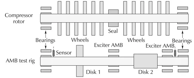
Fig.1 Motivation for the design of the test rig.
The rotor is 1.23m long and weighs around 44.9kg.Four laminated steel journals are mounted on the shaft for the two radial support AMBs at the non-driven end(NDE)and driven end(DE)and the two radial exciter AMBs at the middle and quarter spans.The air gaps at all the four AMBs are the same at 10 mils. Only the NDE and DE support AMBs are utilized for control.There are also two auxiliary ball bearings mounted at the support AMB locations to prevent damage to AMBs when the rotor drops.A 3.7kW,electric fan cooled,high speed motor with variable frequency drive(VFD),Colombo RS-90/2,is adopted that is able to run the rotor to 18,000r/min.In order to obtain the approximate locations of the critical speeds as a function of the support stiffness,we performed rotordynamic analysis and the resulting undamped critical speed map is shown in Fig.2.
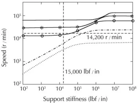
Fig.2 The undamped critical speed map of the rotor.
In the undamped critical speed map,the first bending critical speed,shown in the curve with circles,starts at 13,227r/min(220.4Hz)and increases with the increase of the support stiffness.Usually the target closed-loop stiffness for an AMB system is 2.684×10⁶N/m for rotors of comparable dimensions[11].Based on this map,we can predict the speeds at which the unbalance distribution of the rotor will lead to the excitation of the rotor’s natural frequencies.
Another important graphic tool for rotordynamic analysis is the free-free mode shape plot,which is shown in Fig.3 for our test rig.It illustrates the movement of the rotor at the rigid body modes and bending critical modes with respect to the locations of the position sensors and actuators.Based on this plot,we can determine if the axial locations of the sensors and AMBs are in the proper positions to avoid the out of phase situation as the rotor runs through various bending critical speeds.
Four amplifiers are installed for each radial AMB and each amplifier features a 25kHz switching frequency.The maximum continuous current is rated at 10 A, which gives each AMB a static load capacity of 1450N.The rotor motion is monitored by a 10 channel Kaman eddy current sensor system and the displacement of each control axis is measured by a 1H/15N static probe.The digital control system is based on an Innovative Integration M6713 PCI board and a TI C6713B 32-bit floating point digital signal processing(DSP)chip is used for the implementation of the digital control algorithm with an updating frequency at 12kHz.Sixteen input-output analog channels are simultaneously sampled and interfaced with the 16 sensors and the 16 actuators associated with the four AMBs.A computer control station with a custom designed graphic user interface provides the user with many functionalities.The entire flexible rotor AMB test rig is shown in Fig.4.
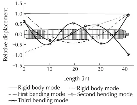
Fig.3 The free-free mode shape plot of the rotor.
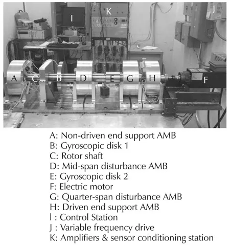
Fig.4 An overview of the flexible rotor AMB test rig.
2.2 Modeling and μ synthesis control
A diagram of the overall flexible rotor AMB control system is shown in Fig.5.The dynamics of the test rig is very complex.Several components are involved in the modeling process.A rotor model is derived based on the finite-element analysis method.The shaft length is divided into 50 stations for the lateral rotordynamic modeling.For the magnetic bearings,a linearized magnetic circuit model is adopted.The sensors,anti-aliasing filters(AAF)and amplifiers are described by their transfer functions.The combined model of the overall test rig has 452 states.Since higher modes beyond the third bending critical frequency contribute negligible effects on the entire system dynamic response,they are truncated and the final reduced order model possesses 36 states with 4 inputs and 4 outputs at the driven end(xaxis(DEX)andyaxis(DEY))and the non-driven end(xaxis(NDEX)andyaxis(NDEY)).This 36th order model serves as the nominal model of the test rig.
Shown in Fig.6 is the Bode plots of one of the four control channels in the nominal model of the test rig.Overlaid on these Bode plots are the experimental measurements of the transfer function of the same channel.The agreement between the analytic model and the experimental measurements in the frequency range of 1 Hz to 1kHz confirms the accuracy of the analytic model we have obtained.
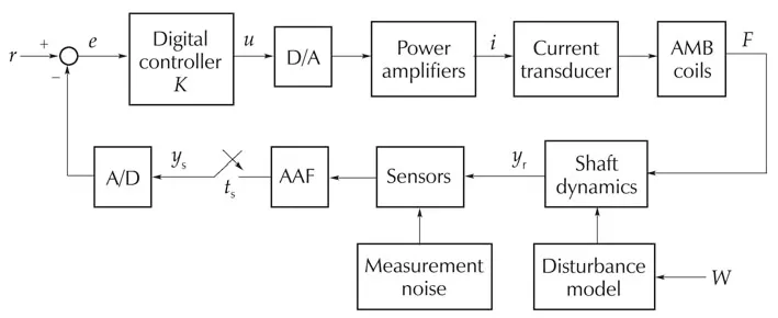
Fig.5 A diagram of the flexible rotor-AMB control system.
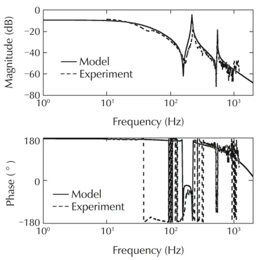
Fig.6 Bode plots of the test rig: analytic model vs experimental measurements.
A realistic characterization of the uncertainties is essential in the design of a μ-synthesis controller.We have identified two major sources of uncertainties in our test rig.The first one is the gyroscopic effect,which varies with the rotating speed.The main influence of the gyroscopic effect is to split the system eigenvalues into forward and backward modes with different natural frequencies.Shown in Fig.7 is the Campbell diagram with a support stiffness of 5×10⁶N/m,depicting the variation of the system eigenvalues with the increase of the rotating speed.Also marked in the figure is the maximum continuous operating speed(MCOS)of 18,000r/min,which represents the capacity limit of the motor drive.
The other major source of uncertainty is the cross coupled stiffness(CCS),which depends heavily on the load of the rotor.A pole-zero map of the open-loop rotor AMB system at 0r/min under the effect of the CCS is shown in Fig.8.In this pole-zero map,originally two unstable real poles corresponding to the first two rigid body modes lie in the right-half plane(RHP)and four complex pole-zero pairs corresponding to the first two bending modes lie in the left-half plane near the imaginary axis. The CCS drives the first rigid body mode(Nc1)in the RHP to split into two complex conjugate poles,which move to the further right as the CCS increases.The complex pole-zero pairs corresponding to the first bending mode(Nc3)move to the RHP as the arrow sign indicates.Those changes increase the minimum achievable peak sensitivity and introduce additional phase lags
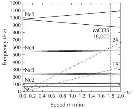
Fig.7 A Campbell diagram that characterizes the uncertainty in the gyroscopic effect.
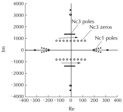
Fig.8 Uncertainty characterization for cross-coupled stiffness.
Basedon the nominal model of the test rig and the uncertainty characterization,a μ-synthesis controller has been designed in[3,12].The design utilizes the Matlab function dksyn to carry out four D-K iterations and arrive at a reasonable μvalue.The result is a 48th order controller with μ=0.856.The Bode plots of this μ-synthesis controller are shown in Fig.9.Simulation of the closed-loop system under this controller has been carried out in Simulink[3,12].The μ-synthesis design has also been implemented on a DSP computer.Both simulation and experimental results have shown that the μ-synthesis controller achieves satisfactory performance and the parametric uncertainties of the rotor-AMB system have been well handled[12].

Fig.9 Bode plots of the μ-synthesis controller.
The performance of the μ-synthesis controller will serve as a benchmark for comparison with the characteristic model based all-coefficient adaptive control to be presented in the next section.
3 Characteristic model based all-coefficient adaptive control
3.1 Characteristic modeling
Unlike conventional modeling methods that concentrate on the precise system dynamics,the characteristic modeling focuses on the characteristics of the plant and the control performance requirements.The corresponding output information of the original high order plant is compressed into a few characteristic parameters so that no information is lost during the modeling process[5].As a result,even though the characteristic model possesses a simple structure,it precisely reflects the dynamics of the original plant.
It has been established in[5]that a linear time invariant plant
can be represented by a time-varying difference equation with a lower order.The exact order of the difference equation is determined by the control objective.For our purpose in the paper,we recall the following results.
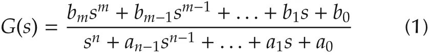
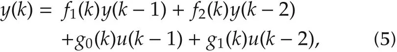
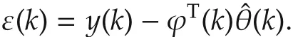
Consider a linear time-invariant plant as given in(1).If the control objective is position keeping or reference tracking,then,for a sufficiently small sampling periodTthat satisfies the sampling theorem and guarantees the controllability of the discretized model,the characteristic model is a second-order time-varying difference equation,
whereu(k)andy(k)are respectively the control input and the system output at the kth sampling point and the coefficientsf1(k),f2(k),g0(k)andg1(k)are the characteristic parameters.
The characteristic model for the plantG(s)as given in(2)possesses the following properties:
·The coefficientsf1(k),f2(k),g0(k)andg1(k)are slowly time-varying.
·The ranges of these parameters can be decided a priori.
·In response to the same input,the output of the original model(1)is identical to the output of the characteristic model(2)at each sampling time.
3.2 Characteristic model based all-coefficient adaptive control
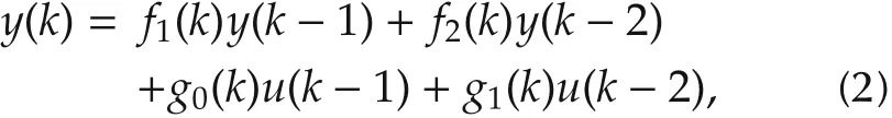
Consider a linear time-invariant plant

Let the discretized equation of(3)be given by
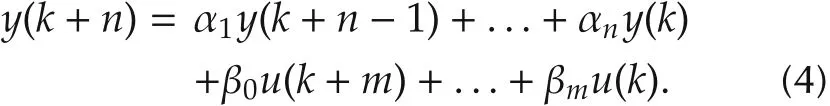
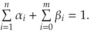
Then,the coefficients of(4)satisfy the following conditions[5]:
·If the static gainDof(3)is equals to unity,then the sum of all the coefficients of(4)equals one,i.e.,
·IfD≠0 and is bounded,then the sum of all the coefficients of(4)approaches one asT→0,i.e.,
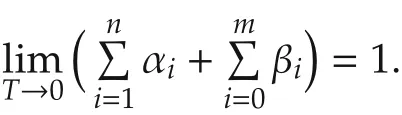
The ranges of αi’s and βi’s can be determined in advance based on the ranges ofai’s andbi’s.The value of the sampling periodT,when system(3)does not have poles at the origin,is usually chosen as[8],

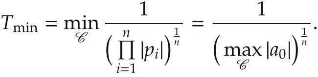
whereTminis the minimum average time constant of system(3)over the ranges of the values of its coefficientsai’s andbi’s.The value ofTmincan be determined in a straightforward way as follows.
LetCdenote the set of values of the coefficientsai’s andbi’s.Clearly,the poles of system(3),denoted aspi,i=1,2,...,n,are functions of the elements ofC.Then,the minimum average time constantTmincan be computed as
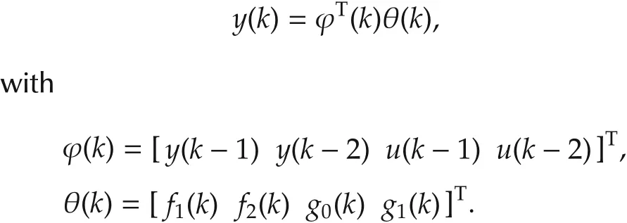
We now consider the characteristic model for system(3),i.e.,
which can be written as follows to facilitate the estimation of its coefficients,
In order to specify the ranges of the values of the coefficients in the characteristic model(5),we consider the following second order time-invariant difference equation
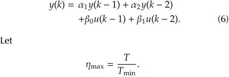
Then,according to[13],when ηmax≤ 1/3,the coefficients in the characteristic model(5)for an unstable plant satisfy the following conditions:

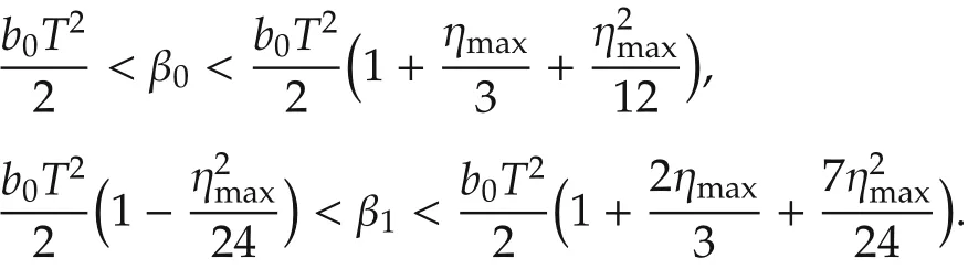
We observe,in the above conditions,that α1→ 2,α2→−1,β0→ 0 and β1→ 0,asT→ 0 and hence ηmax→ 0.
For a particular value of ηmax=1/4,we arrive at the following ranges for the coefficients α1and α2:
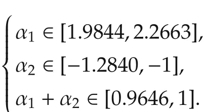
On the other hand,β0andβ1are smaller positive scalars.
Motivated by the above analysis on the second order time invariant difference equation(6),we will limit the coefficientsf1(k)andf2(k)in the characteristic model(5)to the following set:
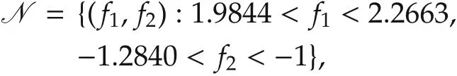
and choose some positive numbers that are much smaller than one as the initial values forg0(k)andg1(k).
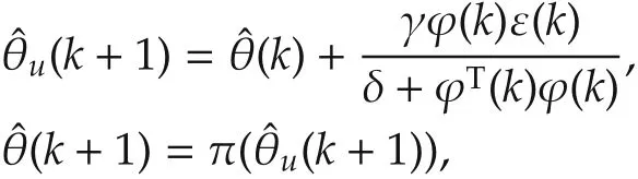
where δ ≥ 0,0 < γ < 2,and,for a scalarx,π(x)is the projection ofxinto the setN[14].
The characteristic model based all-coefficient adaptive controluc(k)is formulated as

whereuc1(k),uc2(k),uc3(k)anduc4(k)are respectively specified as follows:
·Maintaining/tracking control:
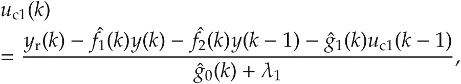
whereyr(k)is the reference system output,λ1is a positive constant,andare the estimates off1(k),f2(k),g0(k)andg1(k),respectively.
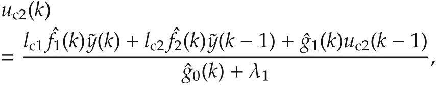
·Golden section adaptive control:
·Differential control:
whered1is a positive constant.
·Integral control:
whered2is a positive constant.
4 Simulation and experimental results on the test rig
In this paper,we explore the application of the characteristic model based all-coefficient adaptive control scheme,as recalled in Section 3,to the flexible rotor AMB test rig described in Section 2.We will carry out both the simulation studies and the experimental testing.
The simulation is based on the Simulink model derived for the entire flexible rotor AMB system,which includes all components of the test rig.The μ-synthesis controller was initially used to stabilize the test rig and its performance serves as a benchmark for comparison with our characteristic model based all-coefficient adaptive controller.
The μ-synthesis controller in Simulink is then replaced with the characteristic model based all-coefficient adaptive controller.An identical characteristic model based all-coefficient adaptive controller is implemented for all the four control channels,thexandyaxes at both the driven and nondriven ends of the rotor.In simulating the characteristic model based all-coefficient adaptive control,the controller parameters are chosen as λ1=0.16,d1=0.0257,d2=0.01,δ =3.5 and γ =1.5.The initial values for the adaptation law are selected asf1(0)=2.102,f2(0)=−1.104 andg0(0)=g1(0)=0.001.Note that(f1(0),f2(0))∈N.
Shown in Figs.10 and 11 are some simulation re-sults for the μ-synthesis controller and the characteristic model based all-coefficient adaptive controller,respectively.For both controllers, the simulation starts with the 0r/min rotating speed.The rotating speed is then gradually increased to 14,400r/min.It can be noticed that for different control channels,the control signals from the characteristic model based all-coefficient adaptive control are very similar to each other due to the fact that an identical controller is applied at each control input.On the other hand,for the μ-synthesis control,the control signals vary significantly from channel to channel.
In terms of the levels of vibration at both the driven and nondriven ends, it can be observed that the displacements in bothxandyaxes are much smaller under the characteristic model based all-coefficient adaptive control law than under the μ-synthesis controller for most of the speed range.The adaptation of the coefficients in the characteristic model based all-coefficient adaptive controller,while the rotating speed varies,is shown in Fig.12.
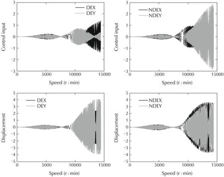
Fig.10 Simulation results with the μ-synthesis controller:control signals and the shaft displacements.

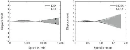
Fig.11 Simulation results with the characteristic model based all-coefficient adaptive controller:control signals and the shaft displacements.

Fig.12 Adaptation of the parameters f1(k),f2(k),g0(k)and g1(k),as the rotating speed varies.
The μ-synthesis controller has been experimentally tested in[12].To implement the characteristic model based all-coefficient adaptive controller,we first design a first order low-pass filter which,along with a phase bump filter,rolls off the high frequency gain[15].A notch filter is also included to attenuate the effect of the second bending mode[16],which is around 530Hz.
The characteristic model based all-coefficient control algorithm is converted to C++code to replace the existing μ-synthesis control algorithm.In running the experiment,the controller parameters and the the initial values for the adaptation law are chosen to be the same as those used in the simulation study.
The experimental results,for both the μ-synthesis control and the characteristic model based all-coefficient adaptive control,have been recorded for a speed range up to around 14,400r/min,at which the rotor remains stable.These results are shown in Figs.13 and 14,in which it can be seen that the characteristic model based all-coefficient adaptive control preserves the reliable performance shown in the simulation.It can also be observed that,for both controllers,the control signals display several peaks when the rotor passes through the rigid body modes and moves towards the first bending mode.In terms of the level of vibration,the characteristic model based all-coefficient adaptive controller results in lower levels of vibration at both driven and nondriven ends.
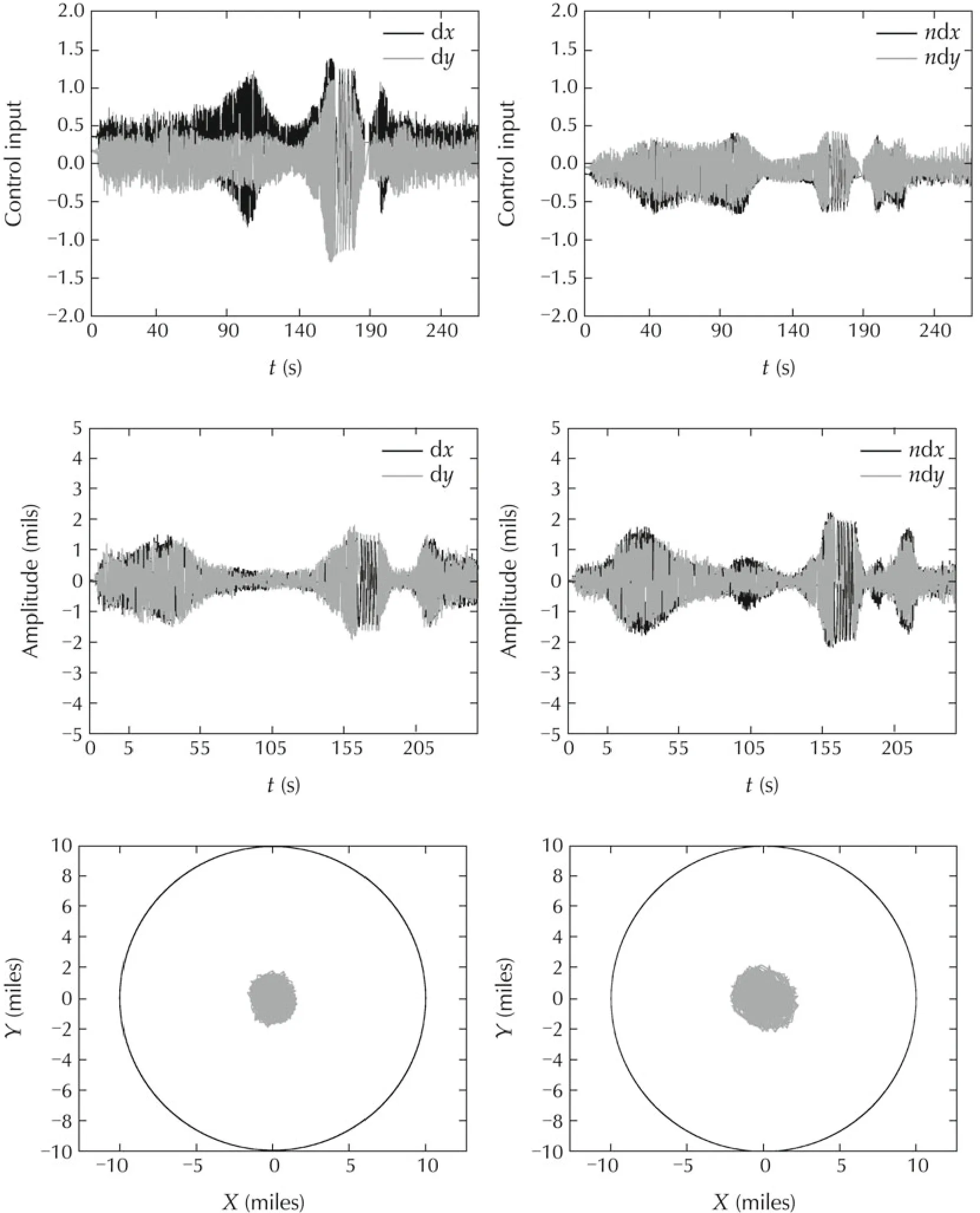
Fig.13 Experimental results with the μ-synthesis controller:control signals,shaft displacements and orbit size.
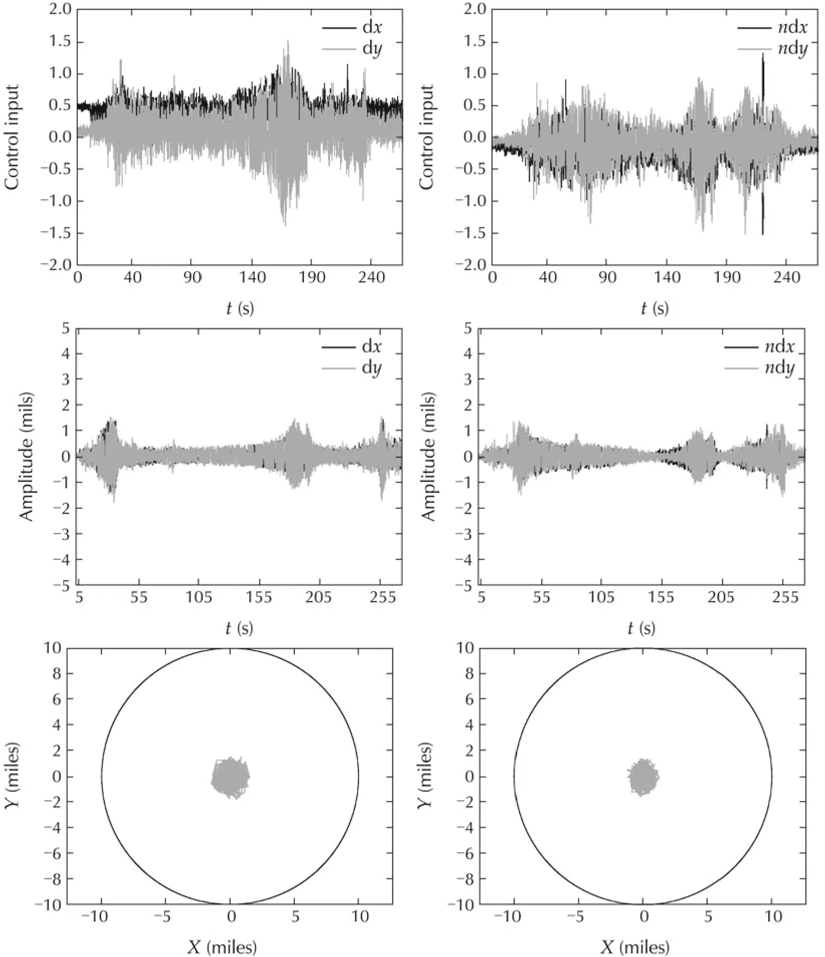
Fig.14 Experimental results with the characteristic model based all-coefficient adaptive controller:control signals,shaft displacements and orbit size.
5 Conclusions
In this paper,we have explored and reported on the application of the characteristic model based all coefficient adaptive control on a flexible rotor AMB system.The nonlinearity,uncertainty and high model order of flexible rotor AMB systems cause challenges for controller designs.Although μ-synthesis has been shown to be able to sufficiently handle these challenges, it requiresthe plant and uncertainty models, which are usually nontrivial to obtain.Moreover,even with plant and uncertainty model,the design of the μ-synthesis controller is a rather complex process.The characteristic model based all-coefficient adaptive controller is of low order and simple structure.On the other hand,both simulation and experimental results indicated that,despite its simplicity,the characteristic model based all-coefficient adaptive control is able to provide control performance comparable to what a benchmark μ-synthesis controller can provide,thus demonstrating its strong potential for application in the AMB control systems.
[1]G.Schweitzer,E.H.Maslen.Magnetic Bearings.Berlin:Springer-Verlag,2009.
[2]E.H.Maslen,J.T.Sawicki.μ-synthesis for magnetic bearings:why use such a complicated tool?Proceedings of the ASME International Mechanical Enginering Congress and Exposition:Mechanical Systems and Control.Seattle:ASME,2007:1103–1112.
[3]S.E.Mushi,Z.Lin,P.E.Allaire.Design,construction,and modeling of a flexible rotor active magnetic bearing test rig.IEEEASME Transactions on Mechatronics,2011,17(6):1170–1182.
[4]H.Wu,Z.Sha.An all-coefficient adaptive control method.Acta Automatica Sinica,1985,11(1):12–20.
[5]H.Wu,J.Hu,Y.Xie.Characteristic model-based all-coefficient adaptive control method and its applications.IEEE Transactions on Systems,Man,and Cybernetics–Part C:Applications and Reviews,2007,37(2):213–221.
[6]G.Zhang,H.Wu.An all-coefficient adaptive control method for a class of nonlinear time-varying systems.Science in China–Series F:Information Sciences,2009,52(10):1730–1738.
[7]Z.Zhang,J.Hu.Stability analysis of a hypersonic vehicle controlled by the characteristic model based adaptive controller.Science in China–Series F:Information Sciences,2012,55(10):2243–2256.
[8]H.Wu,Y.Liu,Z.Liu,et al.Characteristic modeling and the control of flexible structure.Science in China–Series F:Information Sciences,2001,44(4):278–291.
[9]G.Zhang,J.Liu,H.Wu.Adaptive control of large flexible structures using the characteristic modeling technique.Proceedings of theIMACSMulticonferenceonComputational Engineering in Systems Applications.Beijing:Tsinghua University Press,2006.
[10]Z.Li,Z.Wang,J.Li.A hybrid control scheme of adaptive and variable structure for flexible spacecraft.Aerospace Science and Technology,2004,8(5):423–430.
[11]S.E.Mushi.Control of Flexible Rotors Supported by Active Magnetic Bearings.Master’s thesis,Charlottesville,VA:University of Virginia,2008.
[12]S.E.Mushi.Robust Control of Rotordynamic Instability in Rotating Machinery Supported by Active Magnetic Bearings.Ph.D.thesis.Charlottesville,VA:University of Virginia,2012.
[13]H.Wu,J.Hu,Y.Xie.Characteristic Model-Based Intelligent Adaptive Control.Beijing:China Science and Technology Press,2008.
[14]B.Meng,H.Wu,Z.Lin,et al.Characteristic model based control of the x-34 reusable launch vehicle in its climbing phase.Science in China Series F:Information Sciences,52(11):2216–2225,2009.
[15]H.Fujiwara,K.Ebina,K.Ebina,et al.Control of flexible rotors supported by active magnetic bearings.Proceedings of the 8th International Symposium on Magnetic Bearings.Mito,Japan,2002:145–150.
[16]S.E.Mushi,Z.Lin,P.E.Allaire.Design,construction and modeling of a flexible rotor active magnetic bearing test rig.Proceedings of the Asme Turbo Expo.Glasgow,U.K.:ASME,2010.
22 November 2013;revised 21 December 2013;accepted 21 December 2013
DOI10.1007/s11768-014-0184-0
†Corresponding author.
E-mail:zl5y@virginia.edu.

Long DI received his B.S.and M.S.degrees,both in Electrical Engineering,from Utah State University,Logan,UT,in 2009 and 2011,respectively.He is currently working toward his Ph.D.degree at the University of Virginia.His main research interest lies in modeling and control of active magnetic bearings.E-mail:ld4vv@virginia.edu.

Zongli LIN is a professor of Electrical and Computer Engineering at University of Virginia.He received his B.S.degree in Mathematics and Computer Science from Xiamen University,Xiamen,China,in 1983,M.E.degree in Automatic Control from Chinese Academy of Space Technology,Beijing,China,in 1989,and his Ph.D.degree in Electrical and Computer Engineering from Washington State University,Pullman,Washington,in 1994.His current research interests include nonlinear control,robust control,and control applications.He was an associate editor of the IEEE Transactions on Automatic Control(2001–2003),IEEE/ASME Transactions on Mechatronics(2006–2009)and IEEE Control Systems Magazine(2005–2012).He was an elected member of the Board of Governors of the IEEE Control Systems Society(2008–2010)and has served on the operating committees and program committees of several conferences.He currently chairs the IEEE Control Systems Society Technical Committee on Nonlinear Systems and Control and serves on the editorial boards of several journals and book series,including Automatica,Systems&Control Letters,Science China Information Sciences,and Springer/Birkhauser book series Control Engineering.He is a fellow of the Institute of Electrical and Electronics Engineers(IEEE),the International Federation of Automatic Control(IFAC)and the American Association for the Advancement of Science(AAAS).E-mail:zl5y@virginia.edu.
 Control Theory and Technology2014年1期
- Control Theory and Technology的其它文章
- Constrained optimal steady-state control for isolated traffic intersections
- Design of high-speed and low-power finite-word-length PID controllers
- Capture condition for endo-atmospheric interceptors steered by ALCS and ARCS
- Distributed attitude synchronization using backstepping and sliding mode control
- Non-Zenoness of piecewise affine dynamical systems and affine complementarity systems with inputs
- Frequency-domain L2-stability conditions for time-varying linear and nonlinear MIMO systems