Perfect Reconstructable Decimated One-Dimensional Empirical Mode Decomposition Filter Banks
Min-Sung Koh and Esteban Rodriguez-Marek
1. Introduction
Since the one-dimensional empirical mode decomposition (1D-EMD) was introduced in [1], it has been applied and extended into many applications such as seismic signal analysis[2], EEG signal analysis[3], signal denoising[4], and speech enhancement[5]. Although the EMD is well suited for analyzing non-stationary and/or non-linear signals, it has a major drawback in that it generates data expansion, as every decomposition level adds a signal of the same length as the original signal.Decomposition levels in the context of the EMD are denominated intrinsic mode functions (IMFs), which can be thought as the frequency components ordered from high to low frequencies. At each decomposition step, the EMD decomposes the signal into a high-frequency component(i.e. the IMF) and a low-frequency component (i.e. the residual).
The IMF is the result of subtracting the average of two envelopes (upper and lower) from the original signal. These envelopes are determined by connecting the maxima and minima of the signal, respectively. The residual is further decomposed to obtain the next high-frequency components.This operation continues iteratively until either a stopping condition has been met or when the residual is monotonic.The synthesis part of the decomposition, i.e. the reconstruction of the original signal, is achieved simply by adding all IMFs and the residual. Without any further processing, the reconstructed and original signals are identical. Since the EMD decomposes a signal into low and high frequency components at each decomposition step, it can be thought as having a filter bank structure. Flandrin et al. showed in [6] that the EMD indeed acts like a dyadic filter bank. However, unlike wavelet filter banks based on perfectly reconstructable analysis/synthesis filters in a tree structure, the EMD does not include downsampling. In fact,if simple downsampling and upsampling operations are performed in EMD data, perfect reconstruction no longer holds. Hence, incorporating downsampling into the EMD requires a special approach. One technique to overcome the problem is presented in this paper, i.e. we generate downsampled IMFs and a residual while keeping the perfect reconstruction property. The resulting structure is very similar to that of wavelet filter banks, which can be applicable to arbitrary tree structures.
Perfect reconstruction, decimated EMD filter banks are introduced in Section 2 (for analysis filter banks) and Section 3 (for synthesis filter banks). The effect of data reduction of the proposed EMD filter banks is analyzed in Section 4. Experimental results are shown in Section 5 and conclusions follow in Section 6.
2. Analysis EMD Filter Banks
It was shown in [6] that the EMD has a behavior similar to that of a dyadic filter bank. This concept is extended here to allow any arbitrary tree structure to be used with the EMD. To achieve this, we consider only one high-frequency component and one low-frequency component at each decomposition level. In other words, we consider only one IMF and the residual in each decomposition level. Each one of the output signals may be further decomposed into any desired tree structure. At this point, let’s consider the case without downsampling, i.e., still maintaining the perfect reconstruction property. It is clear that forsaking downsampling results in data expansion at each level.However, traditional linear filters that perform the EMD do not exist. Thus, a simple downsampling in an EMD tree structure does not keep the perfect reconstruction property.A special perfect-reconstruction filter set (e.g., perfect reconstructable quadrature mirror filters, or QMFs) is required to achieve perfect reconstruction with downsampling in traditional filter banks. One of these examples is wavelet filter banks. However, if we consider traditional perfect-reconstruction filters (e.g., a QMF) in EMD filter banks, with downsamplers to achieve perfect reconstruction, then the desirable properties of EMD dealing with non-stationary and non-linear signals are limited.
To overcome this problem, this paper takes a different approach, namely, it applies decimation by using“odd”/“even” samples, and the merging operation. Consider the filter structure shown in Fig. 1, displaying one stage of the proposed decomposition. Signal Xi,jis the (i, j)th node of the tree, or the jth node of the ith decomposition level.A length-M signal, Xi,j, can be written as

where R[n] denotes the residual and I [n] denotes the first IMF obtained by the EMD. Note that i=0, 1, 2, …, L and j=0, 1, 2,…, 2L-1, where we are assuming L decomposition levels. Each R[n] and I[n] is split into “even” and “odd”samples, clearly denoted by Re, Ro, Ie, and Io. Note that signal Xi,jcan be either Ieor Refrom a previous level or the original signal. The delay element, denoted by Z-1in Fig. 1,is included when the downsampling process considers only the odd indexed samples. Since the low frequency signals,Roand Re, are very similar to each other, only one low frequency signal, Re, is maintained as the lowpass signal,and defined as Xi+1,2j[m]. This signal may be further decomposed in the next level. Regarding the high frequency signals, Ioand Ie, only the latter is maintained,and is called Xi+1,2j+1[m]. This is the high frequency signal and may also be further decomposed.
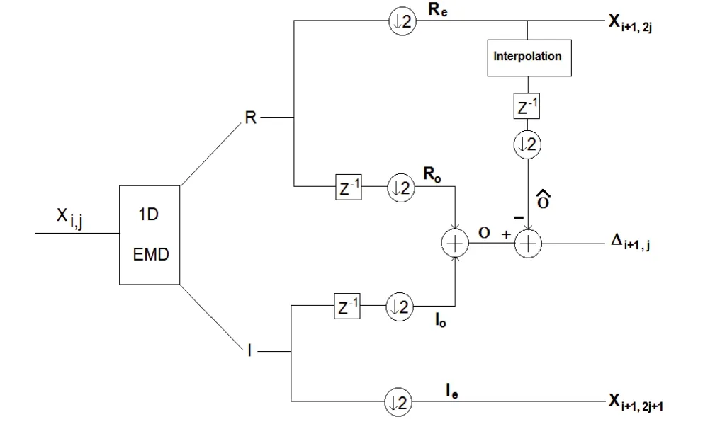
Fig. 1. One stage of the analysis filter bank for the proposed algorithm (at the ith decomposition level).
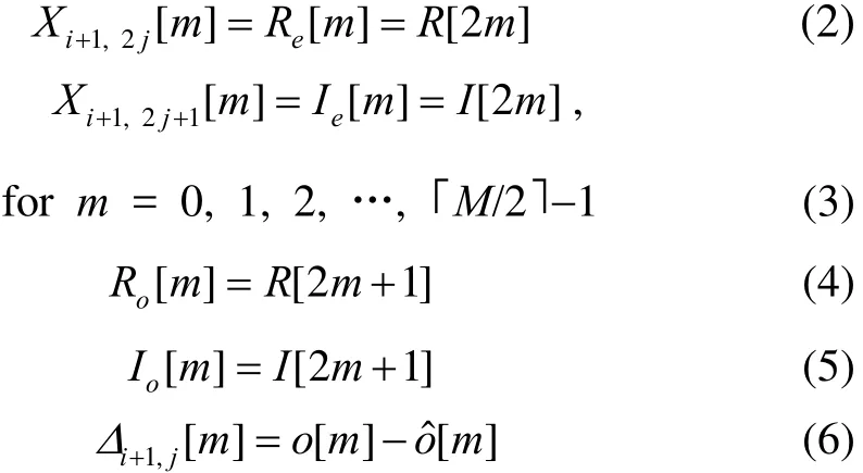
The odd indexed signal, O[m], is the result of the addition of Ro[m] and Io[m]. An error signal, ∆i+1,j[m], is formed from the difference between O[m] and its estimate,Oˆ. This idea is similar to the technique shown in [7] to obtain multiple resolutions of an original image. Note that the estimated odd-indexed signal, Oˆ, is obtained by interpolating Reand taking out the odd-indexed samples.Thus, a single stage of the proposed EMD filter bank generates three outputs, Re, Ie, and ∆, described by for m = 0, 1, 2, …, ⎿M/2」-1, where the input signal is assumed to have length M, and symbol ⎿」 and 「⏋ denote floor and ceiling operations, respectively. Note that if index j is zero or even, then Xi,j[m] implies Re. Otherwise, it implies Ie. Note that while Reand Iecan be further decomposed, ∆ is simply stored to later obtain perfect reconstruction. In addition, all three output signals have length M/2, i.e. half the length of the input signal. Since∆i+1,j[m ] has high frequency components when compared with Re(which has the even-indexed samples of the lowpass residual, R), it is similar to Ie. In other words,∆i+1,j[m ], is similar to Xi+1,2j+1[m]. The similarity between these two signals will be shown in Section 5. Note that if Reand Ieundergo further decomposition, then the length of the decomposed signals keeps getting reduced, i.e. the data length of Xi,j[m] becomes M/2iat the ith decomposition level.
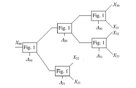
Fig. 2. Octave tree structure with L=3.
If we cascade the same decomposition structure shown in Fig. 1 based on a tree structure, then the proposed algorithm generates a decimated, perfect-reconstruction EMD filter bank similar to traditional wavelet filter banks,as shown in Fig. 2. In Fig. 2, the original length-M signal to be decomposed at the root node is denoted as X00[n].Boxes labeled “Fig. 1” denote the decomposition structure shown in Fig. 1. Note that Reand Iecan be identified by the“j” index in the node subscript. In other words, if j is 0 or even number, then Xi,j[ m ] = Re[ m], (i.e. the lowpass signal). Otherwise, Xi,j[ m ] = Ie[ m], i.e. the highpass signal. Note that the data length of all Reand Iesignals in Fig. 2 (i.e. X22[m] , X23[m] , X30[m] , X31[m ] ,X32[m ] , and X33[m]) is no longer M. This, of course, is a result of all Reand Iesignals being decimated by 2i, where i=0, 1, 2, 3. However, in addition to the decomposition coefficients, we must store the error data represented by ∆.For the example in Fig. 2, the additional data kept are∆10[m ], ∆20[m], ∆21[m], ∆30[m], and ∆31[m], having lengths M/2ifor i=0, 1, 2, 3. For example, ∆30[m] has M/23=M/8 coefficients to be stored, etc. This structure is more efficient than traditional EMD filter banks without decimation, which generates an M-length signal for each decomposed signal. For instan3ce, EMD filter banks without decimations would generate 2M = 8M data for a full binary tree with three decomposition levels. A more detailed discussion on data size will be presented in Section 4.
3. Synthesis EMD Filter Banks
Traditional EMD requires a simple summation of all IMFs and the residual to recover the original signal.Conversely, the proposed algorithm needs a synthesis part to recover both Ioand Rofrom the combined ∆i,j[ m] and to process the decimated signals at each decomposition level. The structure of a single synthesis stage, shown in Fig. 3, is essentially the reverse of the analysis stage.However, a slight modification must be done, as the original signal is simply recovered through the additions.As shown in Fig. 3, to recover the signal at node (i, j),denoted by Xi,j[m], we need to add the even and odd parts of the signal, properly shifted for correct placement. Note that the even indexed signal is simply obtained by E[ m ] = Re[ m] + Ie[ m]. The synthesis filter bank should be made by cascading the structure of Fig. 3 in the same tree used in the analysis. Note that the estimated signal Oˆ must be generated by the same interpolation technique used in the analysis. As the tree advances towards the root node, X00[m], from node Xi,j[m], intermediate nodes(ik, jk) are identified by

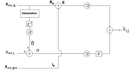
Fig. 3. One stage of the synthesis filter bank at the ith decomposition level.
where i=0, 1, 2, …, L and j=0, 1, 2, …, 2L-1, for L decomposition levels.
Although the EMD behaves like a dyadic filter bank,the exact cutoff frequency is not known, as it is a datadriven decomposition. However, the filter banks shown in Fig. 1 and Fig. 3 provide perfect reconstruction, as well as no aliasing.
Theorem 1. The decimated EMD filter banks in Fig. 1 and Fig. 3 have perfect reconstruction and cancel aliasing,provided the same interpolation technique is used for analysis and synthesis.
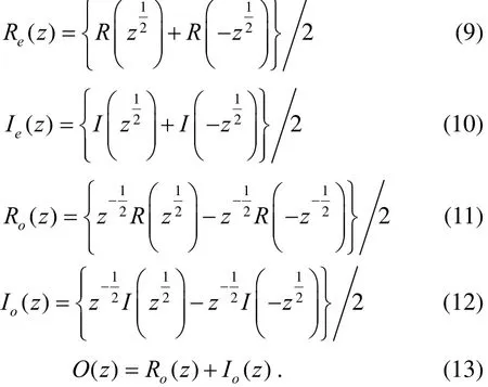
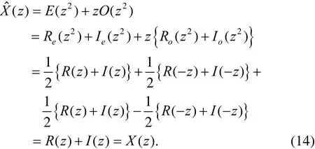
Knowing that E ( z) = Re( z) + Ie(z ), we apply all identities to get
4. Data Reduction Ratio of the Proposed Algorithm
Like wavelet filter banks, the proposed EMD filter bank structure can also be applied into any arbitrary tree structure, including decimation, although with the additional ∆i,j[ m] coefficients. Even after combining Roand Iointo ∆i,j[ m] , the proposed algorithm presents no loss of data, as Roand Iomay be recovered through the interpolation of Reand the addition of ∆i,j[ m]. Hence,perfect reconstruction is guaranteed. Comparing it with wavelet filter banks, the proposed filter banks lead to data being expanded by the size of ∆i,j[ m] for each decomposition level. Considering a full binary tree,2l-1[m]are generated at a decomposition level l,because each R, I pair makes one ∆i,j[ m]. Thus, if we add all size-M /2i[m] data generated at each decomposition level i=0, 1, 2,… , L then. Note that there is no∆i,j[ m ] term for i=0, i.e. the root node. The total number LM/2 of coefficients for all ∆i,j[ m] is the upper bound of additional data needed compared with wavelet filter banks,as we arrive to that value considering all possible decompositions in a full binary tree.
Comparing with traditional EMD, the proposed algorithm reduces the amount of data needed to be stored,as decimation is incorporated. Let's consider a length-M signal. Then traditional EMD generates (L+1)M signals (L IMFs and a residual). If we want to extend the traditional EMD into an arbitrary tree structure, then only one IMF and one residual at each decomposition level can be considered for further decomposition. Therefore, an arbitrary full binary tree with L decomposition levels can generate 2Lpossible nodes. Thus, arbitrary EMD filter banks without decimation results in 2LM coefficients to be stored (each node also has a length-M signal).However, the structure presented in Fig. 1 and Fig. 2 resulting in arbitrary EMD filter banks with decimation yields length-M signals for all possible nodes. Including the additional data for∆i,j[ m ] at each node in each decomposition level, the proposed algorithm generates a total M + LM/2 coefficients for a full binary tree. Thus, the total data generated by the proposed algorithm is significantly less than the 2LM data size of the EMD without decimation. Needless to say,for filter banks not having full tree structures, such as an octave filter bank, the additional data to be stored is less than the upper limit LM/2. Compared to traditional EMD filter banks without decimation, the proposed EMD filter bank has a computational reduction ratio (RR) for L decomposition levels equal to

Forsaking the arbitrary tree structure option in traditional EMD,numerator is the ( 1)L M+ data from traditional,undecimated EMD. The denominator is the data generated from the proposed algorithm, i.e.term is needed from only one ∆i,j[m] at each decomposition level.For instance, for L=5, the reduction ratio is RR≈3, implying that the proposed decimated1D-EMD filter bank needs to store three times less data than traditional1D-EMD. For the same number of decomposition levels, a full binary tree results in RR≈9.1. The RR factor is much higher when applied into 2D-EMD filter banks, as shown in [9].
5. Experimental Results
The system in Fig. 1 was implemented with the 1D-EMD provided in [8], and was applied into arbitrary tree structures. In every case tested, SNRs of over 300 dB were achieved, thereby proving the algorithm yields perfect reconstruction.
Fig. 4 compares decimated and undecimated EMD when applied to speech data. The left column of Fig. 4 (a)corresponds to traditional EMD, i.e. without decimation.The speech frame has 4 IMFs and a residual. All signals have the same length. The rightmost column of Fig. 4 (a)shows the effect of simple decimation after the EMD is performed (it is provided only for comparison purposes).The results of the proposed algorithm are shown in Fig. 4(b). The leftmost column of Fig. 4 (b) shows the signal decomposed by the proposed decimated EMD filter bank,where a tree structure with nodes (1, 1), (2, 1), (3, 1), (4, 1),and (4, 0), i.e. X11[m] through X40[m], respectively.
A visual comparison of the left column of Fig. 4 (b) and right column of Fig. 4 (a) shows that the proposed decimated EMD filter bank has similar results to the downsampled version of the original EMD. This implies that the characteristics of the EMD are not affected by the proposed decimation. The indices of left column of Fig. 4(b) demonstrate that the size of the signals is reduced by half with every decomposition level. The right column of Fig. 4 (b) is the error signal, where each row corresponds to(1, 0), (2, 0), (3, 0), and (4, 0), respectively. In other words,∆10[ m] obtained from X10[m] and X11[m] is on the first row,obtained from X20[m] and X21[m] is on the second row, etc.As mentioned, ∆i,j[ m] is equivalent to the highpass signal for odd-indexed signals. Note that the ∆i,j[ m]s (right column of Fig. 4 (b), are similar to the left column of Fig. 4(b), which are the highpass signals for even-indexed values,Ie.
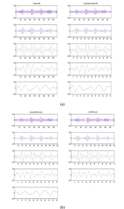
Fig. 4. Comparison of the proposed decimated EMD filter bank with traditional EMD: (a) signals decomposed by the traditional EMD (left column: traditional EMD, right column: downsampled traditional EMD) and (b) signals decomposed by the decimated EMD filter bank (left column: decimated EMD filter bank, right column: ∆ in EMD filter bank).
6. Conclusions
This paper presents an EMD filter bank that allows the generation of any arbitrary tree structure. Moreover, the algorithm allows for perfect reconstruction to be maintained even with the inclusion of decimation. This differs from traditional EMD, which loses the perfectreconstruction capability when downsampled. The obvious benefit from this is the reduction of the amount of data generated by the algorithm. Furthermore, the developed EMD filter banks can be extended into a full binary tree,which results in EMD packets. The proposed EMD filter bank can be applied into any different implementation of traditional 1D-EMD, although only the one reported in [8]is tested in this paper. When the proposed algorithm is applied into 2D-EMD, data reduction is much higher because 2D signals permit row and column decimation.
[1] N.-E. Huang, Z. Shen, S.-R. Long, M.-C. Wu, H.-H. Shih, Q.Zheng, N.-C. Yen, C.-C. Tung, and H.-H. Liu, “The empirical mode decomposition and Hilbert spectrum for nonlinear and non-stationary time series analysis,” Proc. of the Royal Society London A, vol. 454, no. 1971, pp. 903–995,Mar. 1998.
[2] R.-C. Zhang, S. Ma, E. Safak, and S. Hartzell,“Hilbert-Huang transform analysis of dynamic and earthquake motion recordings,” Journal of Engineering Mechanics-ASCE, vol. 129, pp. 861–875, Aug. 2003.
[3] C. Park, D. Looney, P. Kidmose, M. Ungstrup, and D. P.Madic, “Time-frequency analysis of EEG asymmetry using bivariate empirical mode decomposition,” IEEE Trans. on.Neural Systems and Rehab. Eng., vol. 19, no. 4, pp. 366–373,2011.
[4] O. A. Omitaoumu, V. A. Protopopescu, and A. R. Ganguly,“Empirical mode decomposition technique with conditional mutual information for denoising operational sensor data,”IEEE Sensors Journal, vol. 11, no. 10, pp. 2565–2575, 2011.
[5] N. Chatlani and J. J. Soraghan, “EMD-based filtering(EMDF) of low-frequency noise for speech enhancement,”IEEE Trans. on Audio, Speech, and Lang. Proc., vol. 20, no.4, pp. 1158–1166, 2012.
[6] P. Flandrin, G. Rilling, and P. Goncalves, “Empirical mode decomposition as a filter bank,” IEEE Signal Processing Letters, vol. 11, no. 2, pp. 112–114, 2004.
[7] P. J. Burt and E. H. Adelson, “The laplacian pyramid as a compact image code,” IEEE Trans. on Comm., vol. 31, no. 4,pp. 532–540, 1983.
[8] Y. Kopsinis and S. McLaughlin, “Improved EMD using doubly-iterative sifting and high order spline interpolation,”EURASIP Journal on Advances in Signal Processing,doi:10.1155/2008/128293.
[9] M. S. Koh and E. Rodriguez-Marek, “Perfect reconstructable decimated two-dimensional empirical mode decomposition filter banks,” presented at the IEEE Int. Conf.on Acoustics, Speech, and Signal Processing, Vancouver,Canada, 2013.
 Journal of Electronic Science and Technology2014年2期
- Journal of Electronic Science and Technology的其它文章
- Genomic Islands Prediction and Analysis in Cyanobacteira by Bioinfomatics
- Structure Analysis and Classification of Precipitation Cells by Fractal Geometry
- Adaptive Fourier Decomposition Based Time-Frequency Analysis
- Retrieval of High Resolution Satellite Images Using Texture Features
- Call for Papers Journal of Electronic Science and Technology Special Section on Special Section on Energy-Efficient Technologies
- Journal of Electronic Science and Technology Information for Authors
