Simulation of automobile ESP system based on fuzzy control*
Jian OU,Guang-ming LIU,Yi-ting CHEN,E-chuan YANG,Yong ZHANG
1College of Vehicle Engineering,Chongqing University of Technology,Chongqing 400054,China;2Chongqing Dajiang Industry Co.Ltd.,Chongqing 401320,China;3College of Mechanical Engineering,Chongqing University of Technology,Chongqing 400054,China
Simulation of automobile ESP system based on fuzzy control*
Jian OU†1,Guang-ming LIU1,Yi-ting CHEN2,E-chuan YANG3,Yong ZHANG1
1College of Vehicle Engineering,Chongqing University of Technology,Chongqing 400054,China;2Chongqing Dajiang Industry Co.Ltd.,Chongqing 401320,China;3College of Mechanical Engineering,Chongqing University of Technology,Chongqing 400054,China
For enhancing the vehicle hand ling stability,a vehicle dynamics model was established based on the multi-body dynamics analysis software MSC.ADAMS/Car.According to the basic principle of vehicle stability control,the ESP fuzzy control system was designed and the relevant control rules were formulated under the environment of the Matlab/simulink.The vehicle hand ling stability simulation test was carried on under the various typical conditions,using the method of co-simulation.Results show that the designed ESP fuzzy control system can effectively enhance the vehicle handling stability in extreme conditions.
ESP,Co-simulation,Hand ling stability,Fuzzy control
1.Introduction
Automobile active safety technology ESP(Electronic Stability Program)is one of the most mainstream technologies of the automobile industry.It can automatically detect and correct the vehicle instability,to prevent the car skidding or drifting in sharp turns,high-speed lane change,slippery roads and other extreme conditions,and significantly improve the handling stability and driving safety of vehicles[1].However,the car is a typical complex nonlinear system,so it will be very complex to build the mathematical model using MATLAB software,but the mechanical system dynamics analysis package ADAMS/Car can be convenient to construct the whole vehicle model with multi degree of freedom and set typical test conditions,and combined with the abundant data processing function,it is easy to carry out a comprehensive evaluation and analysis on performance of vehicle[2],and adopting the simulink toolbox of MATLAB can be fast and flexible to establish various controller.Based on the merits of the two software,co-simulation contribute to realize the development of vehicle handling stability system design,system performance analysis and evaluation,as well as validation of vehicle handling stability control algorithm[3].
2.The simulation model
2.1.Multi-body vehicle dynamics model
Vehicle modeling based on the ADAMS/Car module uses the modeling method from bottom to top[4].At first the template was built,and then was subsystem,finally a vehicle was assembled.Due to only qualitatively analysis the handling stability of the vehicle in extreme working conditions in this paper,so in addition to brake subsystem direct call steering subsystem,front suspension subsystem,rear suspension subsystem,body subsystem,front wheels and rear wheels subsystem.For the brake subsystem,the original three channel disc brake system is changed into a four channel disc brake system.In the braking system template redefine brake pressure state varia-bles for the two rear wheels:
(mycar.TR_Brake_System.right_rear_brake_ line_pressure)
(mycar.TR_Brake_System.left_rear_brake_line_ pressure)
replacing the original brake pressure state variables,and then save the template.In the standard interface,just save the template generated as a brake subsystem.Finally,the assembly of the subsystem is in the standard interface of ADAMS/Car.The parameters as shown in Table 1.

Table 1.Part parameters of the vehicle mod le
2.2.Two degree of freedom reference model
When not considering the saturation nonlinear characteristics of the tire and ignoring the load change of the wheels,i.e.,tire cornering stiffness is in certain circumstances,there is a linear relationship between side-slip angle and cornering force,at this time,the vehicle model can be seen as a linear model of two degree of freedom.
By the references[5-6]a linear two degrees of freedom differential equations of motion for the car model can be obtained:

Where Yyf,Yyrare respectively the front and rear tire lateral component force along the y-axis direction,βis the vehicle sideslip angle,γis the yaw rate,u is the speed of the car.Since there is a linear relationship between tyre side force and corresponding side-slip angle,and considering the front wheel steering angle δfis small,combined with the tyre side-slip angle and side-slip angle of mass center of the car,get the following differential equation:

Through Laplace transform of Equation(2),a linear transfer function of the reference model can be written as:
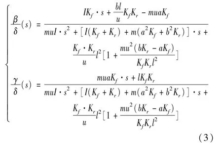
Since most automobile instability occurs in the nonlinear region of cornering characteristics of the tire,namely tire lateral force asymptotic state of saturation,in order to compensate for this instability,the design of ESP control regular need the response regular of two degrees of freedom linear vehicle model as the basis for design.
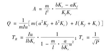
In order to increase the stability of the vehicle,often want to the vehicle side-slip angle response tends to zero,and when the vehicle side-slip angle tends to zero,yaw rate as the first-order lag response of the front wheel angle,so can rewrite the yaw rate response in formula(3).The final formula(3)and respond to front wheel angle can be written as:

Where GR,GB,Te,TB,Q,P are determined by the relevant vehicle parameters:

3.Control method and controller design
In order to improve the handling stability of the vehicle,the sideslip angle and yaw rate should follow the ideal value[7].This paper uses the yaw rate as the control variable to design the controller,which is used to control the brake pipe pressure.Then based on the MATLAB/Stateflow,the logic diagram of the control wheel was established to switch the logic state of wheel needed to brake.We use the front wheel angleδ(defined as left steering is positive)and yaw rate(defined as counter clockwise is positive)differenceΔr=r-rNOjudge to control wheel.In Stateflow the front wheel angle is defined asδ,yaw rate differenceΔr is defined as e,the left front,right front,left rear,right rear wheel are respectively defined as P1,P2,P3,P4,wheel selection rule and logic[8]shown in Table 2 and Figure 1.
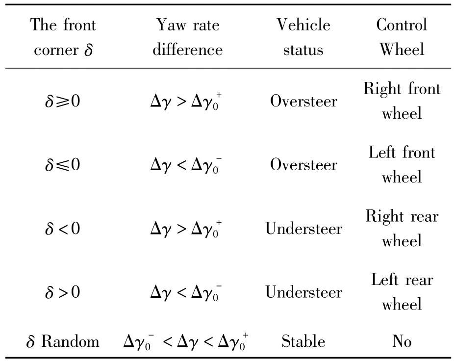
Table 2.Control wheel selection rules
This paper use two-dimensional fuzzy controller to control the yaw rate,the input variables are deviation e and deviation change rate ec between the actual yaw rate and the nominal yaw velocity,the output variable is the brake pressure u.All of their fuzzy subsets are{NB,NS,ZO,PS,PB},respectively represent Negative big,Negative small,Zero,Positive small,Positive big.

Figure 1.Stateflow logic diagram
The principle applied braking force size is when the error is large,the system should make the braking force to eliminate the error as soon as possible,and when the error is small,pay attention to the braking force to prevent overshoot to the stability of the system.Table 3 lists the control rules based on this principle.

Table 3.Control rules table of the yaw ing angular velocity
Fuzzy control using‘Mamdani’approach,reasoning for‘max-min’method,defuzzification method is the area centroid method.The fuzzy controller input and output surface are shown in Figure 2.
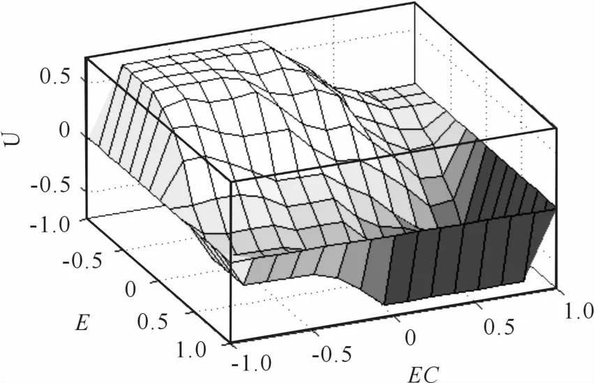
Figure 2.The input and output curve surface of fuzzycontroller
4.Build co-simulation platform
In this paper,the brake pressure is as the ADAMS vehicle model input,the sideslip angle,yaw rate and vehicle steering wheel angle are as output of the vehicle model.Input state variables:
.mycar.TR_Brake_System.left_front_brake_line _pressure
.mycar.TR_Brake_System.right_front_brake_ line_pressure
.mycar.TR_Brake_System.left_rear_brake_line _pressure
.mycar.TR_Brake_System.right_rear_brake_line _pressure
output state variables:
.mycar.testrig.body_side_slip_angle
.mycar.testrig.body_yaw_rate
.mycar.testrig.steering_wheel_angle
Generate S-function of vehicle model in MATLAB,then add the established control systems.Its co-simulation strategy is shown in Figure 3:
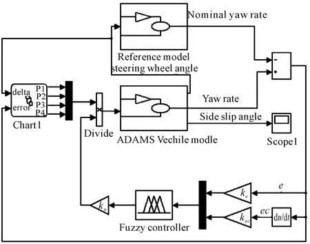
Figure 3.Co-simulation strategy
5.Co-simulation test
According to the research work of ISO(International Standards Organization)TC22/SC9 vehicle handling stability sub-committee,the evaluation methods on vehicle handling stability test generally adopt the following four methods:steady-state response test,the transient response test,lane change test,and pylon course slalom test[9].During cornering or an emergency lane change,the car with a high speed is very easy out of the control of the driver,such as drift,understeer,oversteer,etc.,then the car loses stability and becomes very dangerous,especially on wet roads.Thus,for different vehicle speed and road surface friction coefficient,the paper carried out steering angle step test and single lane change test according to vehicle standard test used to verify the effectiveness of the control algorithm.
5.1.Steering angle step test
The transient characteristics of time domain can be obtained by steering angle step simulation test. Assuming that the driver turns the steering wheel in an emergency at1 s,ending steer at2 s,the steering wheel angle is 100 deg,driver open-loop control.
1)The initial speed is120 km/h,the road surface friction coefficient is 0.8,step steering test,simulation time is 5 s.Test results are shown in Figures 4~8.
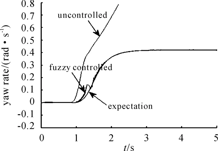
Figure 4.Yaw rate comparison chart

Figure 5.Sideslip angle comparison chart
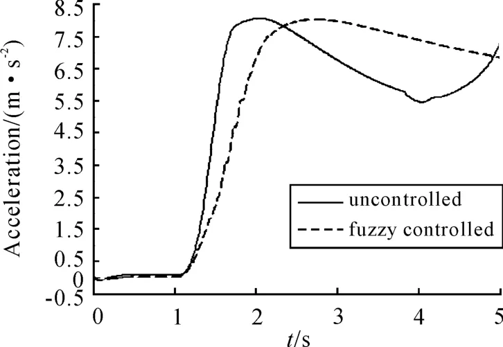
Figure 6.Lateral acceleration comparison chart
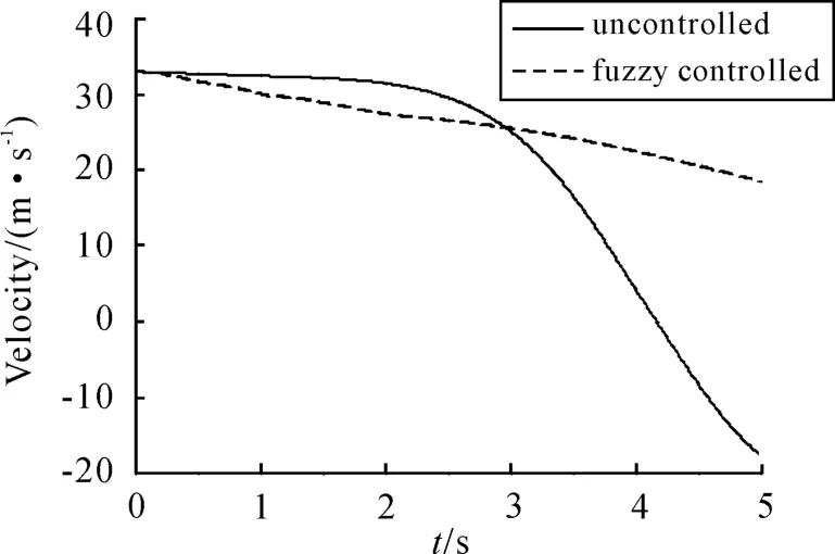
Figure 7.Longitudinal speed comparison chart
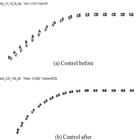
Figure 8.Car trajectory before and after contrast
From the test results,if the driver emergently turn the steering wheel at high speed,even if the road surface friction coefficient is relatively large,the car without installed ESP will appear the wagging tail and even shock rotating dangerous situation,as shown in Figure 8(a),while the car installed ESP is able to adapt suddenly swerved operation and brake the outer front wheel when the car is in oversteer,yaw rate and sideslip angle has a very good response(as shown in Figures 4 and 5),and the speed of the car does not decrease sharply(as shown in Figure 7),the lateral acceleration response is also regular(as shown in Figure 6),the car has an ideal traveling track,as shown in Figure 8(b),the vehicle handling stability is significantly improved.
2)The initial speed is 80 km/h,the road surface friction coefficient is 0.4,step steering test,simulation time is 5 s.Test results are shown in Figures 9~13.
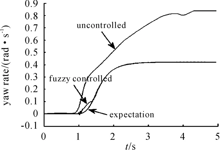
Figure 9.Yaw rate comparison chart

Figure 10.Side slip angle comparison chart
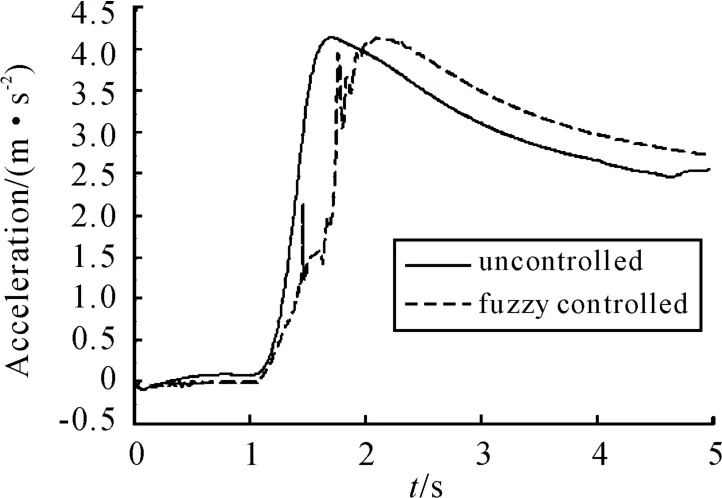
Figure 11.Lateral acceleration comparison chart
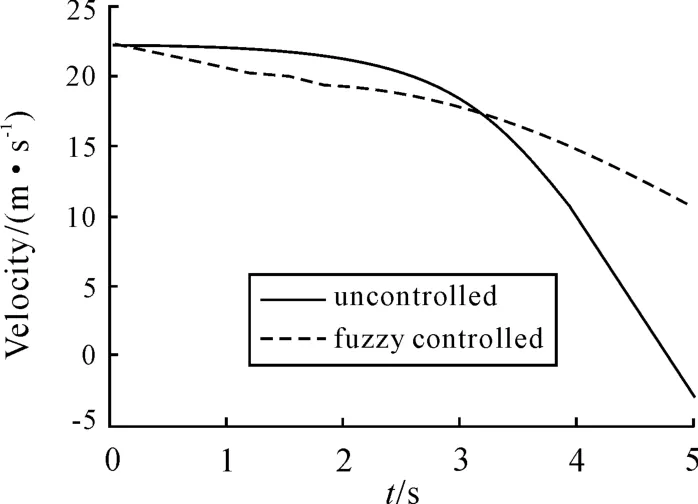
Figure 12.Longitudinal speed comparison chart

Figure 13.Car trajectory before and after contrast
From the test results,at high speed,the driver emergency turn the steering wheel on slippery roads,the car without ESP appears a serious drift phenomenon,lost handling stability,as shown in Figure 13(a).The car installed ESP has a better yaw rate response(as shown in Figure 10)and the sideslip angle has also been a greater control(as shown in Figure 11).Car lateral acceleration and longitudinal speed become more regular,gentle(as shown in Figure 12,13),although the overall effect of vehicle control is quite satisfactory,but due to the low surface friction coefficient,from the trajectory(as shown in Figure 13(b))of the car can be seen also produced some sideslip,so in this case the effect of the control by a single wheel is limited,consider adding auxiliary control wheel to improve control effect.But in general,vehicle handling stability has largely improved after control.
5.2.Single lane change test
Single lane change simulation test refers to drive the car in a specified period of time,to simulate the change action of the car through a S type curve style road.A sinusoidal steering is chosen as the input of steering wheel angle with the beginning at 1s and ending at 3 s,the steering wheel angle is shown in Figure 14:
1)The initial speed is120 km/h,the road surface friction coefficient is 0.8,5-speed gear,single lane change simulation conditions,the simulation time is 5 s,Figures 15~19 show the test results as follows:

Figure 14.Single lane change steering wheel angle input
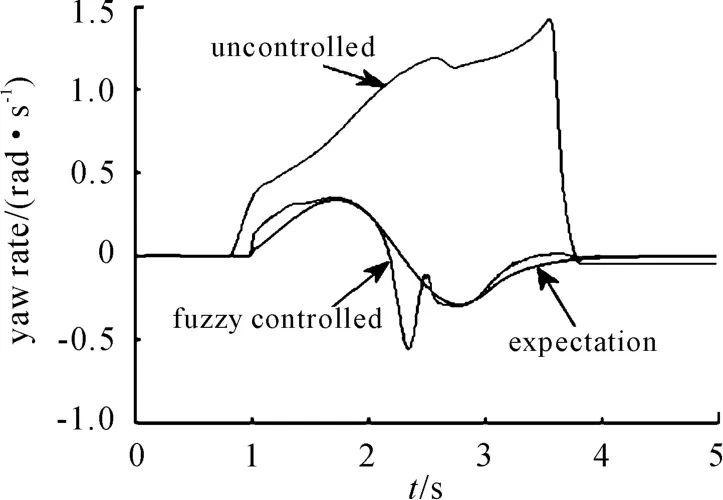
Figure 15.Yaw rate comparison chart
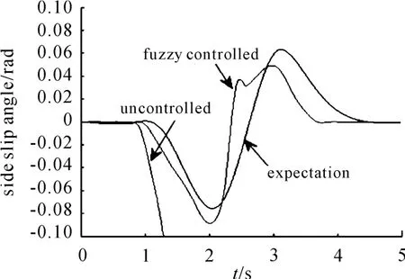
Figure 16.Side slip angle comparison chart

Figure 17.Longitudinal speed comparison chart
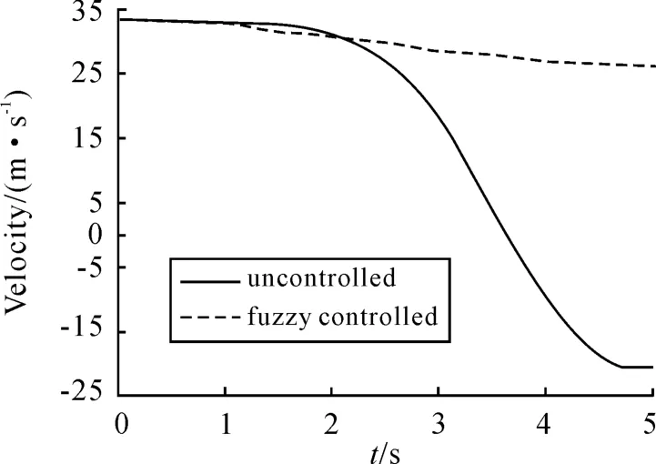
Figure 18.Longitudinal speed comparison chart

Figure 19.Car trajectory before and after contrast
From the test results,in this limit condition,car without ESP appears serious drift phenomenon and can not follow the driver’s willingness to change lanes traveling.The car lost handling stability(as shown in Figure 19(a)).The car installed ESP,its yaw rate and sideslip angle are basically follow the nominal reference values(as shown in Figure 15,16),car lateral acceleration response more regular(as shown in Figure 17),vehicle speed slightly decreases and the change is slow(as shown in Figure 18).The car follows the target track with the intention of the driver,vehicle steering stability has been significantly improved(as shown in Figure 19(b)).
2)The initial speed is 80 km/h,the road surface friction coefficient is 0.4,5-speed gear,single lane change simulation conditions,the simulation time is5 s,the test results are shown in Figures20~24.
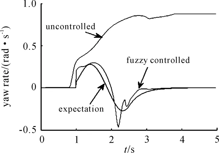
Figure 20.Yaw rate comparison chart
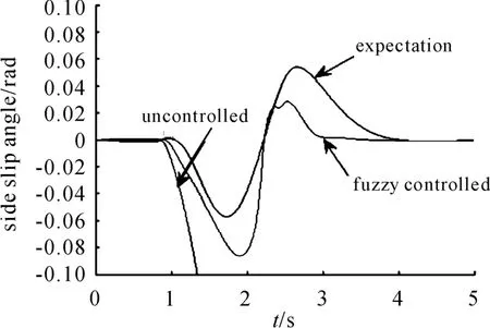
Figure 21.Side slip angle comparison chart

Figure 22.Longitudinal speed comparison chart
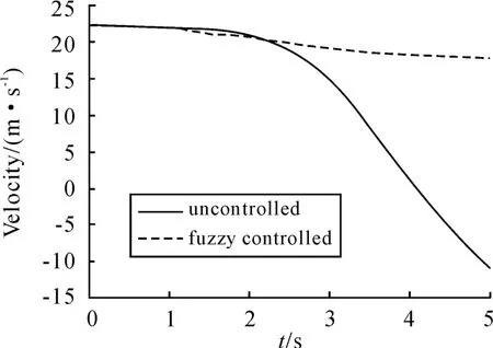
Figure 23.Longitudinal speed comparison chart

Figure 24.Car trajectory before and after contrast
From the test results,in this limit conditions,the car without ESP appears drift phenomenon,lost handling stability.The car installed ESP improved the handling stability than the car without ESP.Due to the lower surface friction coefficient,its sideslip angle is not very ideal(as shown in Figure 21),from its trajectory we can seen the car appears a certain extent side-slip in the process of lane change(as shown in Figure 24(b)),but it can still follow the driver’s intent to change lanes traveling.Overall,the car’s handling stability has been improved.
6.Conclusion
In this paper,taking the vehicle yaw rate as the control variable,a fuzzy controller was built.The effectiveness of this control method was verified through co-simulation between ADAMS/Car and MATLAB. The results show that this control method greatly improves the vehicle handling stability at extreme operating conditions.At the same time by comparing the simulation results,it can be seen that the effect of vehicle control at low road surface friction coefficient is not well as that of high road surface friction coefficient,so the control at low road surface friction coefficient need to be further improved.The future work will be adding auxiliary brake wheel,and considering the tire slip ratio control in order to get better control performance.
[1] Ken Koibuchi,Masaki Yamamoto,Yoshiki Fukada,et al.Vehicle Stability Control in Limit Cornering by active Brake[C].SAE paper,NO.960487.
[2] CHEN Jun.MSC.ADAMS/Car technology and engineering example analysis[M].Beijing:China water conservancy and hydropower press,2008,6-47.
[3] MA Shi-shi,CHEN Jia-qi.Vehicle handling stability of the co-simulation technology research[J].Modern manufacturing engineering,2013,33(4):57-61.
[4] CHEN Li-ping,ZHANG Yun-qing,REN-Wei-qun.Mechanical system dynamics analysis and ADAMS application tutorial[M].Beijing:Tsinghua University Press,2005.
[5] YU Zhi-sheng.Automobile theory(second edition)[M].Bejing:Mechinial Industry Press,2000.
[6] Mitschke M.Vechile dynamics[M].Beijing:China Communication Press,1997.
[7] Abe M,Kano Y,Suzuki K,et al.Side-slip control to stabilize vehicle lateral motion by direct yaw control[J]. JSAE Review,2001(22):413-419.
[8] OU Jian,WANG Lin-feng,FANG Zhan-peng.Automotive electronic stability program fuzzy control simulation[J].Computer simulation.2010,27(7):288-291.
[9] QC/T480—1999 National standard of the People’s Republic of China[S].The vehicle handling stability limit and evaluation method.
基于模糊控制的汽车ESP系统仿真*
欧 健†1,刘广明1,陈毅挺2,杨鄂川3,张 勇1
1.重庆理工大学车辆工程学院,重庆 400054
2.重庆大江工业有限责任公司,重庆 401320
3.重庆理工大学机械工程学院,重庆400054
为提高汽车的操纵稳定性,基于多体动力学分析软件MSC.ADAMS/Car建立了汽车的整车动力学模型。根据汽车稳定性控制的基本原理,在Matlab/simulink环境下建立了ESP模糊控制系统并制定了相应的控制规则。运用联合仿真的方法进行了多种典型工况下汽车操纵稳定性仿真试验。结果表明:所设计的ESP模糊控制系统能有效地提高车辆在极限工况下的操纵稳定性。
ESP;联合仿真;操纵稳定性;模糊控制
U461.6
10.3969/j.issn.1001-3881.2014.18.006
2014-04-22
*Project supported by the Natural Science Fund of Chongqing(CSTS,2008BB6338),2013 Chongqing University Innovation Team Building Program funded projects(KJTD201319),and 2013 Chongqing University of Technology Graduate Innovation Fund(YCX2013203)
†Jian OU,Professor.E-mail:oujian@cqut.edu.cn
- 机床与液压的其它文章
- Electro-mechanical power coup ling system for PHEV with high price-performance ratio*
- Research on multi-axial multi-excitations road simulation test method for AMT actuator*
- Research on the inference of CNC machine fault based on Bayes and FTA
- Design and application of attitude measuring device for DC power output filter circuit
- Design of 20 t forging manipulator clam p rotation hydraulic control system*
- Particle removal by an oscillating bubble in the pipe*

