
Design and studyon variable nozzle mixed-flow turbocharger
2013-11-05 08:00HUANGRuo黄若SHANGWentao尚文涛YUZhiyi余志毅
HUANG Ruo(黄若), SHANG Wen-tao(尚文涛), YU Zhi-yi(余志毅)
(School of Mechanical Engineering,Beijing Institute of Technology,Beijing 100081,China)
Variable nozzle ring turbocharger (VNT)could respond to vehicle engine on transient conditions better and achieve a good match with the engine in the whole range of operating conditions.Mixed-flow turbine could maintain a higher turbine isentropic efficiency and a larger flow capacity than radial-flow turbine at high specific speed and low velocity ratioU/C[1],and it could make good use of the engine's exhaust pulse energy[2].The variable nozzle mixed-flow turbocharger(VN-MT)was expected to inherit the advantages of mixed-flow turbine and could greatly improve the turbine performance.Operating conditions of engines with VN-MT can be adjustable in a certain range,and some problems of vehicle engine will be solved,such as lack of gas when at low speed,black smoke,and excessive speed.
A meanline model for a single-entry mixed-flow turbine was developed for two turbine configurations,nozzleless and nozzled under steady state conditions in Ref.[3].The turbine was developed at Imperial College and the design was based on a commercial nozzleless unit that was modified into a variable geometry single-entry turbine.But the outlet gas on nozzle trailing edge has no axis vector component,i.e.,the geometry configuration between nozzle and rotor is not a true VN-MT.A better configuration of nozzle vane with turbine was developed by Kirtley K R et al.in Ref.[4].
W hile there are many literatures on the turbocharger,the research related to design of the VN-M T was quite little so far.In this paper,we developed a new actuating mechanism which atches the true mixed-flow form.At the same time,the characteristics of designed VN-M T was studied.
1 Nozzle vane structure and drivingmechanism design of VNMT
Three main structures of the variable geometry turbocharger(VGT)applies mixed-flow turbine,including variable throat form,variable tongue section and variable nozzle form.In the variable throat section turbocharger,a variable throat device is placed between the engine exhaust pipe outlet and turbine inlet.So,different flow cross-section can be obtained by changing the opening of the throat under different conditions.When a variable section turbocharger with tongue tray is used,the value of area diameter ratio(A/R)will be changed by swing of a variable tongue-shaped nozzle vane placed on the back of turbine intake cross-section.Compared with VNT,variable throat section turbocharger and variable section turbocharger with tongue tray have simple structure,being controlled automatically.But,they have the disadvantages of large flow loss,limited range of regulation and low efficiency of turbocharger.On the other hand,VNT overcomes aforementioned shortcomings and is predominantly used today.
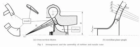
As shown in Fig.1a,the configuration of nozzle vane with turbine might be a true and better option.A spatial motion mechanism[5]has been designed to achieve the nozzle vane rotation according to the form in this paper.According to the parameters,such as chord of nozzle vane,nozzle clearance and cone angle of turbine blade,the curvature of nozzle vane and the volute located upstream of the turbine was designed to make the opening degree of nozzle vane adjusted.Nozzle vane must be placed follow the requirements of spherical shell and the clearance.Corresponding to the impeller blade angle,the nozzle vane was processed into concentric arc-shaped.If the circle center of the nozzle vane is placed on the side of the turbine outlet,the flow line may be able to have a small bending and less fluid loss.But it can not ensure that the curvature radius of the nozzle vane is located on the same circle center.Therefore,each nozzle vane can be rotated by a driving mechanism respectively,which results in the complexity of the manufacturing process and remote feasibility in reality implementation.So this was not considered.
As shown in Fig.1b,the location of the nozzle vanes are placed reasonably.In the meridional plane,the gap between the trailing edge of the nozzle vane and the leading edge of rotor isc.Based on the symmetrical airfoil nozzle vane,the rotation shaft was placed on 1/3chord of the nozzle vane,close to the nozzle ring trailing edge.The axis line of nozzle vane and central axis line of turbine intersection is the centre of sphereO.In order to achieve the nozzle vane rotation between the shroud and hub,the nozzle vane was designed to be arc-shaped on its back and abdomen whose centerOwas located on the back side of the turbine.The arcR1,R2,R3,andR4has the same centerO,and(R2-R1)=(R4-R3)=b,wherebis the nozzle clearance.The method presented in Ref.[6]was used to complete the one dimensional method,generally applied in the design of the volute of radial and mixed flow turbine.Based on the free vortex theory,the continuity equation of fluid and theA/Rvalue under the design condition,the one-dimensional method was used to the mixed-flow volute design.
The driving mechanism consists of actuator,rocker arm component,driving ring and spatial linkage.Its connection form is as follows:actuator and rocker arm component are connected,rocker arm component and spatial linkage are connected,spatial linkage and the shaft of the nozzle vane.Actuator,rocker arm component and driving ring are the same as radial-flow VNT.This mechanism principle is shown in Fig.2.Spatial linkage depends on the form of R-R-S-R-R,where R represents revolute joint and S represents spherical joint.The results showed that the nozzle vane could be rotated freely under the action of driving mechanism by the simulation carried out with kinematic analysis.As shown in Fig.3,within three cycles of rotation process,the displacement of the revolute joint at the nozzle vane is almost 0in all directions.In other words,under the action of driving mechanism,the rotation of the nozzle vane is stabilized.


2 Turbine performance simulation and calculation
Because the flow characteristics of the turbine was determined by the volute section 0-0,the volute based on mixed-flow turbocharger HP50was redesigned only according to equal loop quantity method and continuity equation.In design process,theA/Rvalue is a constant,theAθ/Rθvalue of different rotation angles meet the equationAθ/Rθ=(A/R)0(1-θ/2π),the cross-section area and the corresponding size are determined finally.In the above formula,Arepresents cross-section area;Rrepresents radius from cross-section centroid to turbine-shaft,andAθandRθrepresent cross-section ar-ea and radius from cross-section centroid to turbineshaft under different rotation angle.
Fig.4shows the 3Dmodel built with Pro/E software.There are 12nozzle vanes and 11turbine blades.Fig.5presents the layout of nozzle vanes and turbine blades in the direction of the meridian plane.
Commercial code EURANUS,integrated in Fine/Turbo interface,was used in the numerical simulation.It solves the time dependent Reynolds averaged N-S equations.The equations were discredited using a central difference scheme and a steady state flow solution was achieved upon the convergence of a 4stage explicit Runge-Kutta integration scheme.To speed up the convergence,a full multi-grid technique was applied.The one-equation turbulence model,Spalart-Allmaras model, was used in the present simulation.

2.1 Grid sensitivity study of the turbine stage
The CFD calculation region of the whole turbine stage included volute,impeller and nozzle ring.The mesh of this parts are shown in Fig.6.Multi-block structure mesh of the turbine and nozzle was generated by IGG/AutoGrid automatically.In order to improve the mesh quality,O mesh was used around the nozzle and turbine blade surface block and H mesh was used in the other blocks[7].

The nozzle and blade of impeller have been meshed.The hub gap and shroud gap of nozzle were 0.2mm respectively while the shroud gap of impeller was 0.45mm.The above mesh file have been combined to generate igg file finally.As shown in Tab.1,three different meshes were generated for the volute,nozzle and impeller and grid sensitivity study of the turbine stage was carried out.
With the three different meshes,the predicted performance of the turbine was less than 0.16%.With increased mesh density,the predicted performance would be more accurate but at the expense of more computer resources and simulation time.Calculation results showed that the coarse mesh and medium grid efficiency error was 2.4%while medium grid and fine mesh efficiency error was 0.7%.In present research,the second mesh was used to simulate the overall performance of the turbine stage.The total number of grid was 2 536 845,the minimum orthogonality was 10.9,the maximum aspect ratio was 475.4,and the maximum expansion ratio was 3.2.The grid met the mesh quality requirements of simulation.

Tab.1 Grid sensitivity study of the turbine
2.2 CFD simulation results and analysis
2.2.1 Turbine characteristics analysis
The turbine characteristics was obtained after CFD simulation.The turbine characteristic meant the flow capacity against the pressure ratioπtrelation curve and the efficiency of turbineηagainst the velocity ratioU/Crelation curve was obtained.The former was turbine flow characteristic,and the latter was turbine efficiency characteristic.Some parameters are defined as

whereUis circumferential speed of the inlet(m/s),Cis theoretical speed(m/s),is total pressure of the inlet(Pa),andPT2is static pressure of the outlet(Pa).
As shown in Fig.7,the flow characteristic of the nozzleless turbocharger against with VN-MT in different openings indicated that the flow rate of the nozzleless turbocharger was in middle of VN-MT on different speeds.That is,the VN-MT owned a larger adjustable flow range than the nozzleless mixed-flow turbocharger.So,VN-MT achieved a better match to the engine.Comparing to the large opening(60%)of the nozzle ring,the corrected mass flow of mixed-flow turbine obviously reduced at the small opening(20%).With the engine speed decreased,the mass flow of turbine reduced too.At this very moment,VN-MT could maintain a higher pressure ratio and get a higher boost pressure.

In Fig.7,corrected mass flow is defined asGT(10-5kg·K0.5·s-1·Pa-1),whereGTis turbine mass flow(kg/s)andT﹡Tis total temperature of the turbine inlet(K).
From efficiency characteristic curve in Fig.8,it can be seen that as the nozzle ring opening changed,the efficiency also changed at the same speed(n=4 443 r/min).There was a maximum efficiency at 20%opening of the nozzle ring compared to the others(60%and80%).It was clear that the efficiency declined when the opening of the nozzle ring became large.The efficiency of the nozzleless mixed-flow turbocharger was greater than the efficiency of VN-MT.That was to say,there was more actual enthalpy drop in the nozzleless mixed-flow turbocharger than in the VN-MT at the same expansion ratio.In Fig.8,corrected speed is defined aswherenTis rotor speed(r/min)andT﹡Tis total temperature of the inlet(K).

Fig.8 Efficiency characteristic(the same speed)
From the efficiency characteristic curve in Fig.9,for both the nozzleless mixed-flow turbocharger or the VN-MT,the velocity ratio valueU/Ccorresponding to the maximum efficiency point was between 0.57 and 0.62,which was less than the radial-flow turbocharger’s(the value was 0.7 generally)[8].Compared with the radial-flow turbocharger,the turbine stage load factor[9]of the VN-MT was higher.The lower theU/Cvalue corresponding to the engine torque under low-speed working condition was,the higher the turbine efficiency was.It was beneficial to meet the low speed and high torque requirements of turbocharged engine.

2.2.2 Flow field analysis in turbine stage
The VN-MT received a wider range of flow at the expense of loss of efficiency.Turbine efficiency is closely related to the internal flow characteristics.In order to reduce energy loss of fluid and improve turbine efficiency,flow field in turbine stage was studied.Entropy is the lost parts of energy in the process of energy conversion.It leads to the decline of the system adiabatic efficiency.Entropy produced with fluid flowing was studied in turbine stage.From Fig.10,circumferentially-averaged entropy distribution on the meridional plane was clearly presented.The energy loss in nozzle of VN-MT was smaller than turbine parts.There was a high entropy area near the shroud and hub of turbine blade,especially in hub of the turbine blade compared with nozzleless turbine.This is due to existing friction loss and clearance leakage loss[8]near the shroud while friction loss and separation loss are produced near the hub.

Fig.10 Circumferentially-averaged entropy distribution on the meridional plane
As shown in Fig.11,in VN-MT,limiting streamline near the suction surface varies more gently and air flow organization is better against nozzleless turbocharger.
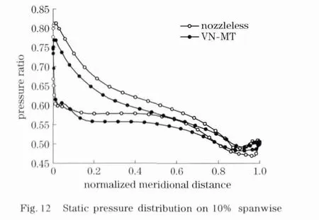
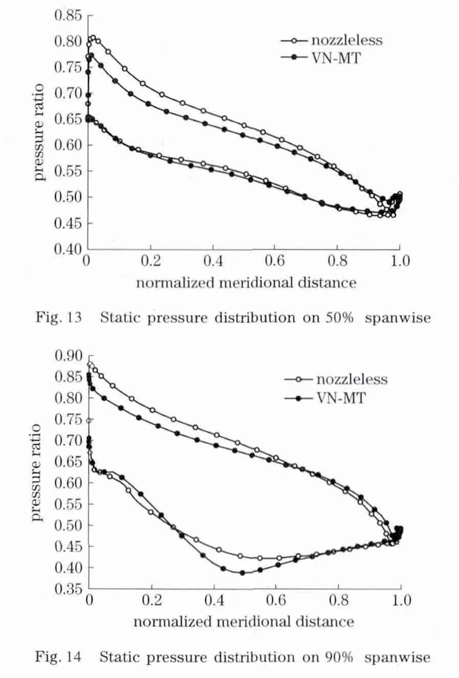
Gas experienced an expansion process in turbine,so the static pressure should reduce from inlet to outlet.In addition,negative pressure area should reduce as possible,especially on suction surface.When the blade load increases to a certain extent,excessive acceleration phenomenon will occur on the suction surface.This will result in existing diffuser regions on throat and outlet.This situation also will appear on pressure surface and suction surface.The greater the degree of expansion pressure was,the higher the possibility of boundary layer separation would be.Boundary layer could be re-attached after separation on pressure surface.But it is different from suction surface.Once boundary layer separation happened on suction surface,boundary layer could not be re-attached.So,energy would lose easily on suction surface and more attention should be paid to the static pressure distribution on it.

Fig.11 Limiting streamline near the suction surface
Fig.12 to Fig.14 present static pressure distribution on respectively(10%,50%and 90%).The static pressure on pressure surface in VN-MT is lower than that in nozzleless turbocharger because of gas expansion in the nozzle ring.At the same time,adverse pressure gradient on suction surface of VN-MT is greater than nozzleless turbocharger.Large boundary layer separation on suction surface of VN-MT leads to energy loss of fluid.The blade load of VN-MT is lower than that of the nozzleless one.So,the peak turbine efficiency point of VN-MT is lower than that of a nozzleless turbocharger.Optimization should be conducted in next research to reduce the loss of fluid separation on suction surface.
3 Conclusion
The nozzle vane could rotate around its axis in different ways with the direction of the turbine shaft,and realized the function of VN-MT by R-RS-R-R spatial mechanism.When the turbine pressure ratio was a constant value,the flow range of VN-MT was wider than that of a nozzleless mixedflow turbine.VN-MT improved the nozzleless mixed-flow turbine performance,and the technology of VN-MT was one of the main internal combustion engine air boost technology in the future.The turbine impeller model in the calculation was the same mixed-flow turbine impeller.The maxi-mum efficiency of nozzleless mixed-flow turbine was 73%while that of VN-MT was 68%at various opening of the nozzle vane,which was mainly due to flow separation on suction surface.
[1] Rohlik H E.Analytical determination of radial inflow turbine geometry for maximum efficiency.NASA-TND-4383[R].Cleveland,United States:NASA Lewis Research Center,1968.
[2] Shi Xin,Ma Chaochen.Design of mixed-flow turbine for automotive turbocharger[J].Journal of Engineering Thermophysics,2002,23(1):35-38.(in Chinese)
[3] Romagnoli A,Martinez-Botas R.Performance prediction of a nozzled and nozzleless mixed-flow turbine in steady conditions[J].International Journal of Mechanical Sciences,2011,53(8):557-574.
[4] Kirtley K R,Beach T A,Rogo C.Aeroloads and secondary flows in a transonic mixed-flow turbine stage[J].Journal of Turbomachinery,1993,115(3):590-601.
[5] Huang Ruo,Shang Wentao.Variable nozzle mixed-flow turbocharger:China Patent,201110102525.2[P].2011-04-22.(in Chinese)
[6] Mohammed H,Mohamed K H,Hichem T C,et al.Design and flow analysis of radial and mixed flow turbine volutes[C]∥International Gas Turbine Institute.Proceedings of the ASME Turbo Expo.New York,U-nited States:American Society of Mechanical Engineers,2008:2329-2338.
[7] Hu Liangjun,Yang Ce,Sun Harold,et al.Numerical analysis of nozzle clearance’s effect on turbine performance[J].Chinese Journal of Mechanical Engineering,2011,24(4):618-625.
[8] Srithar R,Ricardo M B.Mixed flow turbine research:a review [J].Journal of Turbomachinery,2008,130(4):15-26.
[9] Srithar R,Ricardo M B.Variable geometry mixed flow turbine for turbochargers:an experimental study [J].International Journal of Fluid Machinery and Systems,2008,1(1):155-168.
 Journal of Beijing Institute of Technology2013年4期
- Journal of Beijing Institute of Technology的其它文章
- Numerical studyon the shock responses of submunition dropon various mediums
- Design,analysis and control for an antarctic modular manipulator
- Fuzzycontrol method to minimize the needle deflection duringneedle insertion therapy
- Simulation of multiphase boost DC-DC converter with the stable control strategy
- Low spurious noise frequencysynthesis based on a DDS-driven wideband PLL architecture
- Acylation of 3,4-Diaminofurazan