Simulation of multiphase boost DC-DC converter with the stable control strategy
SOOMRO Amir Mahmood, KHAHRO Shahnawaz Farhan, SYED Feroz Shah,LIAO Xiao-zhong(廖晓钟), FARHAN Manzoor
(1.School of Automation,Beijing Institute of Technology,Beijing 100081,China;2.Mehran University of Engineering and Technology,Jamshoro,Sindh,Pakistan)
The three phase system has been employed in electric power generation,transmission and distribution due to the economic benefit.The three phase system has advantages over single phase system,such as better efficiency,the use of less material and higher power density[1].Additionally,constant average power is obtained with respect to time on account of the phase angle differences in the three phase system.The similar merits increase the utilization of three phase boost DC-DC converter.Many engineering applications need high-power DC-DC conversion such as uninterrupted power supplies,distributed generation and transportation.Up to now various isolated DC-DC converter topologies for high power applications have been proposed[1-10]and can be categorized as voltage fed[2-6]and current fed[1,7-10]with certain advantages and disadvantages.In addition,the boost half bridge DC-DC converter has been reported[11-16].This paper presents the multiphase boost DC-DC converter with the stable control strategy.The multiphase boost DC-DC converter can be used in applications where high power and high voltage are required.The control strategy developed for the converter configuration is stable and effective in operation not only for the same but also for the mismatch turn ratios of high frequency transformers.
1 Circuit description
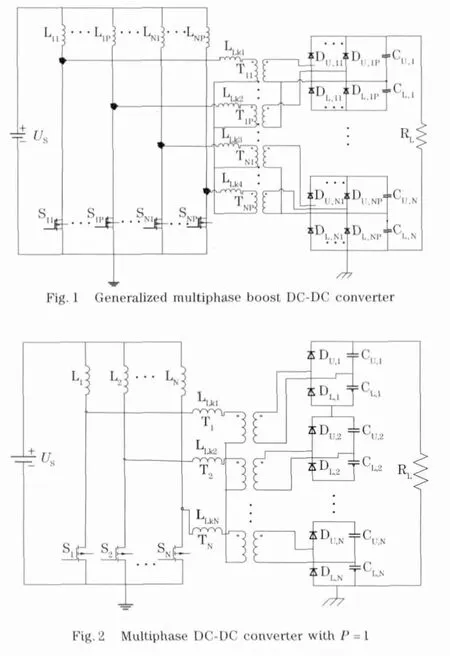
The generalized multiphase boost DC-DC converter is shown in Fig.1.The converter hasNgroups of boost DC-DC converters where each group of switch legs is connected in parallel at the primary side of high frequency transformers.Each group of voltage doublers is connected in series at the secondary side of high frequency transformers.To achieve the high output voltage series configuration of voltage doubler rectifiers,represented byN,have been developed.In the same way,to achieve the high output power parallel configuration of diode legs,denoted asP,have been developed.To acquire high output voltageNwould be enhanced andPwould be increased.The multiphase boost DC-DC converter represented in Fig.2shows an example circuit for increasing the output voltage.As far as the working of the converter is concerned,the duty cycles are generated by PWM for switches through the stable control strategy.

2 Stable control strategy
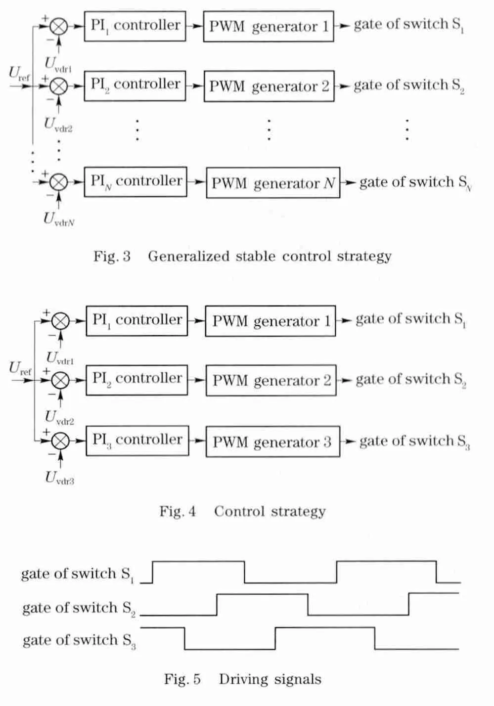
Multiphase boost DC-DC converter consists of generalized stable control strategy which is shown in Fig.3.It is obvious from Fig.3that the generalized stable control strategy needs of N-number of loops in order to have a stable operation for multiphase DC-DC converter.The stable control strategy for simulation of three phase boost DC-DC converter is presented in Fig.4.The working of stable control strategy for three phase boost DC-DC converter can be explained as:a common reference voltage has been set for all the voltage loops and is denoted byUref.This reference voltage has been compared with the voltage at each voltage doubler rectifier that isUvdr1,Uvdr2andUvdr3,respectively.The error signals have been generated after the comparison of reference voltage and individual voltage at each voltage doubler rectifier.These error signals will be given as the input signals for each PI-controller.The signals generated at the output of PI-controllers will be given as an input signals for each PWM generator.The PWM generates the driving signals for switches S1,S2and S3respectively by comparing the output of the PI-controller with high frequency.The driving signals can be termed as duty cycles for switches S1,S2and S3respectively and are shown in Fig.5.The duty cycle can be defined as

whereTonis the turn on time for the switch andTsis the switching time.The range of duty cycle for the stable operation of the control strategy is from 33.33%to 100%.The duty cycle ranging from 0 to 33.33%is prohibited because the input of the converter is current source therefore at least one switch must be ON.

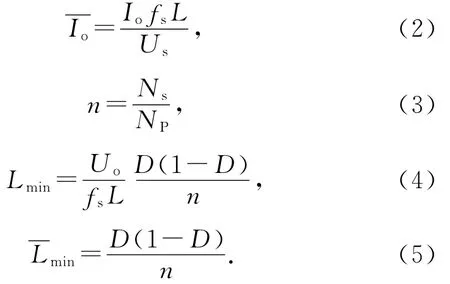
The normalized output current can be calculated by Eq.(2)and the turn ratio of the transformer is shown in Eq.(3).Minimum value of inductances,which are for maintaining the converter operation for a specific condition of load current[17],can be determined by Eqs.(4)(5).

3 Simulation results
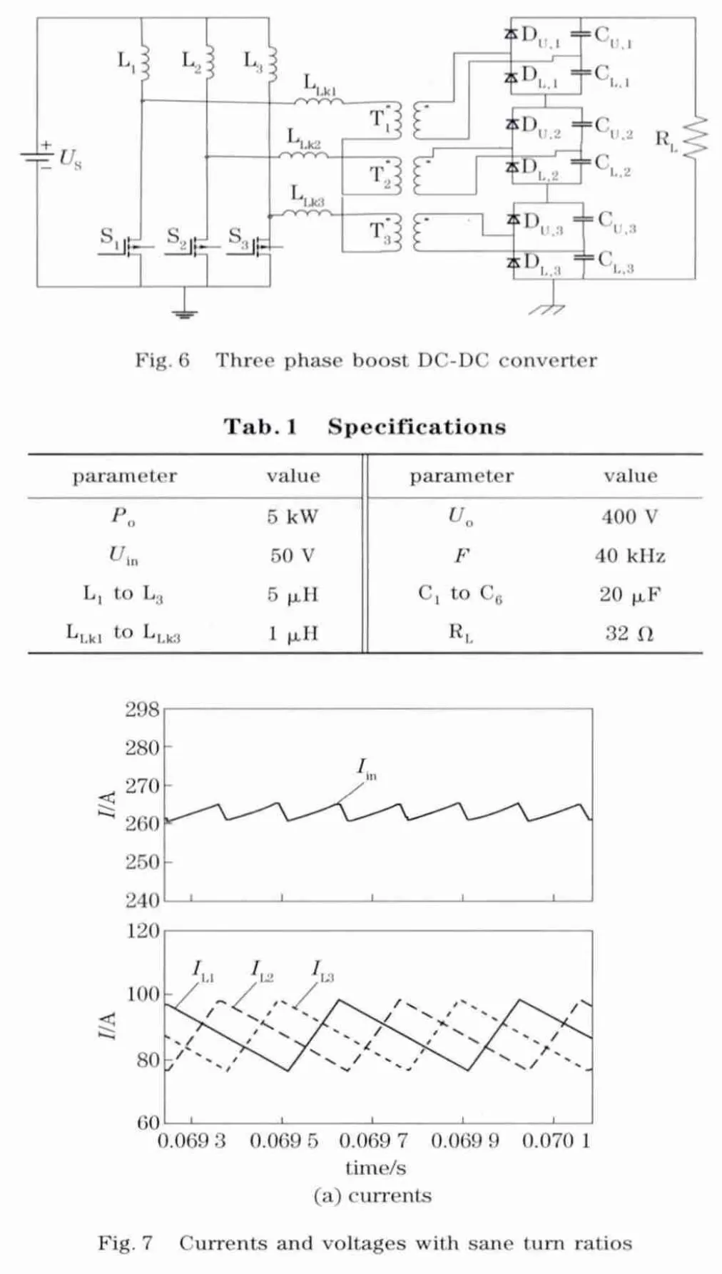
The three phase boost DC-DC converter shown in Fig.6has been simulated along with the stable control strategy represented in Fig.4.For the effective and efficient operation of stable control strategy,three phase boost DC-DC converter has been simulated not only for the same but also for mismatch turn ratios of high frequency transformers.The specifications for the three phase boost DC-DC converter are listed in Tab.1,whereas the value of all leakage inductances are referred to the primary side of high frequency transformers.The simulation has been done for the same and the mismatch turn ratios of high frequency transformers.For the same turn ratios,all the high frequency transformers have been considered as 1∶5.During the simulation of mismatch turn ratios,two of the high frequency transformers are assumed as 1∶5and the third is assumed as 1∶6.The simulation results are shown in Fig.7are for the same turn ratios of high frequency transformer.Fig.7arepresents the total input currentIinand individual phase currentsIL1,IL2andIL3respectively.Fig.7bshows the voltages at each voltage doubler rectifier those areUvdr1,Uvdr2andUvdr3respectively and the output voltageU0.In the same way,Fig.8describes the same parameters for the mismatched turn ratios.


4 Conclusion
The multiphase boost DC-DC converter with the stable control strategy has been presented in this paper.The multiphase boost DC-DC converter along with the series/parallel configuration of the voltage doubler rectifiers could be used for high power and high voltage applications.The design of stable control strategy is as economical and simple as most of the other control strategies proposed for different multiphase DC-DC converters.Although only three phase boost DC-DC converter was simulated here along with the stable control strategy consisting of only three voltage loops,the topology can be modified for the N-number of phases along with the N-number of voltage loops.According to simulation results the main objective of the stable control strategy is achieved,which is the equal power sharing between the input and output of multiphase boost DC-DC converter during the same and the mismatch turn ratios of high frequency transformers.
[1] Andersen R L,Barbi I.A three-phase current-fed pushpull DC-DC converter[J].IEEE Trans Power Electron,2009,24(2):358-368.
[2] Prasad A R,Ziogas P D,Manias S.Analysis and design of a three phase offline DC-DC converter with high-frequency isolation[J].IEEE Trans Ind Appl,1992,28(4):824-832.
[3] Oliveira Jr D S,Barbi I.A three-phase ZVS PWM DC/DC converter with asymmetrical duty cycle for high power applications[J].IEEE Trans Power Electron,2005,20(2):370-377.
[4] Oliveira Jr D S,Barbi I.A three-phase ZVS PWM DC/DC converter with asymmetrical duty cycle associated with a three-phase version of the hybridge rectifier[J].IEEE Trans Power Electron,2005,20(2):354-360.
[5] Kim H,Yoon C,Choi S.A three-phase zero-voltage and zero current switching DC-DC converter for fuel cell applications[J].IEEE Trans Power Electron,2010,25(2):391-398.
[6] Lai J.A high-performance V6converter for fuel cell power conditioning system[C]∥Proc IEEE VPPC 2005.[S.l.]:IEEE,2005:624-630.
[7] Lee S,Choi S.A three-phase current-fed push-pull DCDC converter with active clamp for fuel cell applications[C]∥Proc APEC 2010.[S.l.]:APEC,2010:1934-1941.
[8] Cha H,Choi J,Enjeti P.A three-phase current-fed DC/DC converter with active clamp for low-DC renewable energy sources[J].IEEE Trans Power Electron,2008,23(6):2784-2793.
[9] Oliveira S V G,Barbi I.A three-phase step-up DC-DC converter with a three-phase high frequency transformer[C]∥Proc IEEE ISIE 2005.[S.l.]:IEEE,2005:571-576.
[10] Cha H,Choi J,Han B.A new three-phase interleaved isolated boost converter with active clamp for fuel cells[C]∥Proc IEEE PESC 2008.[S.l.]:IEEE,2008:1271-1276.
[11] Changwoo Yoon,Joongeun Kim,Sewan Choi.Multiphase DC-DC converters using a boost-half-bridge cell for high-voltage and high-power applications[J].IEEE Trans Power Electronic,2011,26(2):381-388.
[12] Fathy K,Lee H,Mishima T,et al.Boost-half bridge single power stage PWM DC-DC converter[C]∥Proc IEEE PECon 2006.[S.l.]:IEEE,2006:426-431.
[13] Zeng J,Ying J,Zhang Q.A novel DC-DC ZVS converter for battery input application[C]∥Proc IEEE APEC 2002.[S.l.]:IEEE,2002:892-896.
[14] Kim C,Moon G,Han S.Voltage doubler rectified boost-integrated half bridge(VDRBHB)converter for digital car audio amplifiers[J].IEEE Trans Power E-lectron,2007,22(6):2321-2330.
[15] Watanabe H,Matsuo H.A novel high-efficient DCDC converter with 1V/20Adc output[C]∥Proc IEEE INTELEC 2002.[S.l.]:IEEE,2002:34-39.
[16] Choi D,Lee B,Choi S,et al.A novel power conversion circuit for cost-effective battery-fuel cell hybrid systems[J].J Power Sour,2005,152:245-255.
[17] Oliveira S V G,Barbi I.A three-phase step-up DC-DC converter with a three-phase high-frequency transformer for DC renewable power source applications[J].IEEE Transactions on Industrial Electronics,2011,58(8):3567-3580.
 Journal of Beijing Institute of Technology2013年4期
- Journal of Beijing Institute of Technology的其它文章
- Numerical simulations of stress wavepropagation and attenuation at arc-shaped interface inlayered SiC/Al composite
- Acylation of 3,4-Diaminofurazan
- Low spurious noise frequencysynthesis based on a DDS-driven wideband PLL architecture
- Fuzzycontrol method to minimize the needle deflection duringneedle insertion therapy
- Design,analysis and control for an antarctic modular manipulator
- Numerical studyon the shock responses of submunition dropon various mediums
