
Development of a dynamic load direct shear apparatus for the study of permafrost
2013-10-09 08:11YingHuiCuiJianKunLiuPengLv
YingHui Cui , JianKun Liu, Peng Lv
School of Civil Engineering, Beijing Jiaotong University, Beijing 100044, China
1 Introduction
The dynamic parameters of permafrost directly affect the accuracy of engineering design and numerical simulation.This paper describes a newly developed dynamic load direct shear apparatus, including its power system and monitoring system, to measure those parameters. Our validation results show that this apparatus and alternative methodology are appropriate for accurately determining the dynamic shear parameters of permafrost.
Compared to frozen soil statics, research on the dynamic aspects of permafrost started later. The dynamic constitutive relations, intensity changes, and dynamic creep properties of frozen soil have been previously studied from different perspectives, including temperature, moisture content, soil texture, confining pressure, loading frequency, and vibration amplitude. Currently, scholars generally test the dynamic properties of permafrost through triaxial tests. For example,Xuet al. (1998) defined the constitutive relations, parameters, and dynamic elasticity modulus of frozen soil based on triaxial tests at low temperature using an MTS-810 vibration triaxial apparatus, which calculated the dynamic Poisson ratio for the first time in China. Wuet al. (2004) also used an MTS-810 apparatus to quantitatively study change laws for the dynamic constitutive model and dynamic elasticity modulus of the deformation of frozen Lanzhou loess at different temperatures (-2 °C, -5 °C, -7 °C, and -10 °C) under seismic loading, which established a correspondence model considering the effects of temperature. Zhaoet al.(2003), using a vibration triaxial apparatus (MTS), conducted a great number of constant stress amplitude experiments under cyclic dynamic loading with confining pressures of 0.3–1.8 MPa at a frequency of 2 Hz. They found that the dynamic strength change of permafrost was not only related to the number of vibrations, but also to the effective energy absorption, confining pressure, and cyclic loading. Zhanget al. (2008), also using the MTS-810 dynamic triaxial testing machine, under the confining pressure of 0.3–1.6 MPa, at a frequency of 2 Hz, -4 and -6 °C temperature conditions,through a series of constant stress amplitude cyclic dynamic load test and found that changes in permafrost dynamic strength with damage not only relate to the size of the vibration times, but also have some relationship with confining pressure and cyclic times.
The advantages of the direct shear apparatus,e.g., simple structure, relatively few required specimens, rapid consoli-dation, time savings, large-instrument stiffness, explicit force transmission, and easy operation, have made it widely used in the world. Compared to the higher cost of a low-temperature vibration triaxial apparatus, the dynamic load direct shear apparatus described here is a lower-cost and more convenient test method which has been readily adopted by engineering and technical personnel and meets project requirements more directly. Moreover, in exceptional cases such as field tests of landslides, shear strength tests of weak planes, contact friction strength tests of some materials,and direct shear experiments, the dynamic load direct shear apparatus may be the only feasible method. This paper reports on the development of a dynamic load direct shear apparatus to test the strength of frozen soil under dynamic loading, and also to test the dynamic friction between different materials.
2 Components of the dynamic load direct shear apparatus
This dynamic load direct shear apparatus, as a complete set of work systems, includes a dynamic loading system, a vertical loading device, a temperature and displacement test apparatus, and a data acquisition system(DAS). The apparatus is able to research the dynamic behaviors of a specimen as well two different kinds of materials influenced by different factors. Its components were designed by the Geotechnical Engineering Lab at Beijing Jiaotong University, and the main frame was built by the Nanjing Soil Instrument Plant. The design included the performance parameters, the design of the dynamic loading system, the direct shear workbench design, and the temperature DAS. The working principle of the apparatus is shown in Figure 1.
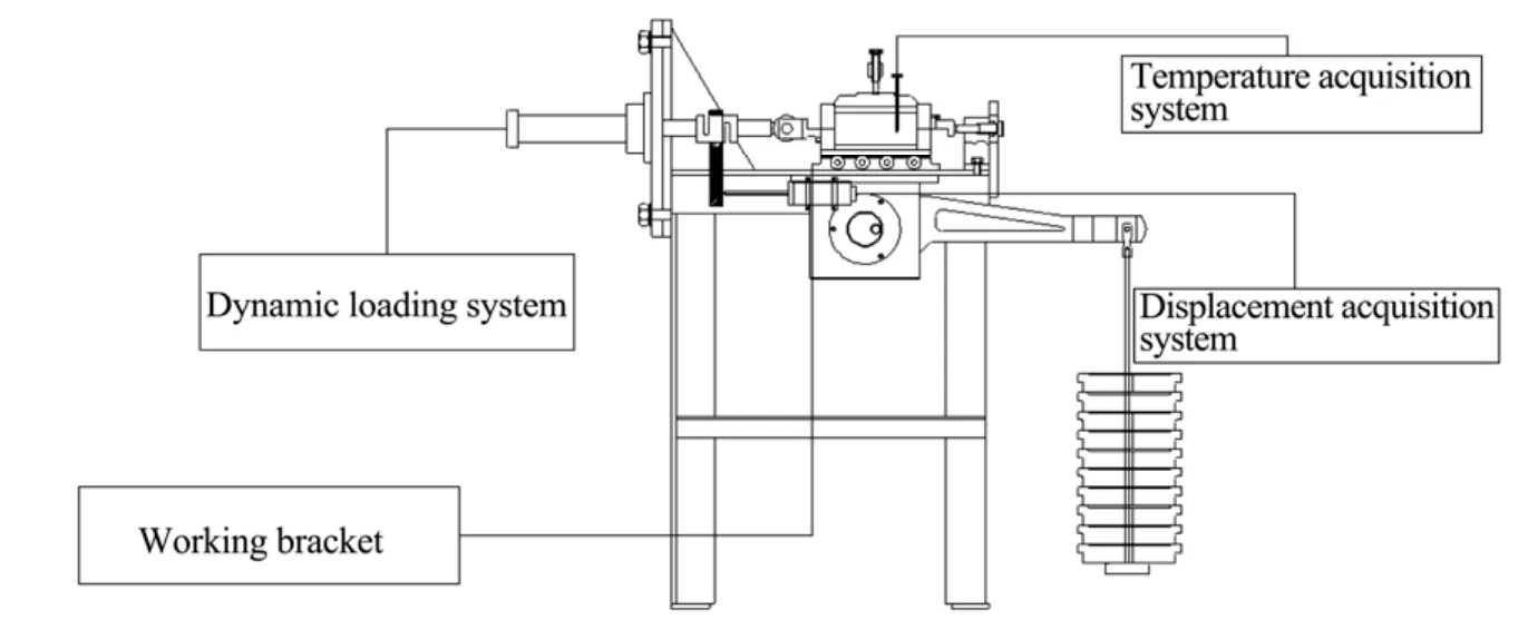
Figure 1 Schematic of the dynamic load direct shear apparatus
3 Actuator design and performance parameters
The dynamic load direct shear apparatus consists of two direct shear boxes. The upper one (150mm×150mm×30mm)is a square hollow tube, and the lower one (150mm×150 mm×30mm) is a square box without a cover, so the shear plane area is 22,500 mm2. The lever structure of the normal force loading device has ratio of 1:24, a maximum load of 9.6 kN, and a normal force of 0–400 kPa.
The dynamic shear strength of soil can be written as:
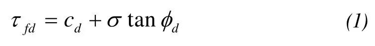
where:τfddenotes the dynamic shear strength of soil;cddenotes the dynamic cohesive force of soil;σdenotes the normal stress of the specimen; andφddenotes the kinetic friction angle of the specimen.
In our study the general axial compression and tension was less than 10.7 kN when the specimen was a failure whose deformation was more than 15% of the specimen’s size, so the telescopic scope of the dynamic loading head was ±22.5 mm.For an ordinary vibration test, the characteristic frequency was 2 Hz. Based on the above values and maintaining allowances for other tests, the dynamic loading system performance parameters are presented in Table 1.

Table 1 Dynamic loading system performance parameters
4 Dynamic loading actuator and direct shear apparatus workbench
The dynamic loading actuator provides power and records the feedback values of the direct shear apparatus in dynamic loading direct shear tests. It was necessary to design the splicing apparatus according to the size of the actuator in order to ensure the stability of the workbench.
The actuator shown in Figure 2 has an axial length of 680 mm, and the shaft of the actuator is 35 mm with a maximum elongation of 200 mm. A square steel plate (400 mm×400mm×20mm) was welded onto the axle body, 340 mm away from the right side of the axle. Holes of diameter φ28 were punched on the corners of the plate and were spaced at 320 mm, and the plate was attached with four screws. Spring gaskets and rubber gaskets were placed at the interface of the screws and nuts to reduce the vibration. A hydraulic pipeline and a control circuit are installed on the rear end of the actuator.
A φ100 hole in the center of the plate enables the telescopic chuck of the actuator to reach the direct shear apparatus workbench. A hinged joint (φ18) in the front of the telescopic chuck is attached to the lower box of the apparatus to confine the lower box’s movement in the axial direction. In these ways the direct shear apparatus is affixed to the actuator, as shown in Figure 2.

Figure 2 Assembly diagram of the actuator and the direct shear apparatus
5 Dynamic loading test measurement system
The instrumented measurement system is mainly composed of a force feedback/stress measurement system, a displacement/strain measurement system, and a temperature measurement system (Liet al., 2012). These three systems can provide automatic data acquisition of stress, strain, and temperature, and then output data files including stress-time,strain-time, and temperature-time in the testing process,which makes it possible to obtain the dynamic physical parameters of the soil specimen.
The force feedback/stress measurement system is affixed to the actuator and consists of a dynamometer and stress sensors. The force value, as collected by computer with an accuracy of 0.02 N, is delivered by the end of the actuator in real time. The sampling frequency of the computer data acquisition can be set; generally, the force feedback/stress and displacement/strain acquisition frequency is set to 50 Hz.
The displacement/strain measurement system is mainly composed of a displacement meter and a DAS. The displacement meter is installed on one side of the direct shear apparatus, and the thimble of the displacement meter sits atop a steel plate affixed to the lower box of the apparatus.Thus, the shear displacement of the lower box can be precisely measured by the displacement meter. In our study the displacement meter was connected to a Donghua DH5956 data acquisition device, enabling the displacement-time data to be seen on the computer monitor.
The temperature DAS consists of a data acquisition instrument and a pt100 thermistor sensor with plug-in joint and an accuracy of 0.1 °C. The pt100 thermistor sensor connector is engraved with scales through which the temperature in the direct shear box can be read out. In our tests,the sensor plug was used to measure the internal temperature of the direct shear box and was generally inserted into the middle of the direct shear box through the opening on the direct shear box cover. In permafrost tests, the internal temperature of soil samples can be monitored in real time.
6 Characteristics of the dynamic loading direct shear apparatus
Compared with a conventional direct shear apparatus,this dynamic load direct shear apparatus has the following characteristics:
1) The dynamic load direct shear apparatus can perform dynamic load tests that an ordinary direct shear apparatus cannot, due to its direct shear apparatus platform and dynamic load actuator components. It is cheaper than a dynamic triaxial apparatus and is easy to operate, and the physical principle of the experimental process is easy to interpret.
2) With the added insulation and the temperature measurement system installed in the direct shear box, the dynamic load direct shear apparatus can conduct permafrost soil sample tests and the soil temperature can be monitored in real time during the tests, which cannot be achieved by a conventional direct shear apparatus in frozen soil tests.
3) The stress and strain measurement system of the dynamic load direct shear apparatus is equipped with automatic data acquisition instruments. Compared to the artificial reading accuracy in a conventional direct shear apparatus,the dynamic load shear apparatus is more accurate because of its high-precision measurement equipment.
7 Verification tests
To test the performance of the direct shear apparatus for dynamic load of frozen soil, we tested the soil comes from subgrade plain fill of Harbin to Shenyang section of the Harbin-Dalian Passenger Dedicated Line. The physical properties of the soil samples are shown in Table 1. In order to test the reliability, we used the standard batch sample preparation methods, that is, made it into 10% water content loose soil before the sample preparation, kept the loose soil under the evaporation limited condition for about 6 hours to evenly, and loaded mode in layers, compacted the soil to the dry bulk density as the test required, then put the soil samples into the -3 °C temperature control box cooling for 48 hours to make sure that different parts of the sample were in the same temperature, met the test requirements. The test procedure was continued for 10 minutes, inserted the thermal sensor in the soil samples during the experimental process, temperature maintained at -3 °C ± 0.2 °C.
The test used the frequency of 1 Hz which is the working condition frequency of typical power system, the vibration waveform used a sine wave, started with the amplitude of 2.5 kN, and increased the interval of 0.1 kN, each stage of loading sustained for 30 seconds, filtered the value fed back by the end of the actuator head sensor and collected by the data acquisition system at the computer end to obtain a dynamic load feedback curve shown in Figure 3, and the horizontal displacement time curves at the same time is shown in Figure 4. Converted the feedback dynamic load value and the horizontal displacement value into stress and strain of the soil samples. We can see that the 28th cycle of stress-strain hysteresis loop as shown in Figure 5 is consistent with the literature, from which the instrument developed in this paper can be validated successfully.
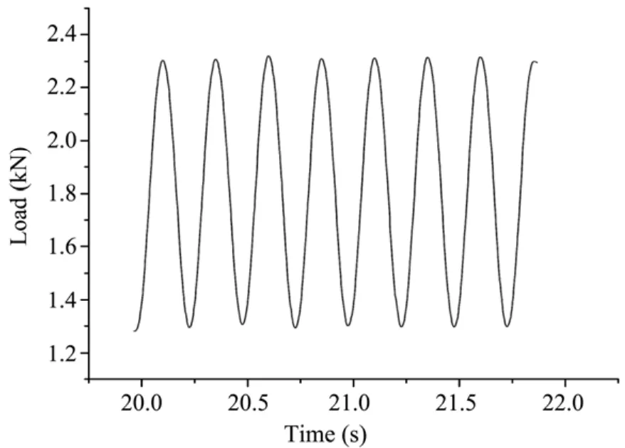
Figure 3 Dynamic load feedback curve

Figure 4 Displacement time curves

Figure 5 Stress–strain hysteresis loop
8 Conclusions
This paper reports on a newly developed dynamic load direct shear apparatus designed for scientific research on permafrost. Compared to a conventional direct shear apparatus, this apparatus provides a new, more accurate method to conduct dynamic shear tests on frozen soil. The structure and working principle of the instrument are described, as is the verification of the performance of the apparatus through a set of experiments. Our results showed that the system can efficiently analyze the dynamic performance of permafrost.Further comparison with traixal test methods will be done in the future.
The authors wish to acknowledge the support provided by the National 973 Project of China (No. 2012CB026104),the National Science Foundation of China (NSFC) (No.41171064), and the Fundamental Research Funds for the Central Universities (No. 2011JBZ009).
Xu XY, Zhong CL, Chen YM, Zhang JY, 1998. Research on dynamic characters of frozen soil and determination of its parameters. Chinese Journal of Geotechnical Engineering, 20(5): 77–82.
Wu ZJ, Zhong CL, Ma W, Cheng JJ, Feng WJ, 2004. Laboratory study on dynamics parameters of frozen soil under seismic dynamic loading.Northwestern Seismological Journal, 25(3): 220–224.
Zhao SP, Zhu YL, He P, Wang DY, 2003. Testing study on dynamic mechanics parameters of frozen soil. Chinese Journal of Rock Mechanics and Engineering, 22(suppl. 2): 2677–2681.
Zhang SJ, Lai YM, Li SY, Chang XX, 2008. Dynamic strength of frozen soils. Chinese Journal of Geotechnical Engineering, 30(4): 595–599.
Li YB, Zhang HR, Quan KJ, 2012. Development of model test system for dynamic frozen soil-pile interaction. Chinese Journal of Geotechnical Engineering, 34(4): 774–780.
 Sciences in Cold and Arid Regions2013年4期
- Sciences in Cold and Arid Regions的其它文章
- Roadbed, embankment, tower support and culvert stability problems on permafrost
- Field monitoring of railroad embankment vibration responses in seasonally frozen regions
- Different discretization method used in coupled water and heat transport mode for soil under freezing conditions
- Reinforcement effects of ground treatment with dynamic compaction replacement in cold and saline soil regions
- Review of the influence of freeze-thaw cycles on the physical and mechanical properties of soil
- Neumann stochastic finite element method for calculating temperature field of frozen soil based on random field theory