
Dynamic constitutive model for soils considering asymmetry of skeleton curve
2013-07-10 12:23:42GuoxingChenHuPnHuiLongXiojunLi
GuoxingChen,HuPn,HuiLong,XiojunLi,c
aInstituteofGeotechnicalEngineering,NanjingUniversityofTechnology,Nanjing210009,China
bGeotechnicalResearchInstitute,HohaiUniversity,Nanjing210098,China
cInstituteofGeophysics,ChinaEarthquakeAdministration,Beijing100081,China
Dynamic constitutive model for soils considering asymmetry of skeleton curve
GuoxingChena,b,HuaPana,∗,HuiLonga,XiaojunLia,c
aInstituteofGeotechnicalEngineering,NanjingUniversityofTechnology,Nanjing210009,China
bGeotechnicalResearchInstitute,HohaiUniversity,Nanjing210098,China
cInstituteofGeophysics,ChinaEarthquakeAdministration,Beijing100081,China
A R T I C L E I N F O
Articlehistory:
Received 18 June 2012
Received in revised form 2 December 2012
Accepted 5 January 2013
Function with double asymptotes
Dynamic constitutive model
Shear modulus
Damping ratio
Complex initial stress state
Based on the asymmetric characteristic of skeleton curve obtained from dynamic tests on soils, a function with double asymptotes is proposed for describing the dynamic constitutive relations of soils. The hysteresis loops observed during unloading and reloading show the same form as the skeleton curve and are constructed by taking the ultimate stress as the corresponding asymptote. The coef ficient of initial unloading modulus is used to ensure that the constructed hysteresis loop fits well with the experimental data. Then, a new dynamic constitutive model considering the asymmetry of skeleton curve is elaborated. The veri fication tests on saturated Nanjing fine sand are performed using a hollow cylinder apparatus to verify the applicability of the UD model. It is found that the predicted curves by the UD model agree well with the test data.
© 2013 Institute of Rock and Soil Mechanics, Chinese Academy of Sciences. Production and hosting by Elsevier B.V. All rights reserved.
1. Introduction
The soil dynamic constitutive model is a basis for studying the dynamic characteristics of soils and soil-structure interaction system under dynamic loads as well as the prerequisite for conducting numerical dynamic analysis.
Masing (1926) suggested a one-dimensional dynamic stress–strain relationship of soil under constant stress cyclic loading. He adopted a hyperbola to describe the skeleton curve, and structured the hysteretic curve using the “double times method”. However, an irrational phenomenon occurred in his model: the value of calculated stress exceeded the ultimate stress under irregular cyclic loading.
Rosenblueth and Herrear (1964) and Newmark and Rosenblueth (1971) respectively put forward the “upper skeleton curve” and“upper large loop” as two supplementary rules to Masing rule. Masing rule and the two supplementary ones were termed as“extended Masing rule”. However, the extended Masing rule cannot be described by a simple mathematical expression. Moreover, it needs tremendous amount of memory capacity to find the intersection point of the present and previous stress–strain curves. Pyke (1979) simplified the extended Masing rule using “ntimes method”instead of “double times method” to restrict the hysteresis loops of follow-up wave within the asymptote of skeleton curve. Besides, Li (1992) modified the Masing rule by introducing the concept of dynamic skeleton curve, which constrains the calculated stress within the ultimate stress.
Wang et al. (1980) made adjustments to the theoretical hysteresis loops by introducing “damping ratio degeneration factor”. This factor led the area of hysteresis loop to fit the experimental value of damping ratio. The essence of this method is to adjust the stress–strain hysteretic damping ratio by changing the original unloading and following shear modulus which is obtained based on the Masing rule. Then, Chen et al. (2009) extended this factor into “general damping ratio degeneration factor” by introducing an adjustment parameterAd. They used a changeable curve to fit the experimental value of damping ratio, thus the fitting can be more flexible.
Based on the studies of Wang et al. (1980), many researchers have conducted extensive studies on this Masing-type constitutive model to analyze the site earthquake responses (Borja et al., 2000; Purzin and Shiran, 2000; Muravskii, 2005; Zhang et al., 2005; Zekkos et al., 2006; Okur and Ansal, 2007; Yamada et al., 2008; Phillips and Hashash, 2009).
The skeleton curves of Masing hysteresis loops can be constructed by hyperbola model (Hardin and Drnevich, 1972a, 1972b), by Ramberg–Osgood model (Ramberg and Osgood, 1943), or by Martin–Davidenkov model (Martin and Seed, 1982). However, in the Martin–Davidenkov model, the shear strain as well as the shearstress may increase infinitely, which is inapplicable to soils. For this reason, Chen and Zhuang (2005) used upper limit value of strain amplitude as a dividing point. The piecewise function was adopted to modify the skeleton curve, and the formula to calculate the damping ratio was deduced. Qi and Bo (2009) put forward a new dynamic constitutive model of soils, in which the exponential function was used to construct the skeleton curve and the hysteresis loop.
As mentioned above, the research results of Masing dynamic constitutive model of soils are quite abundant, whereas there is a fault in common that the skeleton curves adopted are all odd functions which are symmetrical around the origin of coordinates. This does not agree with the results of hysteretic characteristics obtained from the tests under cyclic loading, especially under anisotropic consolidation. In this paper, a function with double asymptotes is proposed for describing the skeleton curves of soils. Then, a new dynamic constitutive model (UD model) considering the asymmetry of skeleton curve is constructed. The verification tests on saturated Nanjing fine sand are performed using a hollow cylinder apparatus to verify the applicability of the UD model.
2. Dynamic constitutive model of soils with asymmetric skeleton curve
2.1.PrinciplesforconstructingMasingtypeconstitutivemodelof soils
The principles for construction of Masing-type constitutive model suitable for soils can be summarized as follows:
(1) During the initial loading, the stress–strain relationship can be described by the skeleton curve.
(2) During the unloading and reloading process, the value of dynamic modulus at the beginning of the unloading process is considered equal to the maximum dynamic shear modulus.
(3) Stress value in the skeleton curve and following hysteresis loop should not exceed the maximum stress level.
(4) The hysteresis loop has the same functional form as the skeleton curve, whereas the parameters are different. The hysteresis loop could be obtained by translating, revolving and scaling the skeleton curve.
2.2.Selectionofskeletoncurvefunction
Considering the principles for constructing dynamic constitutive model of soils, Eq. (1) is adopted to describe the skeleton curve, which has the following features:
(1) The function curve passes through the origin of coordinates.
(2) There are two asymptotes with different absolute asymptotic values.
(3) The function curve becomes convex when the independent variables are positive and concave-down when the independent variables are negative.
(4) The function is continuous and differentiable within its definition domain (− ∞ , + ∞).


Fig. 1. Schematic diagram of skeleton curve.
whereA,t1,t2,kare the fitting parameters, andA< 0,t1< 0,t2< 0,k> 0. The limits of Eq. (1) asxapproaches positive and negative infinity can be respectively expressed as

2.3.Constructionofskeletoncurve
The skeleton curve of the dynamic constitutive model, has the same form as Eq. (1), can be expressed as
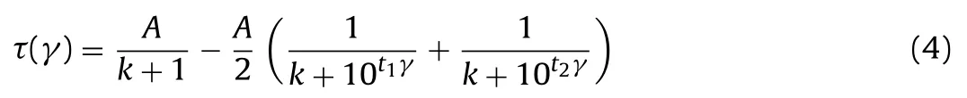
where τ and γ are the dynamic shear stress and dynamic shear strain, respectively. The limits of Eq. (4) can be obtained by
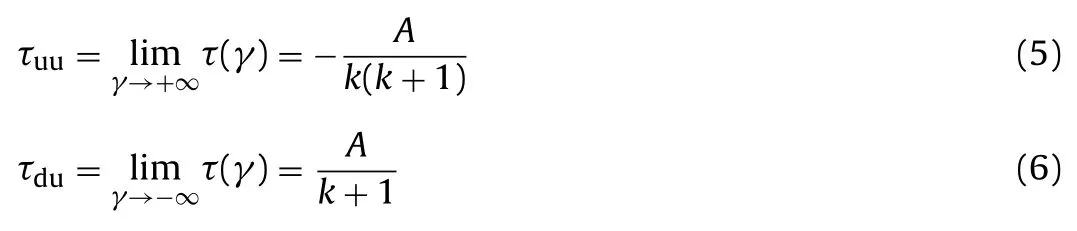
where τuuand τduare the upper and lower asymptotic lines of the skeleton curve, respectively (see Fig. 1).
The value of the maximum initial dynamic shear modulusGmaxcan be obtained from the slope of the tangent through the original pointO(Fig. 1):

From Eqs. (5)–(7), the following equations can be derived:
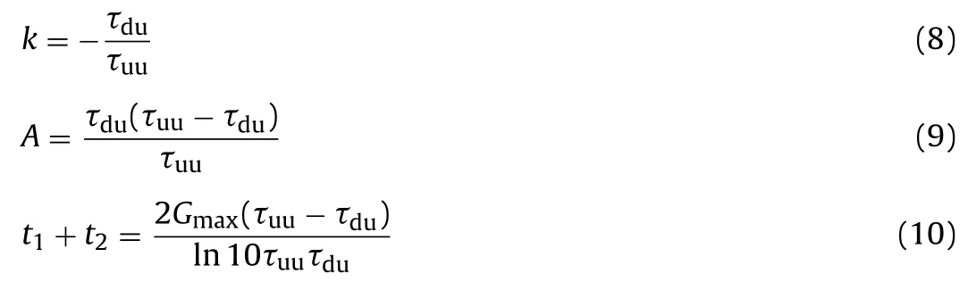
By fitting multiple sets of experimental data, it can be found that, whent1= −100, four parameters of the skeleton curve shown in Eq. (4) can be simplified as three parameters and the fitting results aregood. Thus, the skeleton curve can be determined by
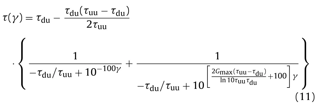
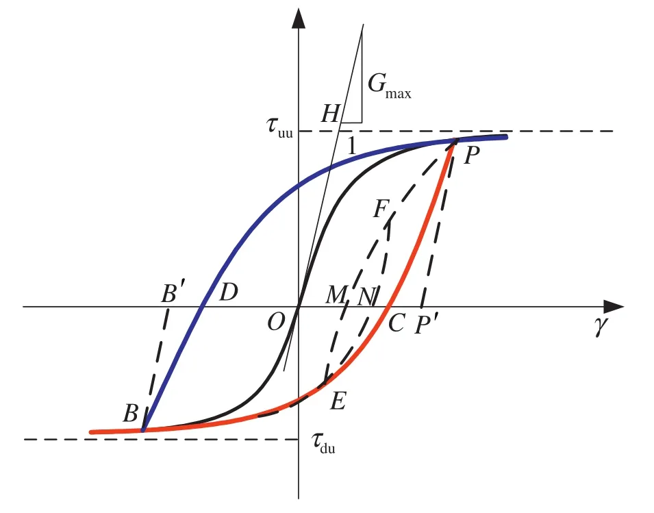
Fig. 2. Schematic diagram of hysteresis loop.
2.4.Constructionofhysteresisloop
Based on the above-mentioned construction principles as well as the processing method from Pyke (1979), the hysteresis loop is constructed by translating and scaling the skeleton curve; meanwhile, τ = τuuand τ = τduare taken as the asymptotes.
2.4.1.Case1:theunloadingpointliesontheskeletoncurve
For this case, first step is to construct the lower hysteresis loop. Set the unloading point (reverse loading point)P(γ0, τP) on the upper skeleton curve, and pointB(− γ0, τB) is the symmetric point ofP(γ0, τP), the value of τBcan be determined by the equations related to the skeleton curve. Then the curvePCBin Fig. 2 corresponds to the lower hysteresis loop, and its functional form is the same as the skeleton curve:
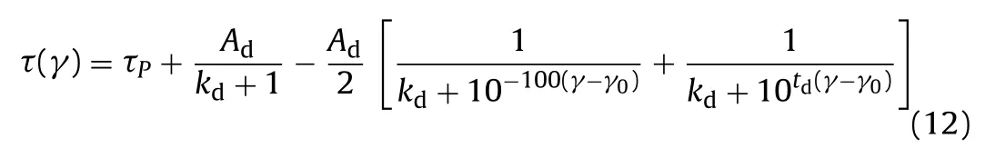
whereAd,kdandtdare the unknown parameters, and the subscript“d” represents the lower hysteresis loop.
In order to determine the value of the three model parameters (Ad,kdandtd), it is assumed that:
(1) The asymptote of the lower hysteresis loop is τ = τdu.
(2) The shear modulus of the initial unloading point on the lower hysteresis loop is equal to the maximum initial shear modulus and can be expressed asPP′‖OHandGP=Gmax.
(3) In order to ensure the closure feature of the hysteresis loop under constant strain cyclic loading, the pointB(− γ0, τB) must be set on the lower hysteresis loop so that the peak point of the hysteresis loop could be on the skeleton curve.
Based on the above assumptions, the following expressions can be obtained:
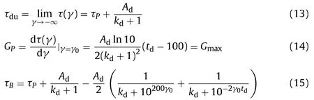
The values ofAd,kdandtdcan be derived from Eqs. (13)–(15), and the expression of the lower hysteresis loop can be determined.
Then the upper hysteresis loop should be constructed. Setting the unloading point (reverse loading point)B(− γ0, τB) on the lower skeleton curve, and the pointP(γ0, τP) is the symmetric point ofB(− γ0, τB). Then the curveBDPin Fig. 2 corresponds to the upper hysteresis loop, and its functional form is the same as the skeleton curve:
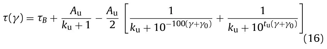
whereAu,kuandtuare the undetermined parameters, and the subscript “u” represents the upper hysteresis loop. Similarly, in order to determine the value of the three model parameters (Au,kuandtu), it is assumed that:
(1) The asymptote of the upper hysteresis loop is τ = τuu.
(2) The shear modulus of initial unloading point on the upper hysteresis loop is equal to the maximum initial shear modulus which is expressed asBB’ ‖OHandGB=Gmax.
(3) In order to ensure the closure feature of the hysteresis loop under constant strain cyclic loading, theP(γ0, τP) must be set on the upper hysteresis loop.
Based on the above assumptions, the following expressions can be obtained:
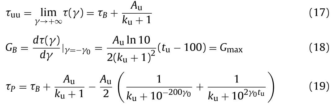
The values ofAu,kuandtucan be obtained from Eqs. (17)–(19), and the expression of the upper hysteresis loop can be determined.
2.4.2.Case2:theunloadingpointisnotontheskeletoncurve
As shown in Fig. 2, it is assumed that the stress–strain process under loading and unloading after the pointPisP→C→E→M→F→N. When analyzing the unloading pointE, the curveEMFis the upper branch of the follow-up hysteresis loop. Its functional form is the same as the skeleton curve. There are three unknown parameters, and three corresponding assumptions need to be made in order to determine the function form of curveEMF. Obviously, the above-mentioned assumptions of the asymptote and taking the shear modulus of the initial unloading point as the maximum initial shear modulusGmaxstill hold true. However, since the pointEis not on the skeleton curve, its corresponding symmetric strain point cannot be determined. Therefore, another assumption needs to be determined.
As a result, it is assumed that if the unloading point is not on the skeleton curve, the following hysteresis loopmust go through the previous unloading point (reverse loading point). Taking pointEwhose previous unloading point is pointPfor example, the curveEMFmust go through the pointP. Therefore, in such a case the unloading point is not on the skeleton curve, the following hysteresis loop can be determined according to the above-mentioned three assumptions.
3. Characteristics of proposed dynamic constitutive model
The proposed dynamic constitutive model, called UD model by authors, has several features as follows:
(1) The function of the skeleton curve has two asymptotes respectively called the upper and lower asymptotes with different absolute asymptotic values, which may re flect that the shear moduli under compression and “tension” are not equal (the“tension” means that the practical soils are not necessarily under tension, whereas the soils must be in tension under loading).
(2) It is suitable for unsymmetrical cyclic loading.
(3) The constructing method is simple and needs little memory consumption, so it is easily accomplished by numerical algorithms.
(4) It has only a few parameters that have clear physical meaning and can be determined by conventional tests.
When verifying the model, it is found that the skeleton curve may fit the test data very well. However, there are two main problems when fitting the test data using the hysteresis loop:
(1) The hysteresis loop constructed by the UD model cannot fit the test date well.

Fig. 3. Verification results of proposed model. (a) Isotropic consolidation (the unloading point is on the skeleton curve). (b) Isotropic consolidation (the unloading point is not on the skeleton curve). (c) Anisotropic consolidation (α0= 0°). (d) Anisotropic consolidation (α0= 45°). (e) Anisotropic consolidation (α0= 90°).
(2) When the strain is comparatively small, the proposed method for determining the hysteresis loop is infeasible: no solution can be obtained by solving the simultaneous equations.
The first problem is commonly understood. It is the same as that in other viscoelastic constitutive models. In order to ensure that the constructed hysteresis loop can well fit the experimental data, additional technological means should be used to adjust the shape of the hysteresis loop, for example using the damping ratio degeneration factor.
With respect to the second problem, it is assumed that the shear modulus of the initial unloading point is equal to the maximum initial shear modulus, which actually is not theoretically founded and is not totally vindicated.
Some results from dynamic tensional shear tests and dynamic triaxial tests (Chen, 2006) demonstrate that the shear modulus of the initial unloading point is not always equal to the maximum initial shear modulus. For normally consolidated cohesive soils or sandy soils, when the strain changes within a small range, the shear modulus of the initial unloading point is usually beyond the maximum initial shear modulus. When the strain varies by a substantial margin, the shear modulus of the initial unloading point is less than the maximum initial shear modulus. The shear modulus of initial unloading point would be in accordance with the maximum initial shear modulus when the strain changes within a medium range. Wang et al. (1980) made adjustments to the theoretical hysteresis loop by introducing a “damping ratio degeneration factor”. The essence of this method is that the adjustment of stress–strain hysteretic damping can be achieved by changing the original and following shear moduli. We found that when the strain changes within a small range, the instantaneous shear modulus can be appropriately raised during the unloading process to solve the above-mentioned second problem. The above two problems can be solved by defining the initial shear modulus coefficient in the unloading process denoted asJ(λ):
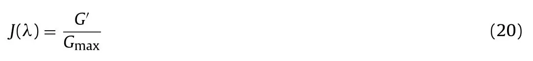
whereG′is the initial shear modulus in unloading process.
It can be found thatJ(λ) would be greater than 1.0 when the strain amplitude of soils is smaller; andJ(λ) would be approximately equal to 1.0 when the strain amplitude of soils is medium; andJ(λ) would be less than 1.0 when the strain amplitude of soils is larger. However, there are no strict standards for the de finition of the dynamic strain amplitude and the distinct boundaries are made among soils with different characteristics which may be determined by a very large number of trials.
Thus, the construction process of the UD model can be described as follows:
(1) According to the above three assumptions (in Case 1 or Case 2), we can solve the simultaneous equations.
(2) If the simultaneous equations have solutions, the corresponding hysteresis loop can be constructed directly; if not, a reasonableJ(λ) can be given in advance on the basis of the value of dynamic strain, and the equation of the hysteresis loop can be constructed.
(3) Make the fitting of damping ratio and adjust the value ofJ(λ) gradually (i.e. adjustG′) till the constructed damping ratio is close to the test result.
4. Model veri fication
To verify the applicability of the proposed model, saturated Nanjing fine sand was employed. Considering different initial consolidation conditions, four sets of further veri fication tests were conducted. Under isotropic consolidation conditions, preliminary examination was made on the hysteresis loop whose unloading point is not on the skeleton curve. Veri fication results of the proposed model are shown in Fig. 3. From Fig. 3, it can be found that the UD model can well predict the stress–strain relationship of the saturated Nanjing fine sand.
5. Conclusions
The asymmetry characteristic of skeleton curve is universal in dynamic testing of soils. However, the existing dynamic constitutive models do not consider the asymmetry characteristics of skeleton curve. A function with double asymptotes can be used to describe the skeleton curve features. Based on this, a new dynamic constitutive model considering the asymmetry of skeleton curve, which is called UD model, is constructed. The coef ficient of initial unloading modulus is used to ensure that the constructed hysteresis loop fits well the experimental data. Four sets of further veri fication tests demonstrate that the UD model can be used to describe the stress–strain relationship of soils under complex stress condition.
Acknowledgements
The authors would like to thank the financial support by the Major Research Plan Integration Project of the National Natural Science Foundation of China under Grant No. 91215301 and by the National Basic Research Program of China under Grant No. 2011CB013601.
Borja RI, Lin CH, Sama KM, Masada GM. Modelling non-linear ground response of non-lique fiable soils. Earthquake Engineering and Structural Dynamics 2000;29(1):63–83.
Chen GX, Zhuang HY. Developed nonlinear dynamic constitutive relations of soils based on Davidenkov skeleton curve. Chinese Journal of Geotechnical Engineering 2005;27(8):860–4 (in Chinese).
Chen XL. Study on soil dynamic characteristics nonlinear seismic response of complex site and its methods. Harbin: Institute of Engineering Mechanics, China Seismological Bureau; 2006 (in Chinese).
Chen XL, Jin X, Tao XX, Li HY. Dynamic constitutive model for soils based on generalized damping degradation coef ficient. Chinese Journal of Computational Mechanics 2009;26(2):245–51 (in Chinese).
Hardin BO, Drnevich VP. Shear modulus and damping in soil: Measurement and parameter effects. Journal of the Soil mechanics and Foundation Engineering Division, ASCE 1972a;98(6):603–24.
Hardin BO, Drnevich VP. Shear modulus and damping in soil: design equations and curves. Journal of the Soil mechanics and Foundation Engineering Division, ASCE 1972b;98(7):667–92.
Li XJ. One simple functional expression of soil dynamic constitutive relations. Chinese Journal of Geotechnical Engineering 1992;14(5):90–4 (in Chinese).
Masing G. Eigenspannungeu und verfertigung beim Messing. In: Proceedings of the 2nd International Congress on Applied Mechanics; 1926. p. 332–5.
Muravskii G. On description of hysteretic behaviour of materials. International Journal of Solids and Structures 2005;42(9/10):2625–44.
Martin PP, Seed HB. One dimensional dynamic ground response analysis. Journal of Geotechnical Engineering, ASCE 1982;108(7):935–52.
Newmark NM, Rosenblueth E. Fundamentals of earthquake engineering. Englewood Cliffs, NJ: Prentice Hall Inc; 1971. p. 163–92.
Okur DV, Ansal A. Stiffness degradation of natural fine grained soils during cyclic loading. Soil Dynamics and Earthquake Engineering 2007;27(9): 843–54.
Purzin AM, Shiran A. Effects of the constitutive relationship on seismic response of soils. Part I. Constitutive modeling of cyclic behavior of soils. Soil Dynamics and Earthquake Engineering 2000;19(5):305–18.
Phillips C, Hashash Y. Damping formulation for nonlinear 1D site response analyses. Soil Dynamics and Earthquake Engineering 2009;29(7):1143–58.
Pyke R. Nonlinear soil models for irregular cyclic loadings. Journal of the Geotechnical Engineering Division, ASCE 1979;105(6):715–25.
Qi WH, Bo JS. A new soil dynamic constitutive model. Earthquake Engineering and Engineering Vibration 2009;29(1):169–74 (in Chinese).
Rosenblueth E, Herrear I. On a kind of hysteretic damping. Journal of the Engineering Mechanics Division, ASCE 1964;90(4):37–47.
Ramberg W, Osgood W. Description of stress strain curves by three parameters. Technical Note No. 902. Washington, DC: National Advisory Committee for Aeronautics; 1943.
Wang ZL, Wang YQ, Han QY. Visco-elastoplastic soil model for irregular shear cyclic dynamic loadings. Chinese Journal of Geotechnical Engineering 1980;2(3):10–20 (in Chinese).
Yamada S, Hyodo M, Orense R, Dinesh S, Hyodo T. Strain-dependent dynamic properties of remolded sand-clay mixtures. Journal of Geotechnical and Geoenvironmental Engineering 2008;134(7):972–81.
Zekkos D, Bray JD, Riemer MF. Shear modulus and material damping of municipal solid waste based on large-scale cyclic triaxial testing. Canadian Geotechnical Journal 2006;45(1):45–58.
Zhang J, Andrus RD, Juang CH. Normalized shear modulus and material damping ratio relationships. Journal of Geotechnical and Geoenvironmental Engineering 2005;131(4):453–60.

Guoxing Chenobtained his M.Sc. and a Ph.D. degree from Institute of Engineering Mechanics, China Earthquake Administration. He is a professor of Civil Engineering and the Dean of College of Transportation Science and Engineering, Nanjing University of Technology. He has been involved in geotechnical and earthquake engineering research, consulting and education more than 20 years. His research fields involve soil dynamics, nonlinear seismic site effects, cyclic triaxial test and shaking table model test technology, rail rapid transit dynamics, as well as earthquake disaster prevention and mitigation of urban underground structure, earth and rock dam. He is the author or co-author of more than 200 scientific papers and he serves on the editorial boards of several top journals in China. He has obtained the professional qualifications of Civil Engineer (Geotechnical) and Level 1 Seismic Hazard Assessment Engineer in China. He is a member of National Seismic Hazard Assessment Committee and Science & Technology Committee of Earthquake Administration in Jiangsu Province. He has consulted widely and has given both geotechnical and seismic advice on a series of major projects. He has been awarded the State-class Young and Middle-aged Experts with Outstanding Contribution in 1996. Also, he has been awarded National Outstanding Scientific and Technological Workers in 2012.
pan1983@163.com (H. Pan).
Peer review under responsibility of Institute of Rock and Soil Mechanics, Chinese Academy of Sciences.
∗Corresponding author. Tel.: +86 15026555734.
E-mail address: hua
1674-7755 © 2013 Institute of Rock and Soil Mechanics, Chinese Academy of Sciences. Production and hosting by Elsevier B.V. All rights reserved.
http://dx.doi.org/10.1016/j.jrmge.2013.01.003
 Journal of Rock Mechanics and Geotechnical Engineering2013年5期
- Journal of Rock Mechanics and Geotechnical Engineering的其它文章
- Easy profit maximization method for open-pit mining
- A discontinuum-based model to simulate compressive and tensile failure in sedimentary rock
- Landslide disaster prevention and mitigation through works in Hong Kong
- Easy profit maximization method for open-pit mining
- Reply to Discussion on “A generalized three-dimensional failure criterion for rock masses”
- Discussion on “A generalized three-dimensional failure criterion for rock masses”