
Treatment design of geological defects in dam foundation of Jinping I hydropower station
2013-07-10 12:23:42ShengwuSongXueminFengHonglingRaoHanhuaiZheng
Shengwu Song, Xuemin Feng, Hongling Rao, Hanhuai Zheng
ChengduHydroelectricInvestigationandDesignInstitute,ChinaHydropowerEngineeringConsultingGroupCorporation,Chengdu610072,China
Treatment design of geological defects in dam foundation of Jinping I hydropower station
Shengwu Song∗, Xuemin Feng, Hongling Rao, Hanhuai Zheng
ChengduHydroelectricInvestigationandDesignInstitute,ChinaHydropowerEngineeringConsultingGroupCorporation,Chengdu610072,China
A R T I C L E I N F O
Articlehistory:
Received 4 March 2013
Received in revised form 24 May 2013
Accepted 18 June 2013
Geological defects
Treatment design
Concrete cushion
Concrete replacement grids
Consolidation grouting
Performance evaluation
Jinping I hydropower station
Jinping I hydropower station is one of the most challenging projects in China due to its highest arch dam and complex geological conditions for construction. After geological investigation into the dam foundation, a few large-scale weak discontinuities are observed. The rock masses in the left dam foundation are intensively unloaded, approximately to the depth of 150–300 m. These serious geological defects lead to a geological asymmetry on the left and right banks, and thus some major difficulties of dam construction are encountered. In this paper, the influences of geological defects on the project are analyzed, followed by the concepts and methods of treatment design. Based on the analysis, the treatment methods of the weak rock masses and discontinuities are carefully determined, including the concrete cushion, concrete replacement grids, and consolidation grouting. They work together to enhance the strength and integrity of the dam foundation. Evaluations and calibrations through geo-mechanical model tests in combination with field monitoring results in early impoundment period show that the arch dam and its foundation are roughly stable, suggesting that the treatment designs are reasonable and effective. The proposed treatment methods and concepts in the context can be helpful for similar complex rock projects.
© 2013 Institute of Rock and Soil Mechanics, Chinese Academy of Sciences. Production and hosting by Elsevier B.V. All rights reserved.
1. Introduction
Jinping I hydropower station is located in Liangshan Yi Autonomous Prefecture, Sichuan Province in Southwest China. It is built on the Yalong River as a controlling cascade hydropower station in the middle and lower reaches, with power generation as its major function. It has annual regulating capacity of water resources and provides remarkable compensation benefits for the lower cascade hydropower stations. The total reservoir capacity is 7.76 × 10⁹m3at a normal water level of 1880 m, and the installed capacity is 3600 MW. The height of concrete double-curvature arch dam is 305 m with the bottom foundation elevation of 1580 m and dam crest elevation of 1885 m, which is the highest under construction in the world.
The hydropower station is built in the transitional slope zone between Qinghai-Tibet Plateau and Sichuan Basin. In the project area, the river valley is sharply incised with high steep slopes on both banks. Large-scale tectonic faults with strikes of river direction are developed and rock masses in left bank are intensively unloaded with depth of 150–300 m (Liu et al., 2010; Song et al., 2011), leading to a geological asymmetry on the left and right banks. For these geological defects existing, the rock mass quality in the studied area basically cannot meet the requirements of the dam foundation construction. Consequently, the arch dam project is regarded as one of the most challenging projects with complex geological conditions and difficult foundation treatments (Liu et al., 2004; Fan et al., 2012).
The design of Jinping I hydropower station was completed in 2003. After the excavation of dam foundation, the subsequent concrete placing of the dam started in 2009. At the end of 2012, the diversion tunnels were plugged and early impoundment of the reservoir began. At present, the concrete arch dam is constructed up to a height of 280 m, and most of the foundation treatments have been implemented. According to the schedule, the dam will be impounded and put into power generation in August 2013. In this paper, the analytical methods, design concepts, treatment measures and technical features of strengthening the geological defects in the dam foundation will be presented.
2. Geological settings of dam foundation
In the project region, the Yalong River flows along the direction of N25°E, with water level of 1635 m in dry season. The top elevation of the valley mountains reaches up to 3200–3600 m, andrelative height difference of topography is 1500–2000 m. High and steep slopes stand in precipitous gorges and V-shaped valleys are sharplyincised,withadeclinationof40°–90°.
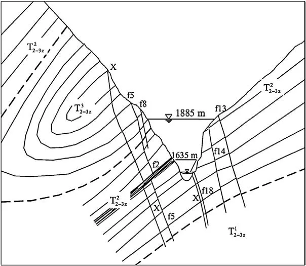
Fig. 1. Sectional diagram of geological structures across the valley in the project area.
The outcropping strata in project region are group T2–3z, the middle–upper group of Triassic Zagunao formation, which consists of the core parts of the dam foundation and southeast branch (normal branch) of the close inversed Santan Syncline. The rocks in the region can be classified into three groups according to their lithology. The first group is green schistwhich is buried in depth under the riverbed and does not outcrop on the ground. The second one is marble of green schist interbedsIt consists of eight layers observed in both banks of the river with thickness of about 600 m. This rock group contributes to the host rocks of the damfoundation,andinterlayerbeltsdevelopinthegreenschist rock masses. The third one is metasandstone and slateconsisting of six layers, with overburden thickness of about 400 m. It is formed in the core strata of Santan Syncline and can be found in upper left abutment. Rock mass integrity of this group is not good as expected because of its lithology and formation. The strikes of those strata are almost consistent with river flowing direction, dipping toward the left bank with an inclination of about 40°. Therefore, a typical longitudinal valley is formed, with consequent slopes in right bank and inverse slopes in left bank (Fig. 1).
Weak discontinuities, mainly in the presence of faults, are developed in the dam site, with predominating strikes of NE–NNE and dip of SE. Some large-scale weak discontinuities are of faults f5, f8, f2 and lamprophyre dyke X in left bank, faults f13, f14 in right bank, and fault f18 lying obliquely in the riverbed, which definitely control the stability of the project (Fig. 2).
Faults f5, f8 and lamprophyre dyke X are observed outcropping in the left bank, and the width of crushed zones in the faults is basically 2–8 m. These discontinuities are mainly composed of loose tectonic breccia, mylonite and strongly weathered rocks which are easy to dissolve in water. Owing to the unloading of valley slopes, the rock masses intersected by these weak discontinuities above the elevation of 1680 m are intensively fractured and loosened. Fault f2 outcrops in the lower slope in the left bank, consisting of four or five displacing interlayer belts with broken green schist rocks. Faults f13 and f14 develop in the right bank, with breccia and mylonite as their main composition, and mud with a thickness of several centimeters can be found in the faults. Fault f18 lies in the riverbed oblique to the right bank, and it is composed of lamprophyre dyke X, strongly weathered and susceptible to water (Table 1).
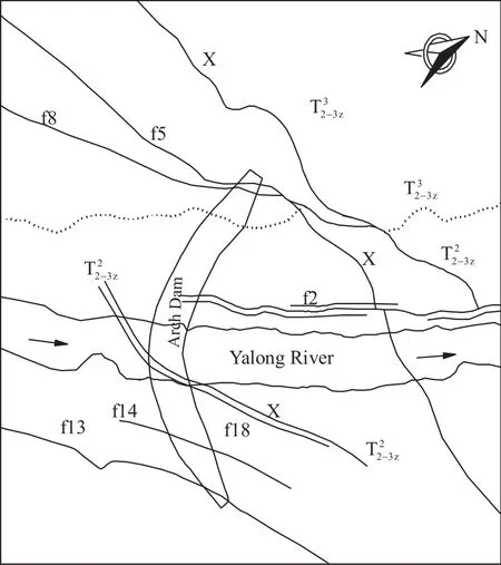
Fig. 2. Planar diagram of geological structures in the project area.
The rock masses are intensively unloaded in the slopes of the valley. In the right bank, the depth of unloading generally reaches 30–50 m, which is within a normal unloading scope. But in the left bank, the unloading depth of rock masses is considerably large due to the impacts of geological structures and rock lithology. In middle and lower slopes, this unloading depth of marble is 150–200 m, and that of sandy slate in middle and upper slopes can reach 200–300 m and even extend 500 m along the river side. Relaxed tensile fissures resultant from original joints can be frequently encountered in the unloaded rock masses, with apertures of 10–20 cm. This special geological phenomenon is rarely reported and thereafter is named as deep unloading (Qi et al., 2004; Song et al., 2011). The unique unloading feature in this region is the primary factor leading to the geological asymmetry of both banks. According to geological investigation in the dam site, the rock quality is classi fied as listed in Table 2.
3. Major geological defects in dam foundation and in fluences
It is previously mentioned that the geological condition in the dam site is signi ficantly asymmetric, relatively good in the right bank but unfavorable in the left bank. Thus a series of technical challenges for the dam foundation treatment are encountered. Through detailed analysis, the geological defects in dam foundation can be classi fied into two categories. One is the rock mass of grades III2and IV affected by unloading and ripping in dam foundation and resistance blocks of left bank, the other is large-scale discontinuities developed in the dam site (Liu et al., 2010).
According to the geological investigations and field excavations, rock masses of grades II and III1in this region account for 89.8% of rock masses of the right bank in total. In the left dam foundation, the rock mass quality of the upper part of slope is signi ficantly different from that of lower part. Below the elevation of 1780 m, the foundation surface is dominated by rock masses of grades II, III1, about 87.9%; while above that level, they are mainly of rock masses of grades IV–V, about 72.7%, and no rock masses of grade II can befound and that of grade III1only accounts for 15.1% of rock masses in total (Table 3 and Fig. 3).
It is noted that rock masses of grades III2, IV and V cannot be utilized as the foundation host rocks directly due to their unfavorable effects on stability of the dam foundation. After effective engineering treatments, rock masses of grade III2can be considered as the foundation host rocks. However, special treatments are desired for the rock masses of grades IV and V in the dam foundation.
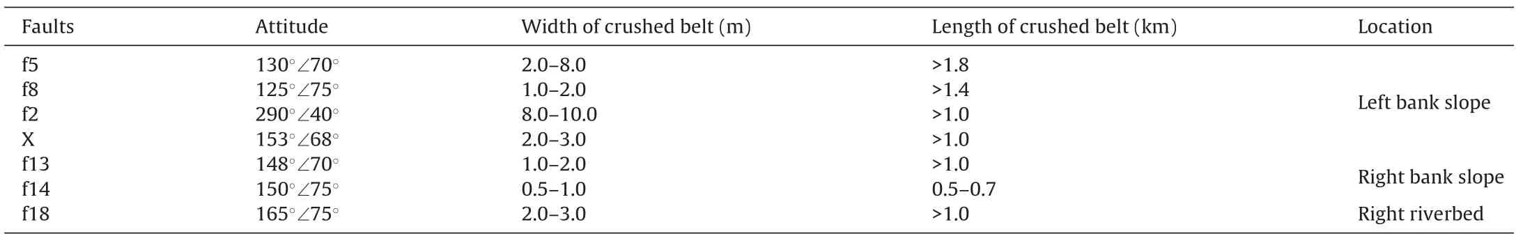
Table 1 Features of main weak discontinuities (faults) in the project region.
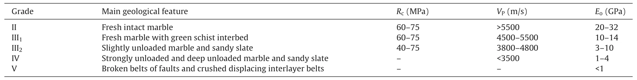
Table 2 Rock mass quality classification and physico-mechanical parameters in the dam site.

Table 3 Rock mass quality assessment of different parts in the dam foundation surface.
In the left valley slopes, the faults f5 and f8 featured with shallow overburden depth are observed, where fractured rock masses are widely distributed. The strongly unloaded rock masses outside the faults in combination of the faults exert adverse influence on the stability of the dam. Meanwhile, it is clear that the faults f5 and f8 attribute to the side boundary of potential sliding surfaces in the left abutment. Lamprophyre dyke X, buried in depth inside the slope, is strongly weathered, and its strike is almost perpendicular to the direction of the dam thrust, which also imposes unfavorable influence on the stability of the dam foundation. The lamprophyre dyke X similarly constitutes a potential boundary surface of certain sliding block in the left abutment (Song et al., 2010; Wang et al., 2012).
In the vicinity of riverbed, the faults f2 and f18 lie in the lower part of the dam foundation (i.e. elevation 1600–1680 m). Moreover, they are located in the main bearing zones of the dam foundation, and thus have major effects on the stress distribution and seepage stability of the dam foundation. The fault f2 composes a potential bottom surface of certain sliding blocks in the left abutment,and therefore it is unfavorable for the anti-sliding stability of the dam.
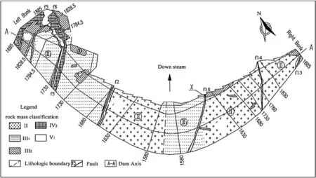
Fig. 3. Distribution diagram of rock mass quality in dam foundation surface (unit: m).
In the right valley slopes, the faults f13 and f14 outcrop in the upper part of dam foundation. For this reason, ground water signs show the layer has good permeability. It is interesting to note that the faults are interconnected with the reservoir in the upstream, and in the downstream they pass through the underground powerhouse area. In this way, the faults impose adverse influences on the stress distribution, transferring of the arch thrust, seepage stability and surrounding rock mass stability of underground powerhouses in the right abutment. Similarly, the faults f13 and f14 also constitute the potential boundary surfaces of sliding blocks in the right abutment.
4. Design of treatment for the geological defects
4.1.Conceptsoftreatmentdesign
Based on the disclosed geological conditions in the project region, effective engineering measures should be adopted to strengthen these defects and to analyze the in fluence of geological defects on the project stability. In the view of technical feasibility, concepts of treatment design for the geological defects in different locations in the dam foundation should be carefully proposed.
(1) The strikes of large-scale faults f5 and f8 are almost in parallel with the valley slope surface. The mechanical properties of those faults are very poor, thus excavation of the upper shallow parts of the faults and the slope rock masses outside them should be considered to improve the anti-sliding stability of the dam.
(2) The deep lamprophyre dyke X and the lower part of fault f5 are composed of very weak rock masses, which have a fairly wide in fluential zones, both of them dip toward the river. Local excavation in grids can be adopted, and after excavation it can be back filled by concrete or grouted directly, in order to improve the shear-resistance capability and the integrity of rock masses.
(3) Fault f2 outcrops in the lower part of the dam foundation and it extrudes the displacing belts and fault f18 that lies in the right of the dam foundation. The shallow parts are considered to be excavated after slots cutting in the foundation surface, and then concrete back fill can be implemented together with flushing and grouting in certain deep areas, so that the bearing capacity and anti-seepage properties of rock masses in the vicinity of these faults can be improved.
(4) Faults f13 and f14 are interconnected with the reservoir, and they have great impacts on stress distribution imposed on the dam foundation. Therefore, local places must be excavated and replaced with concrete. In addition, deep anti-seepage system and grouting are needed to reduce the negative in fluences of these faults on the stability of the right abutment and underground powerhouses.
(5) In the left dam foundation, the sandy slate above elevation 1800 m and the marble in the elevations of 1730–1800 m are quite fractured and the mechanical properties are considerably poor, which are directly associated with the faults f5, f8 and dyke X. Therefore, a massive concrete replacement cushion for those strata is needed; meanwhile, effective grouting will be implemented to improve the resistant capability of host rocks in this area.
(6) Drainage structures are considered in the downstream of the dam foundation, where anti-seepage curtains and resistance blocks are adopted.
4.2.Mainschemesoftreatmentdesign
4.2.1.Excavationdesignofabutments
The slopes in the right bank are mainly composed of marble that has relatively good mechanical property. The degrees of weathering and unloading depth of the marble formation are basically in a normal range, and the unloading depth is generally less than 50 m. The rocks in the depth below 50 m are almost fresh and classi fied into grade II or III1, a good choice for host rocks of the dam foundation. In this way, the scope of slope excavation is limited within the boundaries of the weathered and unloading belts in the right abutment.
The slopes in the left bank are roughly composed of sandy slate and marble. The rocks above the elevation 1750 m are intensively unloaded with depth more than 200 m, most of which are grades III2and IV and cannot be directly utilized as dam foundation surface. Particularly, in the elevation 1750–1730 m, fault f5 is in the vicinity of the arch abutment. The rocks around it cannot be considered as the dam foundation either for too small thickness of the layer on one hand, and on the other hand, excess excavation of the abutment will lead to large deformation of the arch dam and heterogeneous distribution of stresses in the dam (Xiang and Rao, 2008; Song et al., 2010). Therefore, the faults f5 and f8 and rocks around the faults (above elevation 1730 m) will be excavated in the left abutment.
4.2.2.Designschemesofconcretecushionsystemforweakrocks inthefoundationsurface
The concrete cushion in the left abutment is constructed in the elevations of 1730–1885 m. The thickness of the concrete cushion at different elevations is required according to the arch dam shape and the excavation scope of the spandrel groove.
In order to design an optimized width of the concrete cushion foundation, sensitivity analyses by finite element method (FEM) at the representative elevations of 1750 m and 1830 m have been conducted. Six schemes with different foundation widths in the contact surface of the cushion and bedrock are selected. The ratio of the foundation width to the arch abutment thickness at the same elevation is 1.4, 1.8, 2.0, 2.2, 2.4 and 2.6, respectively. The displacements of the arch abutment in the direction of arch thrust are adopted as evaluation index. The results indicate that, the displacements of the arch abutment at the elevation 1750 m, with values from 31 mm to 34 mm, tend to be stable when the width ratio reaches 1.8. While at the elevation of 1830 m, the relative ratio is 2.2, with displacement of approximately 15 mm. Therefore, the values of 1.8 and 2.2 are selected as the optimized ratios in the design of the width of the cushion foundation at the two elevations, which can be also referred to as a design principle at other elevations.
For the concrete cushion design, four schemes at the elevation of 1830 m have been implemented by two-dimensional (2D) FEM. Of these schemes, the width of the cushion at the side of the arch abutment is set to be 1.0, 1.5 and 2.0 times the arch abutment thickness, respectively. And different cases of slope excavation outlines of the spandrel groove are considered. Results show that the displacements of the arch abutment in the direction of river flow and the stresses in the cushion differ slightly with the width ratios of 1.5 and 2.0. The values of displacements and stresses are 18–24 mm and 1.0–1.5 MPa, respectively. However, the displacement is up to 44 mm and the principal compressive stress is up to 3.2 MPa when the ratio is 1.0. In consideration of both safety and economy, the width of the concrete is designed at 1.5 times the arch abutment thickness. The final layout of the concrete cushion is shown in Fig. 4, with average width and average thickness of 61.2 m and 49.8 m, respectively. The total concrete volume is 560.2 × 10³m3.
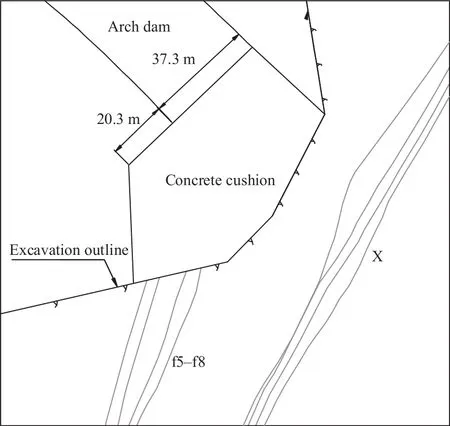
Fig. 4. Layout and dimensions of the concrete cushion at the elevation 1830 m.
In the cushion foundation, the rocks on the surface are unloaded, relaxed and weak. In order to improve the force-transfer effectiveness of the arch dam and the stress distribution in the rocks, five concrete replacement galleries are designed in the cushion foundation: one at the elevation of 1829 m, two at 1785 m and two at 1730 m, with sectional dimensions of 9 m × 12 m (width × height). These force-transfer shear galleries pass through the lamprophyre dyke X are situated in the intact rock masses, which are helpful for providing additional anti-shear capability of lamprophyre dyke X.
4.2.3.Treatmentdesignofconcretereplacementgridsforthe faultf5andlamprophyredykeX
In the left abutment, concrete replacement grids are adopted to treat the fault f5 and lamprophyre dyke X. Firstly, for fault f5 below the cushion foundation after excavation, two concrete replacement galleries at the elevations of 1730 m and 1670 m will be constructed along the strike of the fault. The height of the two concrete replacement galleries is 10 m, but the width varies according to the thickness of the crushed zones of the faults, basically 9 m in average. At the two elevations, four inclined concrete replacement shafts are employed along the fault plane, with a space of 30–35 m and a width of 15 m. The first shaft on the upstream also acts as an anti-seepage shaft of the dam curtains for fault f5, with a smaller width of 10 m (Fig. 5).
Secondly, for the treatment of lamprophyre dyke X, three concrete replacement galleries at the elevations of 1829 m, 1785 m and 1730 m are considered with sectional dimensions of 9 m × 12 m (width × height), which are intersected with the above-mentioned force-transfer shear galleries. In the elevations of 1829–1785 m, an inclined replacement shaft is implemented, together with the antiseepage curtains of the dam. In the elevations of 1785–1730 m, four inclined concrete replacement shafts will be constructed, with a space of 31 m and a width of 7 m (Fig. 6).
Fig. 7 shows a three-dimensional (3D) view of the designed strengthening system. It is composed of the concrete cushion, force-transfer shear galleries, and concrete replacement grids desired for the fault f5 and lamprophyre dyke X.
In the right abutment, fault f13 outcrops at the elevations of 1870–1885 m, with a relatively small area, which will be backfilled with concrete after open excavation. In the elevations of 1885–1601 m, inclined anti-seepage concrete replacement shafts will be constructed along the fault plane in consideration of antiseepage curtains of the dam, with a width of 5 m (Fig. 8).
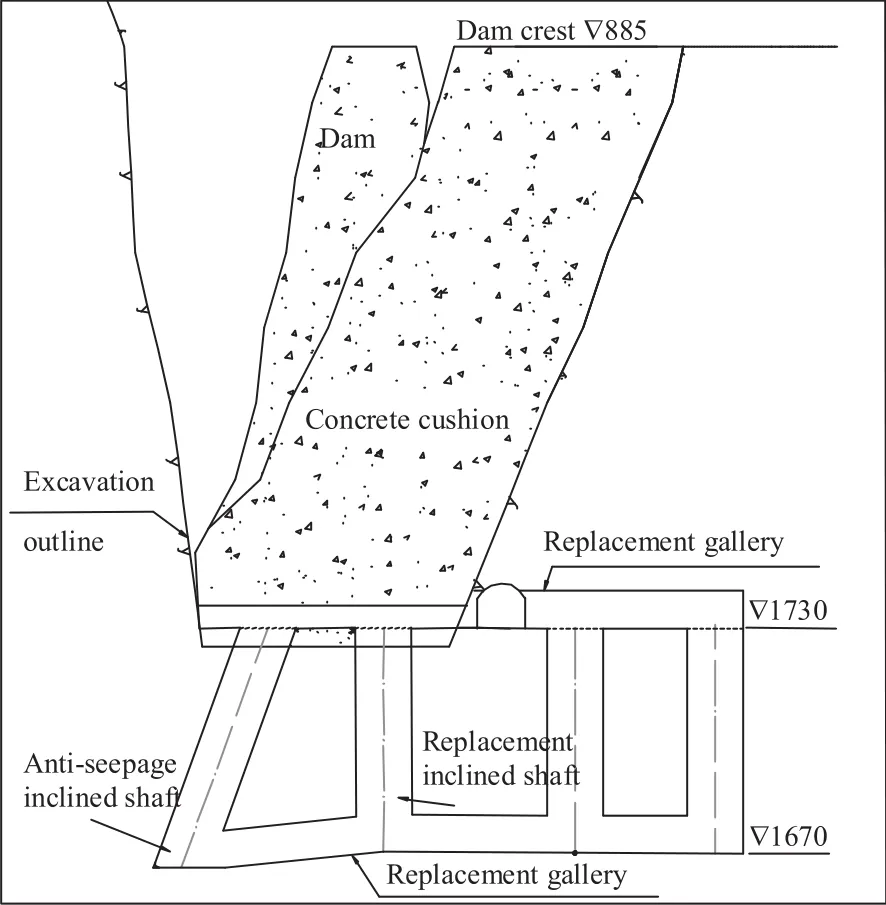
Fig. 5. Schematic diagram of the concrete replacement galleries and shafts for fault f5 in the left abutment (unit: m).
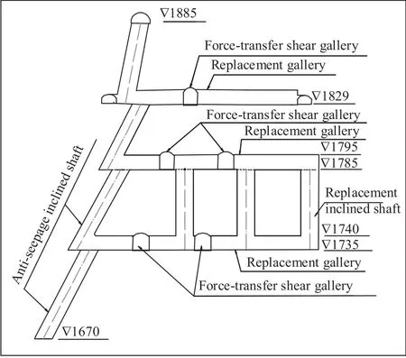
Fig. 6. Schematic diagram of the concrete replacement galleries and shafts for lamprophyre dyke X in the left abutment (unit: m).
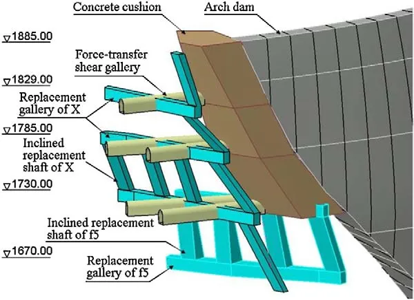
Fig. 7. Three-dimensional view of the concrete cushion, replacement galleries and shafts system in left abutment (unit: m).
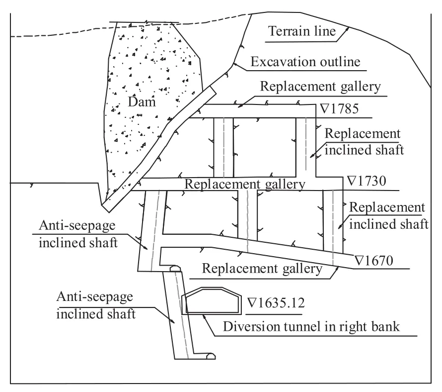
Fig. 8. Schematic diagram of the concrete replacement galleries and shafts for fault f14 in the right abutment (unit: m).
As for the fault f14, it outcrops at the elevations of 1740–1790 m, thus it will also be replaced with concrete after open excavation. Regarding of deep-seated parts of the fault, concrete replacement grids and intensive consolidation grouting will be employed, including three concrete replacement galleries at the elevations of 1670 m, 1730 m and 1785 m, respectively, with sectional size of 6.5 m × 10 m (width × height), and five inclined concrete replacement shafts (three between the elevations of 1670 m and 1730 m and two between 1730 m and 1785 m) with a width of 5 m. Intensive consolidation grouting will be implemented in rocks between the elevations of 1670 m and 1730 m, and an inclined concrete replacement shaft will be constructed in the elevations of 1601 m and 1730 m, with a width of 5 m. Thus they can function together with the anti-seepage curtain of the dam (Fig. 8).
4.2.4.Treatmentdesignoftheslot-cuttingreplacementand groutingforthefaultsf2andf18inlowerpartofdamfoundation andriverbed
Due to the similar conditions, the treatment measures for the faults f2 and f18 are almost the same as mentioned before. The outcropping parts of the faults will be excavated in consideration of slot-cutting and then be backfilled with concrete. Then cement grouting will be conducted in the foundation area around the deepseated parts. The design scheme of slot-cutting and excavation with an L-shape for the fault f2, as a typical case, is shown in Fig. 9. Moreover, the fault f2 imposes remarkable adverse effects on the seepage stability of the dam due to the weak and broken rocks in the crushed interlayer zones, a total thickness of 10 m. Additional measures are adopted for the site-specific fault f2, including high-pressure water flushing and grouting after drilling along the crushed interlayer surfaces, and cement-chemical composite reinforcing grouting in the vicinity of the dam and anti-seepage curtains.
4.2.5.Treatmentdesignofconsolidationgroutingforweakrock massesoftheresistanceblocksinleftdamfoundation
The resistance blocks in the left dam foundation basically consist of intensively unloaded rock masses grades III2and IV. Thus, effective treatment with consolidation grouting needs to be considered for the purpose of stability.
The elevations of grouting range from 1635 m to 1885 m. The lower boundary of grouting extends from weak rock to relatively high-quality rocks below the fault f2, including its interlayer crushed zones. The horizontal boundary is 5–10 m inside the influential zones governed by lamprophyre dyke X. The distance of grouting along the river bank is determined through sensitivity analysis of deformation by FEM.
Fig. 9. Schematic diagram of the slot-cutting replacement for the fault f2 and the crushed interlayer zones.
The sensitivity analysis is conducted by 2D FEM at two typical elevations, i.e. 1750 m and 1830 m. In the calculation model, the concrete cushion, the faults f5, f8, and the lamprophyre dyke X are considered, including the distribution of rocks of various grades. The results indicate that the displacement rate of the arch abutment decreases sharply at the elevation of 1750 m when the grouting distance along the downstream river bank is two times the thickness of the arch abutment (larger than 110 m). The displacements in the upstream and downstream sections are 27 mm and 46 mm, respectively. At the elevation of 1830 m, the displacements in the upstream and downstream sections are 17 mm and 21 mm, respectively, when grouting distance is 2.5 times the thickness of the arch abutment (larger than 95 m).
The results suggest that the distance of grouting along the downstream river bank could be determined in three elevations by considering the thickness of the arch abutment. Above the elevation of 1820 m, the rocks are mainly composed of sandy slate grades III2and IV, with considerably low rock quality. Therefore, the grouting range should be considered to somewhat large extent, and the ratio of the distance to the thickness of the arch abutment is determined as 3. In the elevations of 1820–1670 m, the rocks are predominately of grades III1and III2, thus the ratio of 2.5–2.7 can be adopted (Fig. 10). In the elevations of 1670–1635 m, most rocks are of grades II and III1, and the ratio is determined as 1.5.
According to the grouting principle of sliding-resistance, the quality of rocks after grouting should be grades III2–III1or higher. The detailed controlling standards of grouting are listed in Table 4.

Table 4 Requirements of rock quality after grouting.
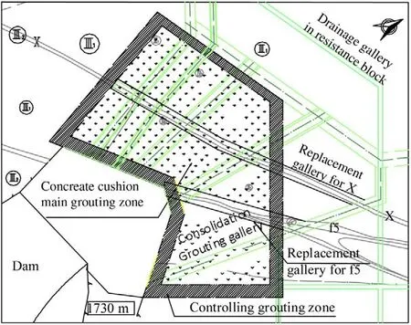
Fig. 10. Layout of the grouting area in resistance blocks at the elevation 1730 m.
In order to control the grouting quality and reduce the adverse influence of the grouting on the stability of the abutment slopes, the grouting area in the resistance blocks is divided into two zones, i.e. controlling grouting zone and main grouting zone. The controlling grouting zone is located in the margin of the grouting area with a width of 7.5–10 m. In this region, grouting will be implemented with relatively low-pressure and thick grouting, aiming at forming a protective closure against the main grouting zone. In the main grouting zone, grouting is conducted with high-pressure serum with various water-cement ratios. In particular, controllable grouting with cement mortar is adopted in deep fracture zones which contain large-scale and long fractures and may consume a considerably great amount of grout.
5. Preliminary evaluations of dam foundation treatments
The design schemes of treatments of the dam foundation were proposed in 2009. At present, the arch dam is constructed up to the elevation of about 1830 m. Concrete cushion and other measures for geological defects in the left abutment are almost completed except for grouting at the upper elevations. The impoundment of diversion tunnels has been realized. Results of geo-mechanical model tests, deformation monitoring, acoustic wave examinations of structures after impoundment indicate that treatments of the dam foundation are basically successful, and effectiveness of the design schemes has been preliminarily veri fied (Varga, 1979; Ronzhin et al., 1986; Xue and Huang, 2005; Mou et al., 2009; Hu et al., 2010; Song et al., 2011).
5.1.Geo-mechanicalmodeltests
Three geo-mechanical model tests for the stability of arch dam and its foundation were conducted in different stages (feasibility study, bidding, and design) before construction (Liu et al., 2003a,b; Zhang et al., 2005; Jiang et al., 2009). In the tests, the displacement, deformation and cracks of the dam foundation before and after treatment were measured, and the global factor of safety was calculated. Test results show that after treatment, the displacement of the crown was decreased from 105.3 mm to 85 mm under the normal load case. The factor of safety of crack initiation,K1, of the dam is increased from 1.5–2.0 to 2.5; the ultimate overload coef ficient,K3, is increased from 5–6 to 7.5. They are larger than those in most similar projects, which show that the asymmetrically deformable dam has been signi ficantly improved.
5.2.Qualityassurancetests
Quality inspections of grouting in resistance blocks below the elevation of 1730 m were conducted by acoustic P-wave tests, deformation modulus tests in drilling holes, and packer permeability tests. Test results indicate that, after conventional and intensive grouting, the average P-wave velocity in marble of grade III2is 5208 m/s, increased by 3.1%; the average deformation modulus is 12.3 GPa, increased by 28.2%. For marble of grade IV2, the average P-wave velocity is increased to 5184 m/s by 9.1%, and the average modulus to 10.5 GPa by 42.8%. Permeability rates in various rocks are kept in allowable values. It is indicated that all the indexes can meet the design requirements.
5.3.Monitoringresultsofdeformation,stressesandfractures
At present, the reservoir water level remains at about 1702 m. Monitoring results of deformation, stresses and fractures in foundation rocks indicate that the deformations in the dam foundation of both banks and galleries are considerably small with reasonable fluctuation. Distribution of compressive deformation in the riverbed is basically uniform, with a maximum value of 10.3 mm. The apertures of joints between the dam and the foundation are smaller than 1.0 mm. Stresses in the concrete cushion and the dams are mainly of compressive stresses. Monitoring results show that the deformation and stresses in the dam foundation are basically controlled.
6. Conclusions
Jinping I arch dam concerns many engineering issues and has attracted worldwide attentions due to its huge scale and unique settings. The geological conditions in the project region are extremely complex, characterized by serious geological defects, which pose great technical challenges on the project stability.
At present, the treatments have almost been completed, and the arch dam is still in the process of construction, and the final impoundment of the reservoir is not experienced yet. The performances of the dam and its foundation are pretty good at present. Numerical analysis, model tests, field excavation, quality inspection, and deformation monitoring indicate that the treatment schemes for geological defects in the dam foundation are effective. The concepts of treatment methods are helpful for similar dam foundations. It is strongly suggested that monitoring of the performances of the dam foundation be continuously conducted. Real-time analysis and dynamic design are needed in order to ensure the safety of the dam.
Fan Q, Zhou S, Li B. Key technologies of rock engineering for construction of Xiluodu super high arch dam. Chinese Journal of Rock Mechanics and Engineering 2012;31(10):1998–2015 [in Chinese].
Hu Z, Zhang J, Zhou Z, Rao H. Analysis of stress and deformation of Jinping I high arch dam after foundation reinforcement. Rock and Soil Mechanics 2010;31(9):2861–8 [in Chinese].
Jiang X, Chen J, Sun S. Research on physical model test for high arch dam of Jinping I hydropower station. Yangtze River 2009;40(19):76–105 [in Chinese].
Liu J, Feng X, Ding X, Zhang J, Yue D. Stability assessment of the Three-Gorges dam foundation, China, using physical and numerical modeling-Part I: physical model tests. International Journal of Rock Mechanics and Mining Sciences 2003a;40(5):609–31.
Liu J, Feng X, Ding X. Stability assessment of the Three-Gorges dam foundation, China, using physical and numerical modeling-Part II: numerical modeling. International Journal of Rock Mechanics and Mining Sciences 2003b;40(5):633–52.
Liu R, Liu F, Yu X. Design of consolidation grouting and treatment of geological defects for the foundation of the Three Gorges dam. Water Power 2004;30(3):18–21 [in Chinese].
Liu M, Huang R, Yan M, Lin F, Huo J. Preliminary evaluation of geological defects for rock foundation below left bank pedestal of arc dam for Jinping I power-station. Journal of Engineering Geology 2010;18(6):933–9 [in Chinese].
Mou G, Chen G, Liu R. Study on Jinping I arch dam left abutment foundation treatment. Design of Hydroelectric Power Station 2009;25(2):7–22 [in Chinese].
Qi S, Wu F, Yan F, Lan H. Mechanism of deep cracks in the left bank slope of Jinping first stage hydropower station. Engineering Geology 2004;73(1–2):129–44.
Ronzhin IS, Kanygin LE, Chernenko VN, Listrovio PP, Kim FG. Grout curtain in the foundation of the Nurek dam and evaluation of its effectiveness [Gidrotekhnicheskoe Stroitel’stvo, Trans.]. Hydrotechnical Construction 1986;9:18–21 [UDC 624.138.232.1:627.826.3].
Song S, Xiang B, Yang J, Feng X. Stability analysis and reinforcement design of high and steep slopes with complex geology in abutment of Jinping I hydropower station. Chinese Journal of Rock Mechanics and Engineering 2010;29(3):442–58 [in Chinese].
Song S, Cai D, Feng X, Chen X, Wang D. Safety monitoring and stability analysis of left abutment slope of Jinping I hydropower station. Journal of Rock Mechanics and Geotechnical Engineering 2011;3(2):117–30.
Varga AA. The main problems of evaluation of geological structure in dam construction. Bulletin of the International Association of Engineering Geology 1979;20:21–3.
Wang J, Duan S, Hu S. Treatment of high and steep slopes with complicated geological conditions at left abutment of Jinping I hydropower station. Chinese Journal of Rock Mechanics and Engineering 2012;31(8):1598–605 [in Chinese].
Xiang B, Rao H. Jinping I hydropower station dam site left abutment high slope complicated rock mechanics problems and engineering treatment measures. Design of Hydroelectric Power Station 2008;24(2):14–9 [in Chinese].
Xue L, Huang Z. Finite element method analysis of Jinping I arch dam foundation treatments effects. Design of Hydroelectric Power Station 2005;21(4):11–5 [in Chinese].
Zhang L, Fei W, Li G, Chen J, Hu C. Experimental study on global geomechanical model for stability analysis of high arch dam foundation and abutment. Chinese Journal of Rock Mechanics and Engineering 2005;24(19):3465–9 [in Chinese].

Shengwu Song,born in 1957, graduated from Wuhan Geology College in 1982, majoring in hydrogeology engineering geology. At present, he is the vice president of China Society for Rock Mechanics and Engineering (CSRME) and vice president of Chengdu Hydroelectric Investigation and Design Institute. He has been working on field investigation, design and research of hydroelectric projects for more than 30 years, and successfully designs over 20 large-scale projects in Southwest China, including Pubugou, Yele and Jinping I hydropower stations with complex geological conditions and challenging construction difficulties. He proposes two technological methodologies in dam constructions. One is the construction technology of dam with thick overburden, such as Pubugou and Yele hydropower stations on the Dadu River. This technology system includes bearing capacity, compressive deformation, liquefaction of sandy layer, and seepage stability issues on soft dam foundation. The other is the technology of rock masses stability controlling in high concrete dam construction, such as Xiluodu hydropower station on the Jinsha River and Jinping I hydropower station on the Yalong River. This technology system consists of analytical methods, reinforcement techniques and safety criteria, especially in high rock slopes and huge underground power houses. He is the principal investigator of a team that observed the deep-unloading phenomenon in sharply incised valleys in Southwest China and interpretation of its mechanism. The deep-unloading concept has been included in Chinese geological code as a new unloading type of rock masses.
∗Corresponding author. Tel.: +86 13908092641.
E-mail address: sshengwu@chidi.com.cn (S. Song).
Peer review under responsibility of Institute of Rock and Soil Mechanics, Chinese Academy of Sciences.
1674-7755 © 2013 Institute of Rock and Soil Mechanics, Chinese Academy of Sciences. Production and hosting by Elsevier B.V. All rights reserved.
http://dx.doi.org/10.1016/j.jrmge.2013.06.002
 Journal of Rock Mechanics and Geotechnical Engineering2013年5期
- Journal of Rock Mechanics and Geotechnical Engineering的其它文章
- Easy profit maximization method for open-pit mining
- A discontinuum-based model to simulate compressive and tensile failure in sedimentary rock
- Landslide disaster prevention and mitigation through works in Hong Kong
- Easy profit maximization method for open-pit mining
- Reply to Discussion on “A generalized three-dimensional failure criterion for rock masses”
- Discussion on “A generalized three-dimensional failure criterion for rock masses”