Effect of Several Key Parameters on the Dynamic Analysis of TTR
ZHANG Qi,YANG Hong-biao,HUANG Yi,ZHANG Ri-xi
(State Key Laboratory of Structural Analysis for Industrial Equipment,Department of Naval Architecture Dalian University of Technology,Dalian 116023,China)
1 Introduction
As China is going to explore South China Sea,dry-tree systems are attractive because they provide direct surface access to the well bore for maintenance and work-over activities and can enhance hydrocarbon recovery.TTRs are used to provide a dry-tree solution for floating production systems.And TTR system design and integration are identified as one of the key challenges facing with engineers.Because of the importance of the riser system reliability to profitable production of reserves,it is critical that the dynamic performance of the risers is accurately predicted during design.
In previous works,the dynamic analysis of risers has been widely discussed.Chung et al[1-3]investigated the coupled responses of a vertical deep-ocean pipe with excitations at pipe ends and external torsion.Ferrari et al[4]and Moroka et al[5-7]have studied about the dynamic behavior of general offshore risers.The modeling techniques of the riser have been presented by Mortazavi et al[8].The importance of structure and hydrodynamic nonlinearities on static and dynamic behavior of TTR has also been illustrated by Bae et al[9].Chang et al[10-11]studied the dynamic drilling riser subjected to random loads,and pointed out that the vessel motion rather than wave force is the principal dynamic loading of the riser.Though time consuming compared with frequency analysis[5],time domain analysis allows taking nonlinearities into consideration so as to achieve more accurate results,therefore,it is adopted in present study.
The design of a riser must include consideration of the many options of the size,pipe strength,the rig positioning and tensioning capabilities and the current profile and wave conditions.These factors have different relative effects upon the riser design.A sensitivity analysis which reveals the effect of these parameters is of great interest to those designing deepwater risers.
The present study aims to develop the modeling techniques and analysis procedures for a TTR with a stress joint.Also detailed responses for displacement,bending moment and stress are shown for the further investigation the sensitivity of dynamic effects to crucial parameters,such as,boundary condition,TTF and motion of the TLP.
2 Riser mechanical behavior and hydrodynamic load
2.1 Riser basic equation
A vertical TTR can normally be analyzed as an extensive beam under axial tension with lateral loads and effects of the hydrostatic pressure due to internal and external fluid.

where x is the lateral displacement of the riser,z is the vertical distance along the riser from the mud-line,Te(z)is the effective axial tension,M is the mass per unit length of the riser and is represented by:

where,Dois the outer diameter of the riser,Diis the inner diameter of the riser,ρsis the mass density of the riser pipe,ρmis the mass density of internal fluid enclosed in the riser.
2.2 Unidirectional hydrodynamic load
The hydrodynamic load Fx(z,t)in Eq.(1)is usually composed by two terms,drag force and inertial force,which depend on the relative velocity and the acceleration of the water particle with respect to the riser.
Generally,Fx(z,t)can be represented by modified Morison’s equation as follows:

where,F(x,t)is the in-line force per unit length,u is the wave particle velocity,ucis the x-directional current velocity,andare the riser acceleration and velocity of appoint along the riser,respectively.It can be calculated that
Eq.(1)can be discretized by using interpolation function,the finite element equation involving geometrically nonlinear responses of a pipe with large displacement is:

The accuracy of the results is directly dependent on a good selection of the hydrodynamic coefficients(CD,CM),usually the two coefficients are decided by experiment and then applied empirically to ocean.In general,a drag coefficient is a function of the Reynolds number(Re),riser surface roughness and Keulegan-Carpenter number(K-C).Typically the value of CMis in the range of 1.5 to 2.0 for a smooth circular cylinder[12].The value of Cin a post-critical
Dsteady-state is about 0.6 to 1.0[12].In this paper,the object riser is in a Re=2.55×10⁵,based on the recommended practice in the literature by Mousselli[13],we select two relatively conservative values:CD=1.0,CM=2.0.
3 Object riser description and simplification
The objective riser is designed for a TLP work in South China Sea at a water depth about 1 500 m.The riser system is mainly comprised of:riser joint,subsea well head connector,tensioners,stress joint and production tree.The riser consists of a production tubing and two(double-barrier)tubular around it(Fig.1(a)).Once the production tubing breaks,the outer pipe can still work.The inner riser acts as the primary pressure barrier for the production tubing.The stress joint is made of Titanium alloy,which is thought to be light enough and has a high yielding stress[14].
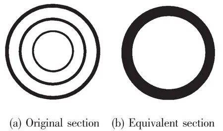
Fig.1 Riser section
In predicting the structural performance of such complex systems,it is imperative to use a fundamentals-based approach to arrive at simplifying modeling assumptions.
Global analysis of the very riser system is performed using an equivalent pipe model(Fig.1(b)).The equivalent pipe models are generated using the assumption that the riser section properties can be calculated from a compound section.Using this assumption,which ig-nores non-isometric properties,the riser properties are obtained by adding the areas,moments of inertia,effective tensions and masses of all of the tubulars together along the length of the riser.Riser is modeled by three-dimensional(12 degrees-of-freedom element)beam finite elements,which include the coupled axial and bending deformations.
The main dimension of the equivalent riser is shown in Tab.1.Specially,the parameter of the stress joint is given by Tab.2.
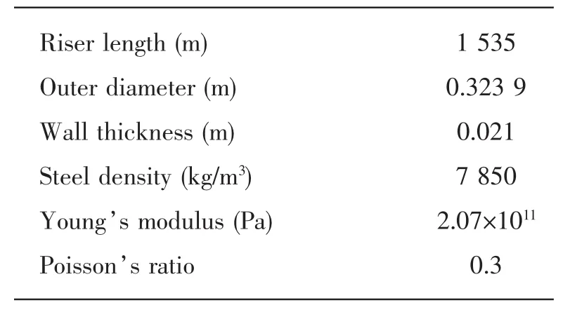
Tab.1 Main parameters of the riser
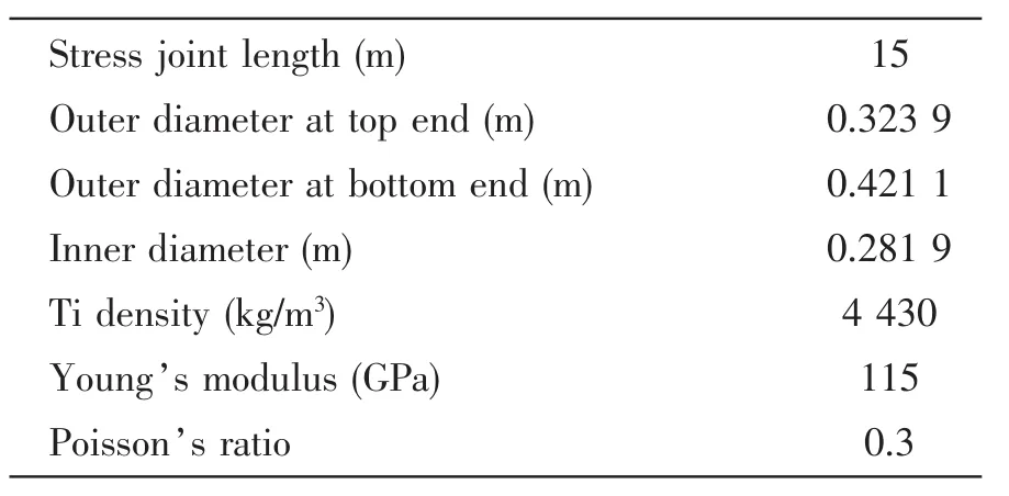
Tab.2 Main parameters of stress joint
4 Key factors in dynamic analysis of TTRS
4.1 Top tension factor
The tension of the TTR is provided by tensioners.The Top Tension Factor(TTF)is set to obtain a tensioned riser so as to avoid buckling and provide sufficient lateral stiffness for the riser.It is considered as a critical parameter for both tensioning systems and riser design.Top tension factor is usually defined as follows:

where,the effective tension at top is deemed as the net tension at the riser top.The riser apparent weight is riser weight in water,with the buoyancy and internal fluid into account.
4.2 TLP motion
The riser is connected with the TLP by a Hydraulic tensioner,so the riser top is driven by the motion of the TLP.And correspondingly the damping of the riser system also affects the TLP motion.
TLP motion usually consists of three parts:Static TLP offset,low frequency offset caused by wind and wave-drift forces and instantaneous response of the TLP to random waves.The motion may be calculated from the simulated waves and vessel frequency response function.
The TLP motion is calculated by Sesam/DeepC in present study.The motion of the TLP is coupled with riser risermooring lines by assuming the risermooring lines as massless nonlinear springs.
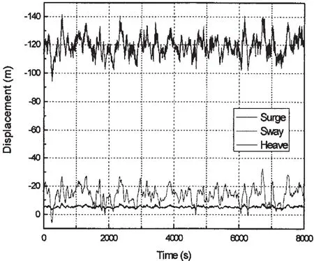
Fig.2 Typical coupled motion of the object TLP in extreme condition
According to the motion characteristics of Ten-sion Leg Platform,in present study,only three freedoms,surge,sway and heave,are considered.Fig.2 shows the particular coupled time history motions of the object TLP in extreme condition.This is used in the next calculations.
4.3 Environmental condition
The environmental condition of the TTR includes current profile and wave data.The current used profile is usually a monitoring data.The environmental condition is needed to assemble the design matrix of the riser.According to the statistical data of the South China Sea,the maximum wave height of the 100-year wave is about 15 m,and the zero-crossing period is about 10.4 s.Tab.3 shows the 100-year current profile which is used as extreme condition in the calculation.

Tab.3 100-year current profile
5 Results and discussion
The general FE analysis program ABAQUS has been chosen to model and simulate the TTR response.It is believed that the use of a general,nonlinear solver provides the necessary freedom to incorporate the proper physics without being forced to make unjustified simplifying assumptions due to software limitations.The use of this finite-element model solution procedure allows realistic modeling of the deep-ocean pipe configuration;this is complemented by an external force modeling due to(surface and subsea)environments,and fluid and flow properties.
5.1 Riser in extreme condition
In riser dynamic analysis,the response of the TTR in extreme conditions is of great interest.In the present study,the nonlinear irregular time domain analysis has been conducted for the very TLP production riser at 1 500 m water depth considering extreme South China Sea environmental conditions.The key data for the design are given in Tab.4.The data of the stress joint is the same as given in Tab.2.

Tab.4 Parameters of riser and environmental condition
Fig.3 shows that the envelope of the displacement of the riser in three directions.It can be easily seen from Fig.3 that the main deflation of the riser appears in the X direction which is parallel to the in-coming direction of the wave.The displacement in the Y and Z directions are relatively much smaller,so in the following study,we mainly concern about the lateral displace-ment of the riser in the X direction.
Fig.4 shows the envelope of the minimum and maximum bending moment around axis X.It can be noted that the bending moment varies a lot in the wave splash zone,in the lower part of the riser,bending moment experiences a stable stage during which its value is almost 0,then it goes dramatically high nearby the bottom of the riser.This should be mostly paid attention to in the design of TTRs.
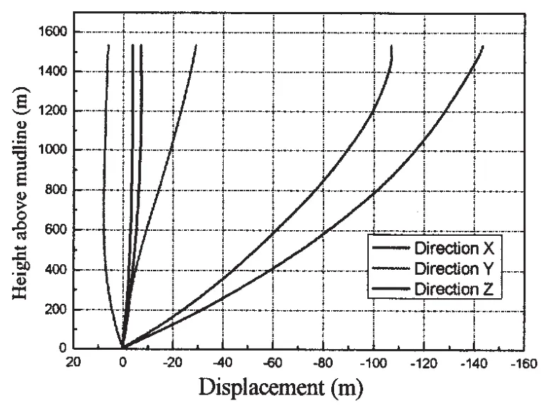
Fig.3 The envelope minimum and maximum of the displacement of the riser in three directions
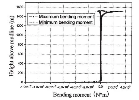
Fig.4 The envelope of the minimum and maximum bending moment around riser axis
As can be seen in Fig.5,the critical locations along the riser with relatively high stresses level are the stress joint above the subsea wellhead,and the splash zone.In the middle portion of the riser,equivalent stress decreases with the increase of the water depth.In general,the equivalent stress of the riser is well below the allowable stress.
5.2 Sensitivity analysis
The sensitivity analysis should be conducted under a coupled lateral and axial riser motion.Fig.6 shows the axial displacements at a depth=100 m under pure axial motion(excited only in z-direction)and coupled lateral-axial riser motion(exited not only in z-direction but also in x and y directions).

Fig.5 The maximum Equivalent stress along the riser

Fig.6 Axial displacements at a depth=100 m under pure axial motion and coupled lateral-axial riser motion
It can be seen that the motions in the lateral have a great influence on the axial behavior.The following analysis is all based on a coupled lateral and axial riser motion.
The design of a riser must include consideration of the many options of the size,pipe strength,the rig positioning and tensioning capabilities and the current profile and wave conditions.These factors have different relative effects upon the riser design.A sensitivity analysis which reveals the effect of these parameters is of great interest to those designing deepwater risers.
Lack of recognition of these sensitivities can potentially lead to more expensive and less reliable riser systems.Analysis and field measurement results indicate that the riser response magnitude is very sensitive to the mean pitch and position of the TLP.
5.3 Effect of TTF
In order to evaluate the effect of TTF,a variety of different values of TTF from 1.3 to 1.8 are adopted.Other parameters used in the calculation are the same as shown in Tab.3.
Figs.7-8 show the maximum displacement,equivalent stress of the riser under different TTFs.As expected,the deflection of the riser decreases with the increase of the TTF,this is because that the increase of the tension increases the axial stiffness of the riser.So,increase top tension is thought to be a way to prevent the collision of the riser.However the increase of the top tension also increases the equivalent stress of the riser in the top end,and it should also be noted that the equivalent stress at the bottom end of the riser increases with the decrease of the TTF,this is probably because the bottom end of the riser is greatly influenced by the current.Therefore,the design of TTF should be a consideration of both the top end and the bottom end of the riser.A good design should be a balance between the riser top end and the bottom end.
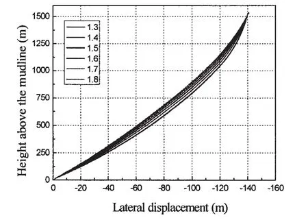
Fig.7 The envelope of the maximum lateral displacement along the riser under different TTFs

Fig.8 The envelope of the maximum equivalent stress along the riser under different TTF
5.4 Effect of TLP motion
Three different TLP motions are investigated;the mean offset of the TLP is 2%,4%and 6%of the water depth,respectively.TTF is 1.5 as a constant in the process.Other parameters used in the calculation are the same as shown in Tab.3.
Apparently,the lateral displace is very sensitive to the motion of the TLP,also it can be seen from Figs.9-10 that the bending moment in the most region of the riser increases little with the increase of the TLP motion.While the bending moment at the bottom,however,is very sensitive to the motion.When the motion increases only 2%,the bending moment at the bottom end of the riser increases nearly 50%.
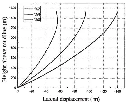
Fig.9 The envelope of the maximum bending moment along the riser under different TLP motions
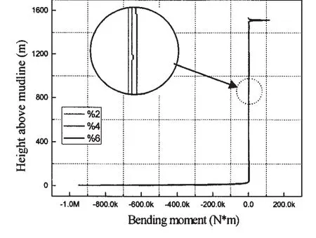
Fig.10 The envelope of the maximum bending moment along the riser under different TLP motions
5.5 Effect of current
Three cases of different current profile are taken in the study,the profiles of the three currents are shown as Fig.11.Cases123 represent for current in 5y10y100y typhoons,respectively.The other parameters are the same to those used in Tab.4.
Fig.12 and Fig.13 represent the result of the maximum displacement and bending moment of the riser considering different current profiles.The difference of the displacement and bending moments are not as significant as it should be expected.The riser’s displacement in the middle portion in Case3 is only about 3~5 m larger than in Case1.And the difference of the bending moment could only be seen in the top half of the riser as shown in Fig.12.This is possibly due to the fact that the current velocity is relatively large in the top half zone.
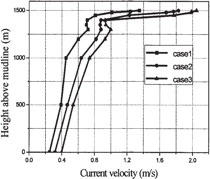
Fig.11 Three different current profiles
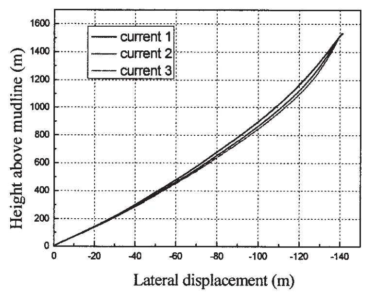
Fig.12 The envelope of the maximum lateral displacement along the riser under different current profiles
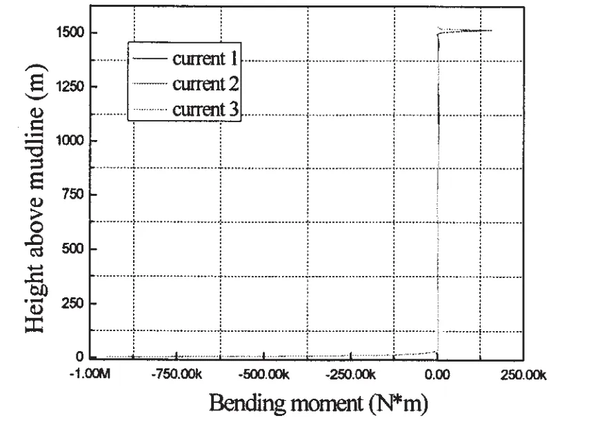
Fig.13 The envelope of the maximum bending moment along the riser under different current profiles
5.6 Effect of wave
Three cases of different significant wave height(H=5 m,10 m,15 m)are taken into account with the constant TTF(1.5)and zero crossing wave period(10.4 s).
The differences among the results of the displacement are subtle,in the present paper,only the curve of bending moment is given as in Fig.14.It can be observed that the wave only affects in the splash zone.And with the increase of the wave height,only a slight increase can be seen in the bending moment along the riser.It can be reckoned that wave parameter mostly influences the behavior of top tensioned riser indirectly by determining the vessel motion,while the direct influence on the riser is little.
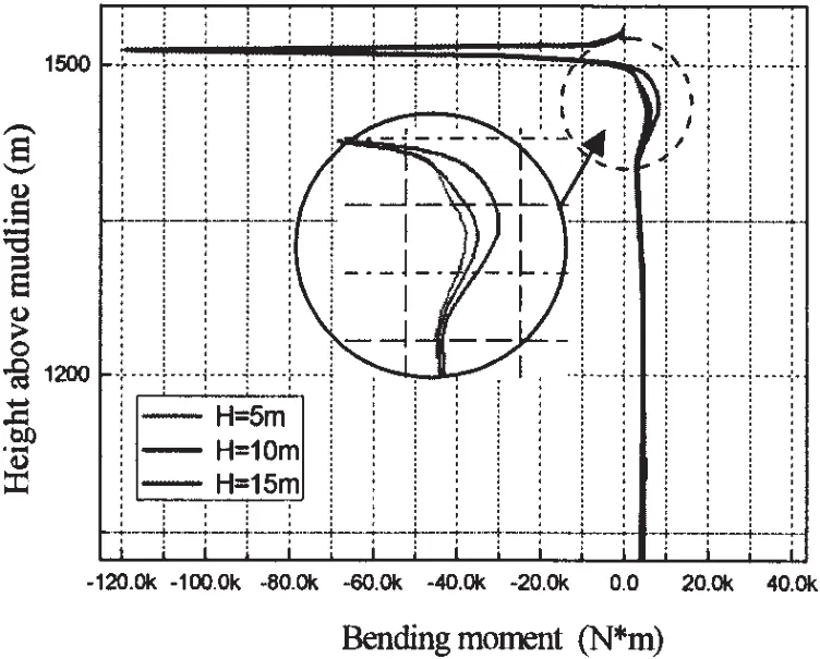
Fig.14 The envelope of the bending moment along the riser under different wave height
6 Conclusions
This paper mainly deals with a production TTR used in a TLP designed to serve in South China Sea.The investigations conducted here could be an important advancement to make possible the use of a vertical production riser with dry tree.Numerical simulations for TTRs have been carried out.Parametric evaluations for riser behavior are an important procedure to investigate the design of the riser system.Results emphasize the most important parameters for the riser’s dynamic behavior.The conclusions can be drawn as follows:
(1)Of all the three freedoms(sway,surge and heave)of the TLP motions,surge affects the most on the dynamic of TTR.
(2)Coupled lateral and axial riser motion should be considered when conducting TTR dynamic analysis.
(3)Lack of recognition of sensitivity analysis can potentially lead to more expensive and less reliable riser systems.The parameter that has the most significant effect for the 1 500 m depth riser is top tension and motion of the TLP.While the increase of the top tension reduces riser deflection,Simultaneously it increases the equivalent stress of the riser,a good design should be a‘balance’between the riser top end and the bottom end.
(4)Compared with TTF and TLP motion,current and wave both have limited effects on the dynamic behavior of the TTRs.
Acknowledgements
The work has been carried out at Ocean Engineering and Structure Safety Lab(OESS)of DUT and sponsored by the China National Hi-tech Research and Development Program(National 863 Program)No.2008AA09A105-04.The authors would also like to acknowledge China National Offshore Oil Corporation(CNOOC)for their support of the present study.
[1]Chung J S,Felippa C A.Nonlinear static analysis of deep ocean mining pipe-Part II:Numerical studies[J].Journal of Energy Resources Technology,1981,103(1):17-25.
[2]Chung J S,Cheng B R,Huttelmaier H P.Three-dimensional coupled responses of a vertical deep-ocean pipe[J].International Journal of Offshore and Polar Engineering(ISOPE),1994,4(4):229-239.
[3]Chung J S,Whitney A K,Loden W A.Nonlinear transient motion of deep ocean mining pipe[J].Journal of Energy Resources Technology,1981,103(1):2-10.
[4]Felippa C A,Chung J S.Nonlinear static analysis of deep ocean mining pipe-Part I:Modeling and formulation[J].Journal of Energy Resources Technology,1981,103(1):11-15.
[5]Ferrari Jr.J A,Bearman P W.Hydrodynamic loading and response of offshore risers[C]//Proceedings of 18th OMAE Conference.St.John′s,Canada,1999:4132.
[6]Moroka C K,Coelho F M,Shiguemoto D A,Franciss R,Matt C G C.Dynamic behavior of a top tensioned riser in frequency and time domain[C]//Proceedings of 16th ISOPE.San Francisco,2006(2):31-36.
[7]Morooka C K,Coelho F M,Ribeiro E J B,Ferrari Jr.J A,Franciss R.Dynamic behavior of a vertical riser and service life reduction[C]//Proceedings of 24th OMAE Conference.Halkidiki,Greece,2005(1):605-610.
[8]Morooka C K,Yokoo I H.Behavior of floating platform with marine riser in directional waves[C]//Proceedings of 2nd ISOPE.San Francisco,EUA,1992(1):628-635.
[9]Mortazavi M,Brad Campbell R,Brinkmann C R.Modeling and analysis of top-tensioned riser[C]//Proceedings of 20th OMAE.Rio de Janeiro,Brazil,2001:1168.
[10]Bae Y S,Bernitsas M M.Importance of nonlinearities in static and dynamic analyses of marine risers[C]//Proceedings of 5th ISOPE.Hague,1995,2:209-218.
[11]Chang Yuanjiang,Chen Guoming,Sun youyi,Xu liangbin,Peng Peng.Nonlinear dynamic analysis of deepwater drilling risers subjected to random loads[J].China Ocean Engineering,2008,22(4):683-691.
[12]Chang Yuanjiang,Chen Guoming.Theoretical investigation and numerical simulation of dynamic analysis for ultra-deepwater drilling risers[J].Journal of Ship Mechanics,2010,14(6):596-605.
[13]Design of risers for floating production systems(FPSs)and tension-leg platforms(TLPs)[S].API 2RD,1999.
[14]Mousselli A H.Offshore pipeline design,analysis,and methords[M].Tulsa:PennWell Publishing Co.,1981.
[15]Zhang Qi,Zhang Rixi,Huang Yi,Yang Hongbiao.Design and analysis of taper stress joint for top tensioned risers[C]//Proceedings of 20th ISOPE.Beijing,2010(2):23-28.
- 船舶力学的其它文章
- On-line Modeling of Ship Maneuvering Motion based on Support Vector Machines
- Experimental and Numerical Analysis of Bow Slamming and Whipping in Different Sea States
- Parametric Influence Analyses for Umbilical Installation in Deepwater
- Hydrodynamic Performance Analysis and Verification of Transverse Thrusters
- Improving of RSM-FORM and Application to Reliability Calculation of Ring-stiffened Cylindrical Shell
- Assessment of Ultimate Strength of Semi-submersible Platform

