Parametric Influence Analyses for Umbilical Installation in Deepwater
WANG Ai-jun,YANG He-zhen
(State Key Laboratory of Ocean Engineering,School of Naval Architecture,Ocean and Civil Engineering,Shanghai Jiao Tong University,Shanghai 200240,China)
1 Introduction
The umbilical is a critical component of floating production systems.It provides chemical injection,electrical power,hydraulic supply and signals to the subsea components for the control of subsea operations.Dynamic umbilical that connecting subsea wells to floating process facilities is a critical item in subsea production systems.It will be subject to high external hydrostatic pressure and environmental loads during the installation process.As the offshore exploration and production is increasingly moving into deeper water region,with accompanying increase in installation loads,the umbilical installation faces more challenges.Increased weight of umbilical would cause extremely high top tension.Wave and current induced motions are liable to introduce high stress in the umbilical,particularly at the touch down zone and hang-off position.High stress in the touch-down region can be reduced by installing the umbilical with buoyancy modules,rather than in a free-hanging configuration[1].The dynamic umbilical is deployed buoyancy modules to reduce high tension loads and protect the umbilical from excessive stress.Moreover,buoyancy modules are used to maintain a configuration such as lazy,steep,or pliant wave that allow the vessel a full range of surface movement without putting excessive stress upon the subsea lines.The vessel motion characteristics may dominate the umbilical configuration selection for the deep water application[2].So it is significant to study the effects of buoyancy modules on dynamic umbilical installation considering structure safety.In addition to its own weight,internal and external hydrostatic pressures,the umbilical are also constantly subjected to various dynamic forces like waves and currents[3].The response of the umbilical is very complicated.Therefore the effects of wave and current should also be considered during installation.
In recent years,several researchers have studied a lot of work about the umbilical installation.Clausing and Williams[4]introduced the first installation of lazy wave umbilical risers from a floating host.They discussed the difficulties encountered and the lessons learned during the buoyancy modules installation.Dieumegard and Fellows[5]reviewed the current installation practice and limitations of the umbilical installation in deepwater.Ellisor et al[6]discussed the technical challenges and lessons from Canyon Express umbilical installation.Their research focused on the experience and operation of installation.Wang and Yang[7]studied the stress responses of deepwater umbilical installation with different topographic parameters.The purpose of this work is to study the effects of different buoyancy modules deployment on umbilical and also discuss the effects of wave and current parameters for umbilical installation in deepwater.First,the free hanging catenary umbilical model is constructed on the basis of the catenary equation.Then the dynamic umbilical installation model is built up by applying buoyancy and other environment loads on the umbilical.The umbilical installation analyses with different sizes,length and deployment position of buoyancy module are discussed in detail.The installation analyses with different wave and current directions are also discussed.
2 Theory
The typical dynamic umbilical configuration with buoyancy modules is shown in Fig.1.L1is the bottom unbuoyed length of dynamic umbilical,L2is the buoyed length and L3is the upper unbuoyed length of dynamic umbilical.The total length of the dynamic umbilical is L=L1+L2+L3.D is the horizontal distance between the umbilical ends.In general,flexible risers are modeled as slender elastic structures[8].So dynamic umbilical can be modeled as a slender elastic structure.The governing equations of dynamic umbilical,based on geometry,moment-curvature relation and dynamic equilibrium,are


Fig.1 Dynamic umbilical configuration with buoyancy modules

where X,Y and rotation θ with respect to the X-axis are the coordinates of point on the dynamic umbilical.P and Q are the internal forces which are positive in the X and Y directions,respectively,and M is the bending moment.The subscripts S and T denote partial derivatives.The subscript j indicates that values vary according to the location along the umbilical length.When EjIj=EpIp,which is the bending stiffness of the unbuoyed umbilical along 0≤S<L1and L1+L2<S≤L.And EjIj=EbIb,which is the bending stiffness of the buoyed riser along L1≤S≤L1+L2.The buoyancy coefficient is Bj=1- (ρg Aj/Wj)and Fj=ρrjCdV2.The weight per unit length in the air of the unbuoyed umbilical and internal fluid is given by Wp.The steady current velocity is V,ρ is the seawater density,r is the radius and A is the cross-sectional area.Cdis the drag coefficient.U and μfare the internal fluid velocity and mass per unit length,respectively.
In the deep waters of South China Sea,Gulf of Mexico,West Africa and Norway,for example,where oil and gas exploration and production continue quickly[9].Dynamic umbilical analysis is very complex due to the highly geometrical nonlinearity and highly responsive dynamic nature in deepwater[10].With the development of oil and gas exploration to deepwater and ultra deepwater,current and vessel motion may produce more severe dynamic response[11].Furthermore,due to the complex internal structure of umbilical,it is very difficult to perform global dynamic analysis.According to the principle of bending stiffness equivalent,we simplify the umbilical.Probyn et al[12]proposed a bending stiffness calculation method for umbilical.In this work umbilical is simplified for global dynamic analysis using this method as follows:

where:Kbend=umbilical bending stiffness;Ei=Young’s modulus of component i;Ii=second moment of area of component i;Gi=shear modulus of component i;αi=helix angle of component i.
3 Case studies
Umbilicals are usually grouped into two categories:dynamic umbilical and static umbilical.Consequently,the umbilical installation includes two sequences:the buoyancy overboarding and the normal lay[13].Dynamic umbilical installation model is shown in Fig.2.At first,we build up the free hanging catenary model of umbilical according to the catenary equation,in order to obtain the model of umbilical with buoyancy modules quickly and effectively.Then buoyancy is applied on the umbilical to obtain the final configuration.Environmental loads in cluding wave and current load are also applied.The top hang-off is subjected to a heave motion coupling with FPSO.The wave and current parameters are shown in Tab.1 and Tab.2,respectively.The final configuration of dynamic umbilical is shown in Fig.3.
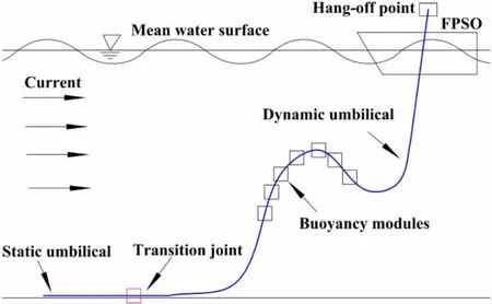
Fig.2 Dynamic umbilical installation model
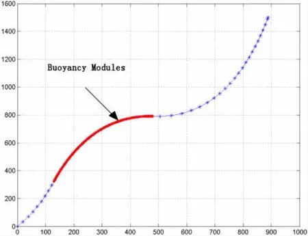
Fig.3 Configuration of dynamic umbilical

Tab.1 Wave parameters

Tab.2 Current parameters
4 Results and discussion
4.1 Installation analyses
Umbilical installation analyses,which are dynamic analyses in time domain considering environmental loads,are performed.The equivalent stress,axial force,curvature along the umbilical arc length,and top tension in time domain are shown in Fig.4.It demonstrates that maximum equivalent stress is at the top end in Fig.4(a).It decreases along the umbilical arc length and increases where buoyancy modules are deployed.At the bottom of deployed buoyancy modules,the stress reaches a local maximum.As shown in Fig.4(b),the axial force is similar to equivalent stress.From Fig.4(c),it can be seen that the maximum curvature is at the top of deployed buoyancy modules.The top tension meets the requirement of tension as seen in Fig.4(d).
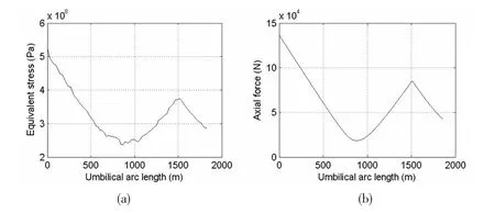

Fig.4 Installation analyses of umbilical
4.2 Installation analyses with different buoyancy module sizes
As demonstrated in Fig.5,the installation analyses of umbilical with different buoyancy module sizes are discussed.As seen in Fig.5(a),with the increase of the buoyancy module size,the increase rate of equivalent stress is not obvious at the top end of the umbilical but obvious at the bottom of deployed buoyancy modules and even exceeds the stress of top end.With the decrease of the buoyancy module size,the increase rate of equivalent stress is obvious at the top end of the umbilical and the equivalent stress decreases along the umbilical arc length.As shown in Fig.5(b),the trend of axial force is similar to equivalent stress.Fig.5(c)demonstrates that the maximum curvature rises as the increase of the buoyancy module size,but its position moves down.And the maximum curvature declines as the decrease of the buoyancy module size and its position moves up.The top tension rises slightly with the increase of the buoyancy module size as illustrated in Fig.5(d),but it increases significantly with the decrease of the buoyancy module size.It is found that the decrease of buoyancy module size is unfavorable to installation but beneficial to bending radius.
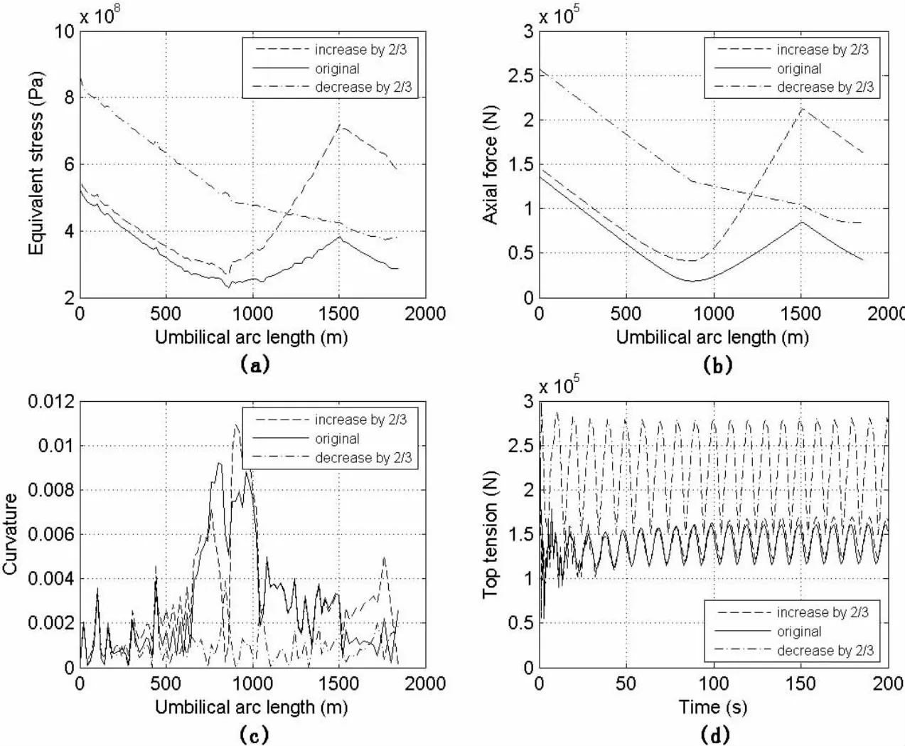
Fig.5 Installation analyses with different buoyancy module sizes
4.3 Installation analyses with different buoyancy module length
The installation analyses of umbilical with different buoyancy module length are discussed in Fig.6.The equivalent stress increases with the increase of the buoyancy module length and decreases with the length decreasing as seen in Fig.6(a).Fig.6(b)gives that the axial force varies in the same way as equivalent stress.As the increase of the buoyancy module length,the maximum curvature rises in Fig.6(c).It means that the bending radius reduces,which is disadvantageous to umbilical installation.Fig.6(d)demonstrates that the top tension rises with the decrease of the buoyancy module length due to the decline in buoyancy results in the top tension increasing.
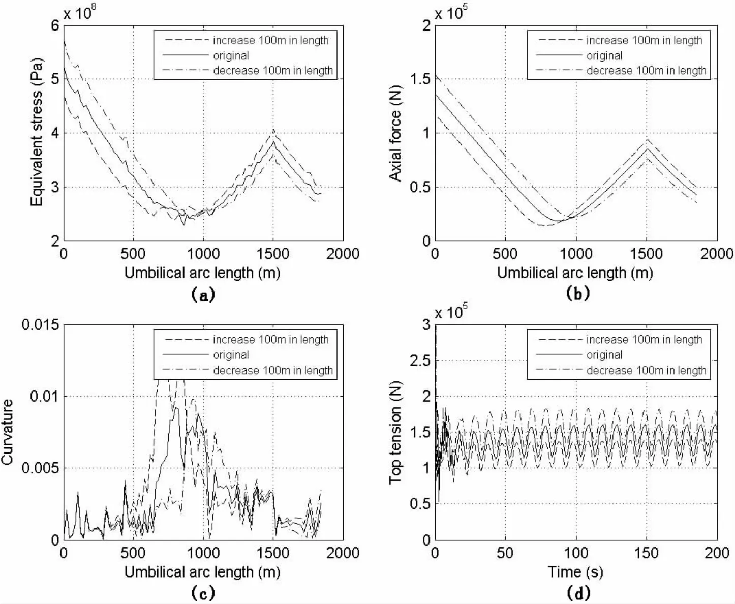
Fig.6 Installation analyses with different buoyancy module length
4.4 Installation analyses with different deployment position
The installation analyses of umbilical with different buoyancy module deployment position are illustrated in Fig.7.As the deployment position of the buoyancy module moving up,the equivalent stress increases as seen in Fig.7(a).The equivalent stress decreases as the deployment position moving down.In the same way,the trend of axial force in Fig.7(b)is similar to equivalent stress.As shown in Fig.7(c),the maximum curvature changes little as the deployment position of the buoyancy module moving up but it increases significantly as the deployment position moving down.As seen in Fig.7(d),the top tension rises as the deployment position of the buoyancy module moving up and it declines as the deployment position moving down.So the deployment position near the touchdown zone is beneficial if the bending radius does not infringe the allowable value.
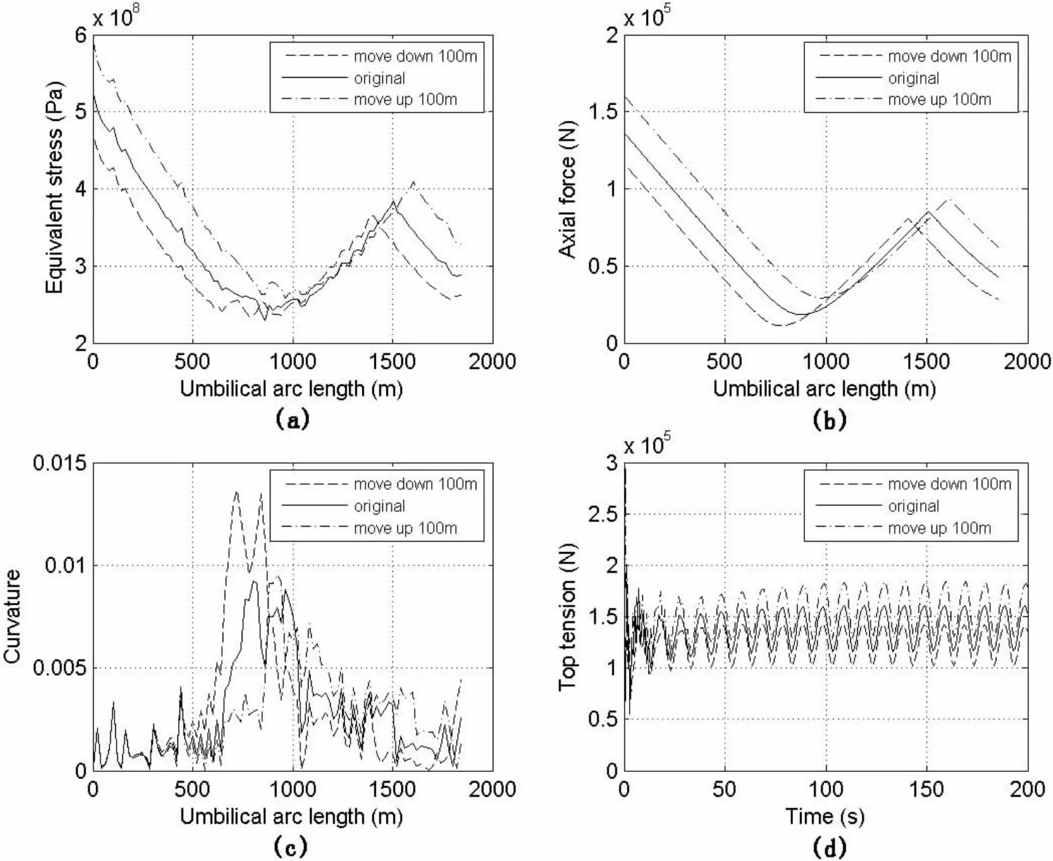
Fig.7 Installation analyses with different deployment position
4.5 Installation analyses with different wave directions
Installation analyses of umbilical with different wave directions are shown in Fig.8.Different direction waves:0°,45°,90°,135°and 180°are used to get the max equivalent stress,max axial force,Minimum Bending Radius(MBR)and max top tension during the installation analyses of umbilical,respectively.The maximum values of max equivalent stress,max axial force,MBR and max top tension are all in the direction of 45°and the minimum values of max equivalent stress,max axial force,MBR and max top tension are all in the direction of 0°.So wave in the direction of 0°is uniquely suited to umbilical installation if the bending radius meets the limiting criteria.Wave in the direction of 45°is unfavorable for umbilical installation.
4.6 Installation analyses with different current directions
As shown in Fig.9,installation analyses of umbilical with different current directions are discussed.Like waves,different direction currents:0°,45°,90°,135°and 180°are used to get the max equivalent stress,max axial force,MBR and max top tension during the installation analyses of umbilical respectively.The maximum values of max equivalent stress,max axial force,MBR and max top tension are all in the direction of 90°and the minimum values of max equivalent stress,max axial force,MBR and max top tension are all in the direction of 0°.So current in the direction of 0°is appropriate for umbilical installation if the bending radius does not infringe the limiting criteria.Current in the direction of 90°is unfavorable for umbilical installation,which should be avoided during installation.
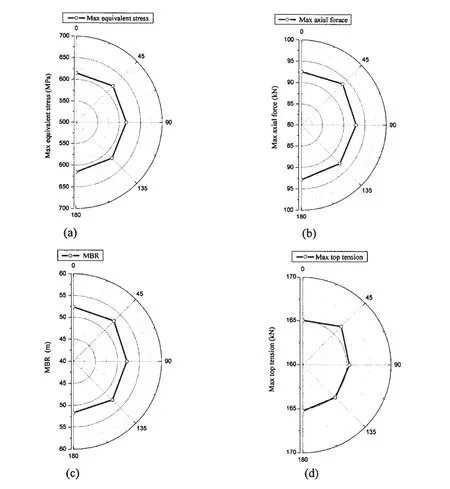
Fig.8 Installation analyses with different wave directions
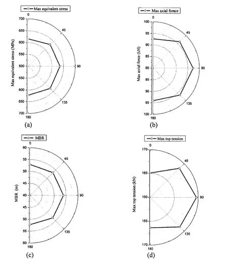
Fig.9 Installation analyses with different current directions
5 Conclusions
Parametric influence analyses for deepwater umbilical installation were performed in this work.The effects of different buoyancy module sizes,length and deployment position of buoyancy modules on umbilical were studied in detail.And the effects of wave and current directions were also discussed.Based on the results of this work,the following conclusions can be drawn:
(1)The buoyancy module deployment methodology has great effect on umbilical installation.The decrease of buoyancy module size and length is unfavorable to installation but beneficial to bending radius.The deployment position near the down zone is beneficial if the bending radius does not infringe the allowable value.It is notable that the bending radius conflicts with the top tension,stress and axial force.In order to reduce the top tension and stress,the bending radius should be paid attention to.
(2)Wave and current in the direction of 0°,which have the minimum values of max equivalent stress,max axial force,Minimum Bending Radius(MBR),and max top tension,are the best for umbilical installation if the MBR meets the limiting criteria.Wave in the direction of 45°and current in the direction of 90°are disadvantageous to umbilical installation,which should be avoided during installation.
[1]Yang H Z,Zheng W Q.Metamodel approach for reliability-based design optimization of a steel catenary riser[J].Journal of Marine Science and Technology,2011,121(3):129-133.
[2]Qiu W Y,Cao Q,Librino F,Hahn G,et al.Global design and analysis of umbilical in offshore Applications[C]//Proceedings of the 28th International Conference on Ocean,Offshore and Arctic Engineering.Honolulu,Hawaii,USA,OMAE2009-79841,2009.
[3]Yang H Z,Li H J.Sensitivity analysis of fatigue life prediction for deepwater steel lazy wave catenary risers[J].Science China-Technology Science,2011,54(7):1881-1887.
[4]Clausing K M,Williams V T,Macfarlane J C.Na Kika umbilical transport&installation challenges[C]//Offshore Technology Conference.Houston,OTC 16704,2004.
[5]Dieumegard C,Fellows P.Installation of metallic tube umbilicals in 3000 meters water[C]//Offshore Technology Conference.Houston,Texas,U.S.A,OTC 15368,2003.
[6]Ellisor T W,Martyniak P J,Wilson J V C.Canyon express deepwater umbilical and control system:design and installation[C]//Offshore Technology Conference.Houston,OTC 15099,2003.
[7]Wang A J,Yang H Z.Effects analysis of seabed topography on deepwater umbilical installation[J].Ocean Technology,2010,29(3):59-63.(In Chinese)
[8]Wang Y F,Pan Z Y,Huang X P,Cui W C.Effects of various factors on the VIV-induced fatigue damage in deep sea risers[J].Journal of Ship Mechanics,2006,10(5):76-83.(In Chinese)
[9]Wang Y F,Wu X Y,Pan Z Y,Huang X P,et al.Effect of elastic modulus on the VIV-induced fatigue damage in deep sea risers[J].Journal of Ship Mechanics,2007,11(6):867-878.
[10]Yang H Z,Li H J.Optimization design for deepwater risers with fatigue constraints[C]//Proceedings of the Twentieth(2010)International Offshore and Polar Engineering Conference.Beijing,China,2010.
[11]Chang Y J,Chen G M.Theoretical investigation and numerical simulation of dynamic analysis for ultra-deepwater drilling risers[J].Journal of Ship Mechanics,2010,14(6):596-605.
[12]Probyn I,Dobson A,Martinez M.Advances in 3-D FEA techniques for metallic tube umbilicals[C]//Proceedings of the Sixteenth(2007)International Offshore and Polar Engineering Conference.Lisbon,Portugal,2007:848-854.
[13]Felisita A,Gudmestad O T,Martinsen L O.Comparison of umbilical installation analysis using two irregular wave spectra[C]//Proceedings of the 29th International Conference on Ocean,Offshore and Arctic Engineering.Shanghai,China,OMAE2010-20145,2010.
- 船舶力学的其它文章
- Hydrodynamic Performance Analysis and Verification of Transverse Thrusters
- Improving of RSM-FORM and Application to Reliability Calculation of Ring-stiffened Cylindrical Shell
- Assessment of Ultimate Strength of Semi-submersible Platform
- Parameters Optimization of the Dynamic Absorber to Control the Axial Vibration of Marine Shafting System
- Anechoic Effect of Coating Covered on Target Submerged in Typical Shallow-water Waveguides
- 《船舶力学》稿约须知

