Parameters Optimization of the Dynamic Absorber to Control the Axial Vibration of Marine Shafting System
LI Liang-wei,ZHAO Yao,LI Tian-yun,LU Po
(School of Naval Architecture&Ocean Engineering,Huazhong University of Science and Technology,Wuhan 430074,China)
1 Introduction
Periodical force and torque due to the propeller in non-uniform flow field will cause shaft torsional vibration,axial vibration,lateral vibration and the coupling vibration.Oscillation caused by a small variation of thrust when the blades rotate through the non-uniform wake results in axial resonance at blade frequency[1].Many researchers have explored the axial vibrations of the marine shafting system,which are directly related to the quietness and comfort for passengers.A series of methods has been used for axial shaft vibration reduction,for example,by changing the stiffness of the marine thrust bearing,increasing damping in shafting foundation with the materials that have high damping properties,or using vibration control.One of the effective and feasible ways for vibration control is to install dynamic absorbers to marine shafting system.
The dynamic absorber attached to the primary system as a subsystem reduces vibration by introducing opposite force and also by dissipating energy through damping.The key to control the main system vibration is to clarify the parameters of dynamic absorber and locations.With the development of the different structural forms and the increasing needs of vibration control,the theory of parameters optimization has been improved.
The theory of dynamic vibration employed to one degree of freedom system without damping was first systematically investigated by Ding[2].Then,Randall et al[3]determined the optimal linear dynamic absorber for linear damping system based on minimum-maximum amplitudes criteria to find the optimal parameters.Because of popular application of the dynamic absorber in the field of machine engine,marine,automobiles,buildings,and so on,several researchers started to pay more attention to the methods of oversimplification to represent the original system.Ram and Elhay[4]studied the behavior of multi-degree-of-freedom vibration system with a simple dynamic absorber,and they proposed the recoverage of the physical parameters of a subsystem from the frequency response function measurements.Later on,a closed-form vibration transmissibility of a general unidirectional multi-degree-of-freedom system with multiple dynamic absorbers was discussed by Hsueh[5].Based on the graph model,the force and displacement transmissibility were derived by using the topology scheme.Two examples were shown for the implementation of this method.
Optimization and numerical algorithms were also presented in several literatures.Kitis[6]published a paper on the design of two dynamic absorbers simultaneously applied to an undamped cantilever beam with the re-analysis technique,and the design parameters were optimized by the method of feasible direction.However,in such parameters optimization of the dynamic absorber,only the optimal damping and stiffness were obtained except mass.A new geometrical design method used to simplify the stiffness matrix of dynamic absorbers for the multi-degree-of-freedom system was presented by Jang and Choi[7].Moreover,the performances of different frequency-tuning methods were examined by Sun et al[8].It was shown that the oneone method almost had the same characteristics as the optimization method,and it did not need time-consuming optimization process.
Dylejko et al[9]analyzed the propeller-shafting system with the four-pole parameter method and used the genetic algorithm to optimize the virtual resonance changer parameters.However,the transmission matrix parameters of the RC are not derived in detail and also the influence on different locations of the RC to decrease the axial vibration was not concerned.Viana et al[10]reported an analytical solution for the parameters optimization of two different dynamic absorbers by ant colony optimization and defined an objective function used to minimize the vibration amplitude of the primary structure.Furthermore,a comprehensive review of dynamic absorber including configurations developments and applications could be found in the papers by Kela et al[11].
After reviewing the literatures listed above,one should notice that most articles dealt with the theoretical models to optimize the parameters of dynamic absorber,while the practical en-gineering problems are less discussed.For example,little attention has been devoted to use dynamic absorber for specific resonance attenuation and solve the parameter optimization problems with the finite element method.Such problems do have considerable practical significance and therefore will be discussed in the following.
In this paper,the marine shafting system is modeled as multiple degree-of-freedom system based on the finite element method.The dynamic absorber is used to control the axial vibration of marine shafting system.It is essential to mention that the marine shafting system simply includes propeller,shafting,coupling,journal bearing and thrust bearing.The dynamic response of axial vibration is obtained by the re-analysis technique,which reduces the calculation time.The force transmissibility and the power transmissibility at the thrust bearing are derived to examine the performance of dynamic vibration.With the methods of the genetic algorithm and the multi-objective optimization algorithms,the dynamic absorber parameters are optimized over a certain response frequency range and the problem of specific resonance attenuation is also solved by adding equality constraint in the optimization process.Dynamic vibration is applied to three different locations at marine shafting system to investigate the influence on the axial vibration with different objective functions.The results here validate the feasibility of the optimization algorithm presented,and show that the vibration transmissibility is able to serve as a good criterion for the marine shafting system design as well as vibration control.
2 Finite element model
2.1 The axial vibration model of marine shafting system
The marine shafting system mainly consists of propeller,shafting,coupling,journal bearing,thrust bearing and their foundation.The components of simplified mathematical model are the lumped mass and axial stiffness,which make an impact on the behaviors of the shafting axial vibration.The axial vibration model of marine shafting system is shown in Fig.1.

Fig.1 The sketch of axial vibration of the marine shafting system
In order to get the motion equation of the axial vibration based on the finite element method,the marine shafting system is discretized into several elements.The position of the thrust bearing and the coupling should generate nodes according to the simplified criterion of the finite element model.The transmission shaft is generally simulated as beam element in numerical analysis.The mass of the propeller,the couplings and the thrust bearing are modeled as lump masses averagely assigned to their left and right element mass matrices.Similarly,the stiffness of thrust bearing is equivalent as axial stiffness averagely assigned to its left and right stiffness matrix.
The analytical expression of the beam element axial displacement is solved by using the appropriate displacement interpolation function combined with the boundary conditions.By assembling the matrix of the element,the motion expression of shaft axial vibration is obtained[12].
2.2 Model of dynamic vibration
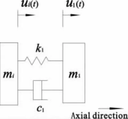
Suppose a single dynamic absorber attached to the marine shaft system along the axial direction at node i and the schematic is given in Fig.2,here miis the mass of marine shafting in the finite element model at node i.The dynamic absorber is composed of a virtual mass m1,a virtual stiffness k1and a virtual damping c1.The displacement of the masses at node i and the displacement of dynamic absorber are shown as ui(t)and u1(t),respectively.According to the D’Alembert principle,the dynamic absorber equation of motion is established as follows:

Fig.2 Dynamic absorber system

Substituting the Eq.(1)into the matrix forms:

After installing the dynamic absorber to the marine shafting system,Fig.3 shows the finite element model of axial vibration of marine shafting system,which has n nodes.Kthis the axial stiffness of thrust bearing and the hull is equivalent as rigid boundary.

Fig.3 The finite element model of axial vibration of marine shafting system
The motion equations of axial vibration of marine shafting system could be written as follows based on the performance of typical vibration system.

where[M],[K ]and[C ]are the mass,stiffness and damping matrices of this system.{F(t)}is the axial excitation force vectors.{u},{u˙}and{u¨}are the axial displacement,velocity and acceleration vectors,respectively.
3 Parameters optimization of the dynamic absorber
3.1 Solution of the vibration transmissibility
As an objective function to evaluate the performance of dynamic absorber,the force transmissibility and the power transmissibility are widely used.The marine structural vibration through the thrust bearing induced by shafting system is the main reason to analyze the axial vibration.This paper will discuss the effect of a dynamic absorber to reduce the axial vibration,using the force transmissibility and the power transmissibility at the thrust bearing as a criterion.
Suppose that the marine shafting system is excited by a periodically varying force with amplitude vector {F0},{F(t)}in Eq.(3)will be the form:

Correspondingly,the axial displacement vector of the shafting system is also written as:

where {u0}is the amplitude of the axial displacement vector.Substitution of Eq.(4)and Eq.(5)into Eq.(3),then takes the form:

When the dynamic absorber parameters change in the calculation procedures,the mass matrix,stiffness matrix and damping matrix in Eq.(6)will also regenerate.Define the parameter vector x as follows:

where q is the number of dynamic absorbers attached to the shafting system.
This paper will use the re-analysis technology to solve the equation of motion in Eq.(3),which could reduce the structure analysis time[6].When the dynamic absorber parameters change,the new mass matrice[M′],stiffness matrice[K′]and damping matrice[C′]of the vibration system in Eq.(6)could be expressed as follows:

where the Δ [M(x)],Δ[K(x)]and Δ[C(x)]are the variable quantity of each matrix and they are the function of the vector x.
In order to analyze the dynamic response described as Eq.(6),the initial values of dynamic absorber are required to start the numerical computation.Then,the matrices of the system are updated according to the Eqs.(8-10).Based on the solution technology dealing with the vibration problems of multiple degree-of-freedom system[13],e.g.,the substructure mode synthesis or model reduction,the displacement,velocity and acceleration from Eq.(6)can be finally obtained.
In the situation of the axial vibration of the marine shafting system,one can assume that the original system is excited a unit harmonically load at the propeller.With the Eqs.(6-10),the axial displacement as well as the axial velocity at each node could be solved.The force transmissibility and the power transmissibility at the thrust bearing are expressed as:

As shown in the above equations,T(x,ω)and W(x,ω)are the functions of three main variables at thrust bearing,the force FT,the axial displacement un-2and axial velocity vn-2.The interval ω⊂[ωmin,ωmax]is the response frequency range of the marine shafting axial vibration.
3.2 Objective function
Aiming to attenuate the axial vibration of the marine shafting system over the concerned response frequency range,appropriate algorithms should be explored to solve the design variables x of the dynamic absorber.It should be noted that the marine structure vibration through the thrust bearing is the main vibration transmission path.As a result,the response at thrust bearing is to be minimized over a frequency range ωmin≤ω≤ωmaxby attaching the dynamic absorber.Correspondingly,the objective function based on the force transmissibility and the power transmissibility is given by:

The physical meaning of Eq.(12)could be expressed as:the issue of dynamic absorber parameters optimization is to minimize the maximum value of the force transmissibility and the power transmissibility at the thrust bearing over the frequency range,and finally achieve the purposes of controlling the axial vibration of the marine shafting system.
3.3 Constraints
When the dynamic absorber is used to control the marine shafting system,the variables of dynamic absorber should satisfy the design requirements for parameters optimization.Define the xminand xmaxas the lower and upper limits of the design variables x,respectively,and the range of variables can be written as inequality constraints:

For the non-linear optimization problem in this paper,by combining the objective function in Eq.(12)with the constraints in Eq.(13)and choosing the external point penalty function method,one can express the regenerate objective function as objk′(x,ω,)R :

where R is the weight factor between the objective functions and the constraints.I is the number of inequality constraints.
3.4 Optimization algorithm description
The objective function described in Eq.(14) could be solved with different optimization algorithm techniques.Genetic algorithm is one of the most suitable methodologies,which is a search technique used to find the global approximate solutions to optimization.The significant advantage of the techniques for design values optimization is that there are no strict analytic objective requirements,and it is also suitable for a variety of variables,especially the discrete ones.The details of procedures for solving the Eq.(14)coupled with the genetic algorithm and multi-objective optimization algorithm are described in the following.
The response frequency band is first discretized.The vibration transmissibility described in Eq.(11)at the ith discrete frequency is written as Yk(x,ωi),where the ωiis the discrete frequency.Using the objective functions in Eq.(14)as the fitness functions,the maximum valuecan be obtained if the parameters of the genetic algorithm are defined,such as individual numbers,generation numbers,and variable precision.All the maximum values at discrete frequencies will constitute a vector,where the s is the number of discrete frequency point.Then,the maximum value of the vibration transmissibility is minimized with the linear weighting method to solve the multi-objective optimization problem.Finally,by transforming Yk(x,ωi)to the dimensionless form at every discrete frequency,the evaluation function is obtained to solve the objective function Eq.(14)based on the linear weighting sum[14].

where αiis the weighting coefficient which assigns the relative importance of the criterion and.Optimization problem described as Eq.(11)will change the analysis of the objective function(x,ω,R).Eq.(15)will be used to optimize the dynamic absorber parameters over the frequency range with the genetic algorithm and the multi-objective optimization algorithm.
4 Numerical example
4.1 Parameters optimization over 0-300 Hz
To illustrate the numerical method described above,an example of a marine shafting system is presented and a single dynamic absorber is used to control the axial vibration of the original system.The finite element model is established based on the sketch of the marine shaft system shown in Fig.4.

Fig.4 The finite element model of the marine shafting system
This sketch contains 19 nodes,17 beam elements,six lump masses and one axial spring.The three natural frequencies of the axial vibration in this example over 0-300 Hz frequency range are 51 Hz,122 Hz and 256 Hz.
The force transmissibility and the power transmissibility versus frequency of the original marine shafting system are shown in Fig.5.The following force transmissibility and the power transmissibility are calculated with base-10 logarithm.

Fig.5 The vibration transmissibility curve of the original marine shafting system
The paper is to study the characteristics of dynamic absorber at different positions in the marine shafting system.Since the transmission shaft mainly consists of the stern shaft,the intermediate shaft and the thrust shaft,the dynamic absorbers are applied to the three locations of the shaft segments shown in Fig.4,which are the location A,location B and location C.
The optimization parameters of dynamic absorber are solved with objective functions(x,ω,R)given in Eq.(15)based on the optimization algorithm shown above.In addition,the effect of different locations to control the axial vibration is explored.The lower limit and the upper limit of the dynamic absorber within the optimization process are shown in Tab.1.

Tab.1 The limits values of the dynamic absorber
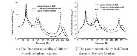
Using the force transmissibility at the thrust bearing as the criterion to solve the objective function in Eq.(15),the optimal values of the dynamic absorber are given in Tab.2,as well as the natural frequency f1.Fig.6(1)shows the force transmissibility versus frequency for the cases with dynamic absorber at three different locations.The resonance frequencies of shafting system and the amplitude of resonance peaks are different for the dynamic absorber at different positions.

Tab.2 Optimal values of dynamic absorber with the force transmissibility

Fig.6 The vibration transmissibility of different dynamic absorbers locations(over 0-300 Hz)
A comparison of the resonance frequencies of shafting system is shown in Fig.6(1).The first natural frequency becomes smaller than that of the shafting system without adding dynamic absorber.It is also clear from the figure that all the other resonance peaks,except the first peak,become lower than the corresponding resonance peaks without the dynamic absorber.As a result,after applying a single dynamic absorber to the original system,the second and third resonance peaks are suppressed when the optimal parameters of dynamic absorber are set.However,the first resonance peak attenuation is not obvious.
Simultaneously,the influence on the dynamic absorber located at three different positions in the first resonance peak attenuation is almost the same.The amplitude of second resonance peak is decreased obviously when the dynamic absorber is fixed on the intermediate shaft,and the amplitude of third resonance peak reduces more when the dynamic absorber is located at the stern shaft.
With the power transmissibility at the thrust bearing as the criterion to solve the objective function in Eq.(15),the optimal values of the dynamic absorber parameters are also given in Tab.3.A plot of the power transmissibility versus frequency curve with the dynamic absorber at three different locations is shown in Fig.6(2).

Tab.3 Optimal values of dynamic absorber with the power transmissibility
Comparing Fig.6(1)and Fig.6(2),the phenomenon of dynamic absorber on axial vibration absorption based on the two objective functions is almost the same.For example,the amplitude of the second and third resonance peaks become smaller when the dynamic absorber is applied to the three different locations.However,it is observed from the Fig.6(2)that there is an anti-resonance peak at the resonance frequency 122 Hz when a single dynamic absorber is attached at the stern shaft and the intermediate shaft.This value is equal to the second resonance frequency of the original system.It is demonstrated that the resonance peaks could be suppressed when the natural frequency of dynamic absorber is equal to that of the primary system.Therefore,parameter optimization of dynamic absorber is also the process of finding the appropriate parameters to solve the system oscillation at certain frequency.
4.2 Specific resonance frequency attenuation
The numerical example discussed above cares about the parameters optimization of the dynamic absorber over the entire frequency range.Providing that the problem of reducing the first resonance frequency has been increasingly a major concern,the method to suppress the first resonance frequency to control the axial vibration of original system will be presented as follows.
Based on the performance of the dynamic absorber to suppress the original system oscillation,an equality constraint will be added to the objective functions in Eq.(15).The method could enable the natural frequency of the dynamic absorber equal to the first resonant frequency.The equality constraint is expressed as follows:

where f1is the first resonance frequency of the original marine shafting system.
Substituting Eq.(16)into Eq.(15)to optimize the parameters of dynamic absorber,the new objective functions(x,ω,R,S)is given in Eq.(17)

where S is the weight factor of the equality constraints.The optimal values are obtained with the objective functions in Eq.(17),as shown in Tab.4 and Tab.5.

Tab.4 Optimal values for specific resonance attenuation with the force transmissibility
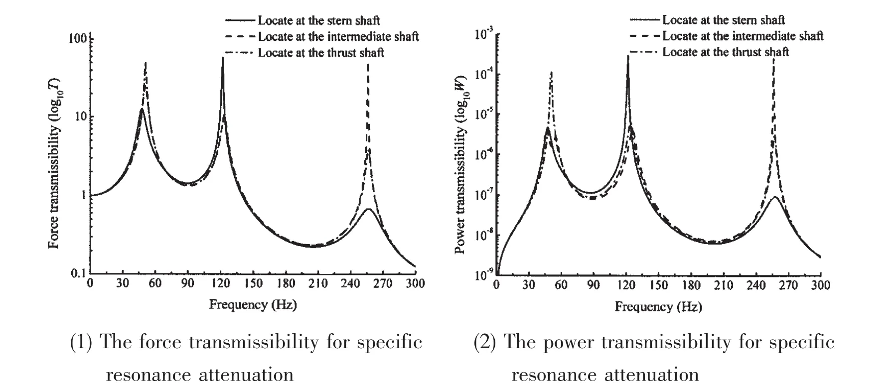
As can be seen from Tab.4 and Tab.5,for the dynamic absorbers at the three different locations,the natural frequencies of the dynamic absorber based on the two objective functions are close to the first resonance frequency of the original marine shafting system.It is demonstrated that the specific resonance could be attenuated by adding the equality constraint to the objective functions.However,the natural frequencies of the dynamic absorber are not exactly the same regardless of the different objective functions or different locations are chosen.It is the reason why the penalty factor and the number of genetic generation are used in the genetic algorithm process.With the force transmissibility and the power transmissibility to analyze the effect of specific resonance attenuation,the different curves are shown in Fig.7(1)and Fig.7(2).

Tab.5 Optimal values for specific resonance attenuation with the power transmissibility

Fig.7 The vibration transmissibility for specific resonance attenuation
The amplitude of the first resonance peak shown in the two figures is significantly suppressed.With the method of adding the equality constraint to optimize the parameters,the purpose of reducing the specific peaks could be achieveed.A comparison of the three different locations for the first resonance attenuation is presented.It is shown that the efficiency of attaching dynamic absorber to the stern shaft is better than that to the intermediate shaft.The amplitude reduction of the second and third resonance peaks is almost the same based on the two objective functions in Eq.(17),while the dynamic absorber installed to the stern shaft could be the best third resonance peak suppression.
5 Conclusions and discussion
Based on the previous results,we could draw the following comments and conclusions:
1)With the method of the genetic algorithm and multi-objective optimization algorithm,the problem of parameters optimization to control the axial vibration of the marine shafting system could be solved.Over the 0-300 Hz frequency range,the phenomenon of three resonance frequency reduction is similar with the two objective functions.
2)Comparing to the optimal results with the two objective functions over the 0-300 Hz frequency range,it is obviously proposed in this paper that the second and three resonance frequencies of the marine shafting system could be better attenuated with the optimization algorithm.However,it is shown that less effect is made to control the first resonance peak.
3)In order to suppress the first resonance peak,the equality constraint is introduced based on the characteristic of the dynamic absorber.Optimization results show that the method presented here could control the first resonance response.Comparison of the attenuation effect of different locations shows that,the three resonance peaks could be controlled better when dynamic absorber is added to the stern shaft.
[1]Xu Yunxiu,Zhong Xuetian,He Xuanxuan.Axial vibration of the ship shafting system[M].Beijing:China Communications Press,1985.
[2]Ding Wenjing.Theory of vibration absorption[M].Beijing:Tsinghua University Press,1988.
[3]Randall S E,Halsted D M,Taulor D L.Optimum vibration absorbers for linear damped systems[J].Journal of Mechanical Design,1981,103:908-913.
[4]Ram Y M,Elhay S.The theory of a multi-degree-of-freedom dynamic absorber[J].Journal of Sound and Vibration,1996,195(4):607-615.
[5]Hsueh W J.Vibration transmissibility of a unidirectional multi-degree-of-freedom system with multiple dynamic absorbers[J].Journal of Sound and Vibration,2000,229(4):793-805.
[6]Kitis L.Vibration reduction over a frequency range[J].Journal of Sound and Vibration,1983,89(4):559-569.
[7]Jang S J,Choi Y J.Geometrical design method of multi-degree-of-freedom dynamic vibration absorbers[J].Journal of Sound and Vibration,2007,303(2):343-356.
[8]Sun H L,Zhang P Q,Chen H B,Zhang K,Gong X L.Application of dynamic vibration absorbers in structural vibration control under multi-frequency harmonic excitations[J].Applied Acoustics,2008,69:1361-1367.
[9]Dylejko P G,Kessissoglou N J,Tso Y,Norwood C J.Optimization of a resonance changer to minimise the vibration transmission in marine vessels[J].Journal of Sound and Vibration,2007,300:101-116.
[10]Viana F A C,Kotinda G I,Rade D A,Steffen V.Tuning dynamic vibration absorbers by using ant colony optimization[J].Computers and Structures,2008,86(14):1539-1549.
[11]Kela L,Vähäoja P.Recent studies of adaptive tuned vibration absorbers/neutralizers[J].Applied Mechanics Reviews,2009,62(6):1-9.
[12]Zhang Zhihua.Numerical calculation of power equipment vibration[M].Harbin:Harbin Engineering University Press,1994.
[13]Clough R W,Penzien J.Dynamics of structures[M].New York:McGraw-Hill,1993.
[14]Zeng Guangwu.Optimization design of ship structure[M].Wuhan:Huazhong University of Science and Technology Press,2004.
- 船舶力学的其它文章
- Parametric Influence Analyses for Umbilical Installation in Deepwater
- Hydrodynamic Performance Analysis and Verification of Transverse Thrusters
- Improving of RSM-FORM and Application to Reliability Calculation of Ring-stiffened Cylindrical Shell
- Assessment of Ultimate Strength of Semi-submersible Platform
- Anechoic Effect of Coating Covered on Target Submerged in Typical Shallow-water Waveguides
- 《船舶力学》稿约须知

