Assessment of Ultimate Strength of Semi-submersible Platform
YE Qian,JIN Wei-liang,HE Yong,SHI Zhong-min,QU Yan
(1.Institute of Structural Engineering,Zhejiang University,Hangzhou 310058,China;2.Research Center of China National Offshore Oil Corporation,Beijing:100027,China)
1 Introduction
Nowadays it is a common practice to perform global strength analyses of floating structures as a powerful tool to design deep sea concepts such as Semi-submersible platform,Tension leg platform and Spar.The importance of this type of analysis grows due to increasingly novel and complex designs.This kind of structural design is usually different from those structures which are proved and already operating for a long time.So it is becoming an essential part of the safety check for novel and complex structures to carry out accurate assessment of the ultimate strength and the progressive collapse of the whole structure.During the past decades,a variety of methods including the simplified method(Smith’s method),the idealized structure unit method(ISUM)and finite element method have been developed for the estimation of the hull girder ultimate strength.Usually,simplified methods are applied for the progressive collapse analysis of ships and offshore structures.The applications of nonlinear finite element method are very few due to the consumption of computer resource and manpower especially for large scale structural model.However the rapid development of the computer technology makes it possible to carry out the nonlinear finite element analysis for the ultimate strength of floating structure with reasonable computation cost and proper modeling.This paper is a benchmark study of such analysis and the whole process is illustrated with a typical drilling semisubmersible platform.
Wave-induced responses of semisubmersible platform have been studied extensively for several decades.Lu and Xiao(2003)detailed calculating methods of wave load and used design wave method which is a stochastic method for selection of wave load acting on the semisubmersible platform.Lee et al(2005)described global loads and structure response analysis of a prototype semisubmersible and perform global strength analyses of the object platform.Ultimate strength of ships and offshore structures is a broad question and many papers have been published.Qi and Cui(2005)simplified a pushover method to calculate ship longitudinal strength which is especially useful for solving analysis of ultimate strength of damaged ship hulls and verify its validity by model tests.Paik(2008)conducted some benchmark studies on ultimate limit state assessment of marine structures by(unstiffened)plates,stiffened panels,and hull girders of ships levels.Different finite element software packages were used to make ultimate limit state assessment of these structures and simulation results were compared.
Ultimate limit state(ULS)of semi-submersible platform can be classified by global mode,local mode and interaction of these two modes generally due to complication of structure behavior and variation of load conditions.From a mechanism point of view,failure causes of semisubmersible platform include fatigue and fracture,buckling,yielding,corrosion,and so on.Each failure type can occur alone and it is more common that two or three kinds of failure problems may interact with each other.A real example of structural failure is Alexander L.Kielland.The collapse was caused by crack of a main brace and the whole platform was pushed over only for 14 minutes or so after the initial failure.Among others,Liu(2002)analyzed fatigue strength analysis of BingGO9000 semisubmersible drilling rig.Zhang et al(2005)calculated the ultimate strength of semisubmersible platform using a simplified progressive collapse analysis method.The focus of this paper is on evaluating ultimate strength of a twin pontoon semisubmersible platform using nonlinear finite element method.
In this paper,a finite element analysis method for the estimation of semisubmersible platform ultimate strength after an overview of global strength analysis for floating structure is presented.A numerical model is set up to study the ultimate strength of a typical drilling semisubmersible platform and a hydrodynamic model is built up with software package of WAMIT to generate hydrodynamic loads acting on the platform.The nonlinear finite element analysis is performed using the finite element code with ANSYS.The ultimate strengths are evaluated according to characteristic hydrodynamic responses of semisubmersible platform.A lot of infor-mation about the ultimate strength and collapse mode is provided on the nonlinear finite element analysis.Theoretical response descriptions from ABS rules and DnV rules can be clearly captured by the nonlinear FE analysis.The numerical model is verified against another model developed by SESAM program under the same wave condition.Numerical results are compared and commented.Some design suggestions are recommended and limit state formulations are developed.The results of the nonlinear FE analysis can serve as a benchmark reference to the analysis of ultimate strength of semisubmersible platform.
2 Assessment of ultimate limit state
Assessment of ultimate limit state of structures is usually by means of progressive collapse methods.The so-called progressive collapse methods include the simplified method(Smith’s method),the idealized structural unit method(ISUM)(Ueda et al,1984)and finite element method,and so on.Smith’s method and the idealized structure unit method have been already used to investigate the ultimate hull girder strength of ships widely.The main advantage of these methods is that they take advantage of analytic solution and can check the results of finite element method.Finite element method is not so often applied due to the high demand on computer resource.However,this situation is changing with the rapid development of the computer technology.The main advantage of the nonlinear finite element method is that no assumptions adopted in other methods are needed and interaction between structure components can be automatically taken into account.The nonlinear finite element method with proper modeling and analysis procedure is believed to be the most potentially accurate method for progressive collapse analysis of all kinds of structures.Nonlinear finite element method with ANSYS is used in the present paper.
Progressive analysis of semisubmersible platform is quite different from that of ships.Substantial difference is due to the complication of structure behavior.To assess ultimate limit states of semisubmersible structure,a typical pattern of analysis method for floating structure is reviewed and method for ultimate strength assessment is found to be slightly different.
2.1 Overview of global FE-analysis for floating structure
The intention of global FE-analysis is to assess structure responses resulted from global loads.It is a very time consuming technique and the following steps should be taken:
·Generation of a global finite element model
·Generation of loading condition and design wave load cases
·FE-calculation
·Calculation evaluation
·Drawing conclusions
2.2 Ultimate limit state assessment procedure of semisubmersible platform
Method for progressive collapse analysis process of semisubmersible platform follows global FE-analysis steps for floating structure to some extent.The differences of two procedures are in that the load of global FE-analysis is determined before analysis and that of progressive collapse analysis will be determined after analysis.Most steps of global FE-analysis method for floating structure are available to ULS assessment of semisubmersible structure.This section will present global FE-analysis steps in detail for process of progressive collapse analysis.
2.2.1 Finite element model
Many software packages are available for generating finite element models.Among others,ANSYS,ABAQUS and SESAM are widely used.Global FE-models shall represent the global stiffness and usually should be represented by three-dimensional shell model.The structure connections are important parts in the model and shall be modeled with adequate stiffness.Global model consists of a big amount of input data and therefore an overview of the model should be kept frequently.It is essential to check the FE model by a well grouped model structure and proper model documentation.The detailed information of the global structure model of the object platform will be presented in the next part of this paper.
2.2.2 Load generation
The most significant environmental loads for semisubmersible platform are normally those induced by waves.Several kinds of global responses to wave load are usually governing for the global strength of semisubmersible platform and characteristic of these wave responses are showed in Fig.1.Another important global response like ships is vertical wave bending moment on the pontoon Mbin a head sea.For these loading conditions design wave load cases have to be created which need to meet the requirements given in rules or values coming from direct load calculation.In survive condition,Fs,FL,Mtand Mbare in the most critical.
Wave loads on hull structure are usually calculated by hydrodynamic software packages.As well as others,SESAM,WAMIT,AQWA,HYDROSTAR are well known in offshore industries.A hydrodynamic model should be built to generate wave load on the object platform.After generation of wave load,user defined selection criteria,such as the maximum values of sectional forces and moments,and specified which waves have to be chosen for the global analysis.Some thousands of wave parameter combinations are scanned to select the worst load cases.About 6~7 load cases for each kind of condition(survive condition,operation condition,transit condition)are taken as the most unfavorable load cases for the finite element calculation according to characteristic hydrodynamic responses.The focus of this paper is the platform in survive condition.
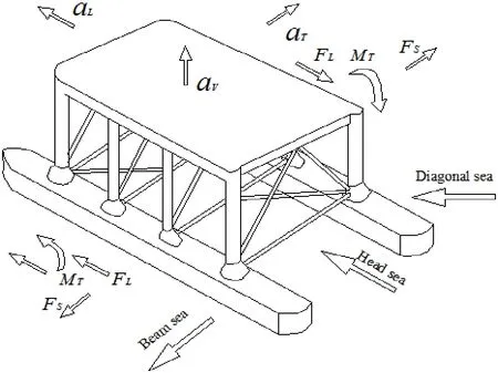
Fig.1 Characteristic hydrodynamic responses of semisubmersible platform
2.2.3 Calculation
To calculate structural response accurately,three types of load effects including external pressure loads,mass-acceleration terms and additional load types should be under consideration.External pressure loads are produced by contact with their environment and mass-acceleration terms resulted from motion of vessel.These two types of load are usually generated by hydrodynamic analysis.Additional loads such as variations in personnel,laydown and other live loads are not included in the motion analysis and generally insignificant for global stress.These loads may be important on local structure.Mass effects are significant to the calculation of floating structure.The following terms should be included:structural mass equipment loads,personnel,stores,fuel,etc.Structure and other masses should be distributed over suitable areas or smeared into the structure mass.Misdistribution of masses or large lumped masses will result in unrealistic point reactions.One useful method of dealing with this problem is to artificially increase the density of structure steel by region,to account for equipment,etc.It is important that identical masses should be represented in hydrodynamic and structure analysis.The centroid and second moment of mass about each axis should also be accurately calculated.This requirement is due to assumptions adopted in hydrodynamic analysis.
Semisubmersible vessel in harsh environment is a complicated dynamical problem.Dynamical factors must be considered for some instances(slamming and impact load).Quasistatic structure analysis is a relatively simple approach and can provide good prediction of the platform structure response under regular wave conditions.The load cases must be well balanced,which means platform acceleration forces are in equilibrium with forces from water pressure.Calculation of global FE-model is a very time consuming job despite of many efforts in the development of this technique.During the last decades the demands on strength analyses have increased rapidly and fortunately the computation capacity has increased,too.Therefore computation restrictions no longer exist in most cases.
2.2.4 Evaluation
Calculation evaluation of global FE-analysis is according to the rules and standards and should cover the following items:
·Deformations
·Stresses
·Buckling
·Ultimate strength
·Fatigue
To ULS assessment,it is not necessary to evaluate all of these items.Deformations,stresses and ultimate strength are the main concerns for ultimate limit state of semisubmersible platform.Deformation,stresses and ultimate limit state should be in consistence with each other and that is a precondition to gain confidence in calculated results.
2.2.5 Drawing conclusion
Drawing conclusion is a necessary job of structure analysis.Comment on structure design and recommendation or proposal are required in this step.To ultimate limit state assessment of semisubmersible platform,it is also an important step to give some insight on the final collapse state especially failure mechanism of the structure.
2.2.6 Ultimate limit state assessment procedure
ULS assessment procedure is quite similar to that of global FE-analysis.A global structure model should be built first.And a hydrodynamic model is built to generate wave load on the structure.After load generation,some thousands of wave parameter combinations will be scanned to select the worst load case.Selection criterion such as the maximum value of section load(Fs,FL)or bending moment(Mt,Mb)specified which waves have to be chosen for the global analysis.Calculation of the global FE-model and evaluation of numerical results are with finite element software package.Conclusion should be drawn about the structural behavior and comment on imperfection of design.One of disadvantage of adopting finite element method is its uncertainty.Ultimate strength behavior is often affected by various parameters such as initial deflection shape of structure and boundary conditions and load conditions,etc.It is especially true for floating structures such as semisubmersible vessel,tension leg platform,etc.So the whole process of FE-analysis should be strictly abided by.And the more important thing is to verify the numerical results by various means such as a simplified model,comparison with experimental results or numerical results calculated by different software packages.

Fig.2 Flow chart of numerical solution procedure for global ultimate strength assessment
Software package ANSYS is used for structural model and WAMIT is used for hydrodynamic model.ANSYS includes preprocessing tools,solver as well as post processing tools with a friendly graphical user interface.WAMIT is famous for accurate prediction of hydrodynamic loads on hull structure.To regular sea wave,the wave loads acting on the object platform are proportional to wave amplitude Ad.Progressive collapse analysis is achieved by applying wave amplitude Adfrom a relatively small one and increasing it step by step.When the result of one load step is not convergence,the load is assumed as the limit load.Fig.2 illustrates a typical ultimate limit state assessment process employed in this paper.
3 Global structural model
The object platform of the present study is a typical drilling semisubmersible platform.It has two parallel pontoons with bracing connecting them.To predict the structure behaviour accurately,a well-represent finite element model should be first built and nonlinear finite structure model is built up with the finite element code ANSYS.
3.1 Geometric of the object platform
Tab.1summarizes the principal dimensions of the object semisubmersible platform.The dimensions of main structure part including pontoons,columns,horizontal braces and deck and their relative dimensions with each other are roughly illustrated in Fig.3.
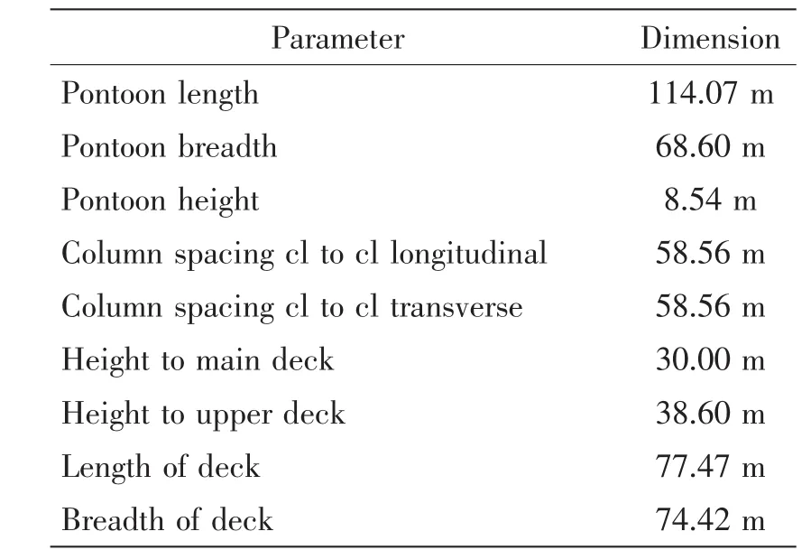
Tab.1 Principal dimension of the object platform
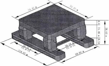
Fig.3 Principal dimension of the object platform
3.2 Material properties
For assessment of ultimate strength of the object platform,it is important to establish the nonlinear material model in terms of stress versus strain relationship.The elastic-perfectly plastic material model is adopted by neglecting the effect of strain-hardening.The majority part of platform structure is made of EQ36 with only a small part of structure around middle column made of EQ56 for transition.For numerical model,EQ36 is adopted for the whole structure with yield stress σYof 355 MPa,Young’s modulus E of 206 GPa and Poisson’s ratio υ of 0.3.
3.3 Loading condition
Load condition will be determined after generation of wave load.Selection of the most un-favorable waves is in terms of design wave approach.It is an approach based on stochastic approach.The detailed method of this approach can been found in DNV rules and ABS rules.Environment criteria are built based on wave statistics of South China Sea.For nonlinear finite element computations,four kinds of load cases including split force (FS),shear force (FL),torsion moment (Mt)and bending moment (Mb)are used as candidate load cases.Their corresponding characteristic responses are shortly summarized in Tab.2.The wave parameters are listed in Tab.3.Wave direction angles are from the bow and wave amplitudes Adis based on maximum hundred years.The wave amplitudes in Tab.3 are calculated by statistic wave steepness of South China Sea and can serve as a reference to ULS analysis.Response amplitude operators(RAOs)of main section load SFis a load of per unit wave amplitude to corresponding design wave and Maximum of them is listed in Tab.3.
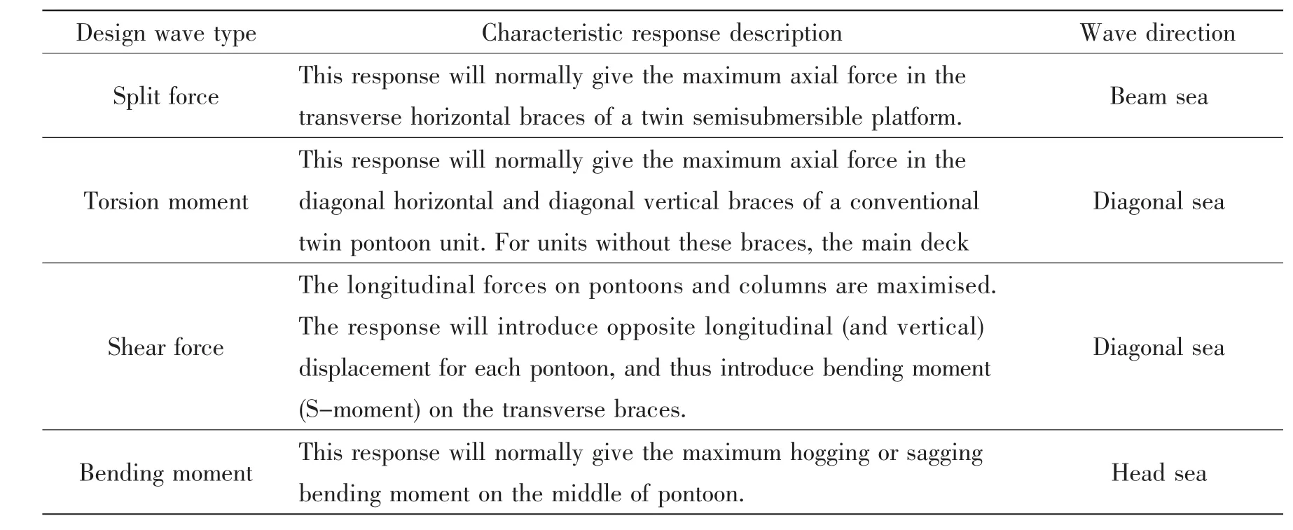
Tab.2 Theoretical response description for typical design wave

Tab.3 Wave parameters selected by design wave method
3.4 Nonlinear finite element mesh modelling
The nonlinear finite element model for the object platform is built up with the finite element code ANSYS.The model used in the present study is illustrated in Fig.4.The main structure of semisubmersible platform consists of pontoon,column,deck and brace.Each part of them may be divided into sub-structural elements such as bulkhead,girder,stiffener,etc.Global FE-model shall represent global stiffness of structure and the model should be represented by a large volume,thin-walled three-dimensional shell(represented by area)model in com-bination with beam(represented by line).Connections are important parts of the semisubmersible platform including connections of pontoon and column,connections of column and horizontal brace and connections of column and deck.These connections are represented with sufficient detail.
The present focuses on the progressive collapse of the centre hold is subjected to characteristic hydrodynamic wave load.The mesh size,the element type and the total number of elements are critical issue for a large nonlinear FE-model.Fine meshes can predict structure behaviour more accurately,however cost of memory size and computational time should be under consideration.On the other hand,coarse mesh in critical area will result in unrealistically high ultimate strength.
Before doing a large nonlinear FE analysis,a mesh convergence study(test analyses)must be conducted for the whole model or at least for the critical(typical)region.The mesh size and element and element type adopted in this paper are based on the work by LIU Gang and recommendations of DNV rules.Three kinds of element types(shell181,mass21,beam188)are used.Connections of semisubmersible vessel are assumed as critical parts.A fine mesh in these parts is employed with a mesh size around 0.5 metres.Mesh size of other parts of the platform is about 1~1.5 metres.This mesh strategy is considered to be good enough to capture realistic structure behaviour of the platform by trial and error test analyses at practically reasonable computational time and requirement on the computer capacity.The total number of element in model is around 240000 and the total number of degrees of freedom is about 835344.
The boundary conditions of the finite element model are adopted according to the DNV rules.At 6 degrees of freedom have to be fixed,that is 3 vertical restraints(Z),2 transversal horizontal restraints(Y),1 longitudinal horizontal restraint(X).
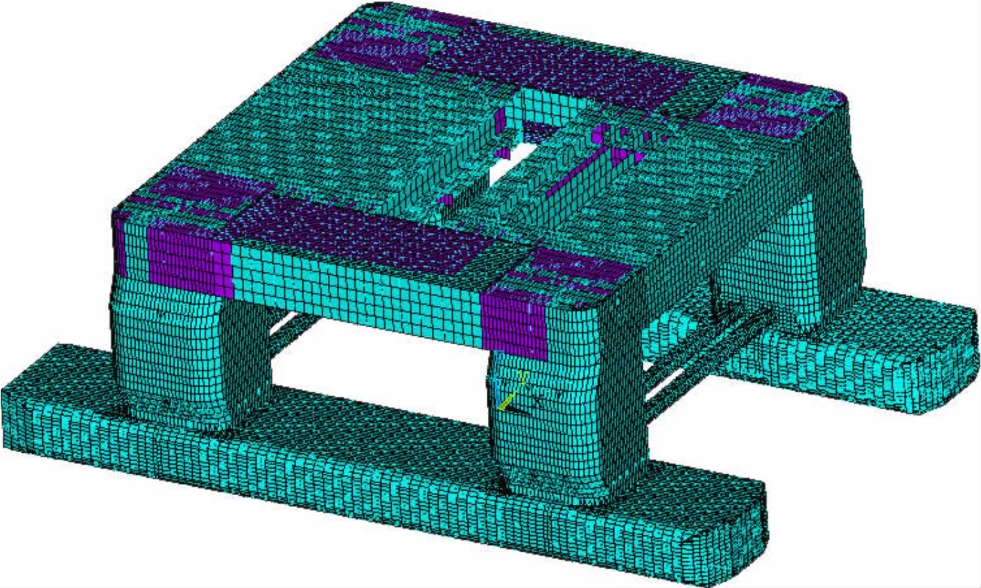
Fig.4 Nonlinear finite element model developed for of the object semisubmersible platform
4 Numerical simulation
In this study,four cases subjected to characteristic hydrodynamic conditions have been run without giving consideration to the effect of geometric imperfection and geometric nonlinear.These conditions are horizontal brace,the longitudinal forces on pontoons and columns,torsion moment on horizontal brace and main deck structure,vertical bending moment on pontoon.The calculation of the progressive collapse of the object platform is carried out according to process for ultimate limit state assessment presented in this paper.The relationships between the section load which is normalized by maximum section load under collapse states of each type and corresponding wave amplitude are given in Fig.5 for all the four cases by the nonlinear finite element analysis on the object platform.It is observed that differences of collapse modes are evident and quite match to corresponding wave condition.Fig.6 shows the deformed shapes and von-Mises stress distributions of the platform structure at the ultimate limit state for various types of wave load.Tab.4 summarizes some ultimate features of the platform obtained by ANSYS nonlinear FEA method.
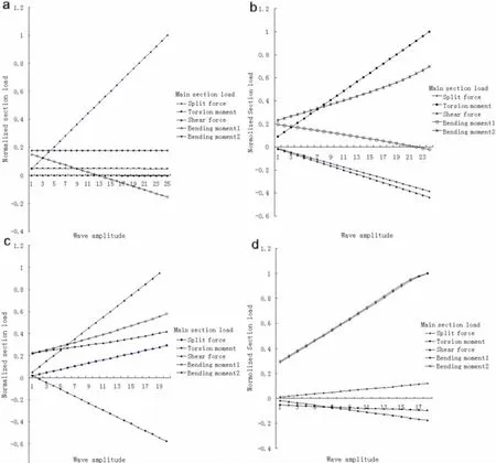
Fig.5 The ultimate limit behavior of the object platform as obtained from ANSYS nonlinear FEA(a)Split force;(b)Torsion moment;(c)Shear force;(d)Bending moment
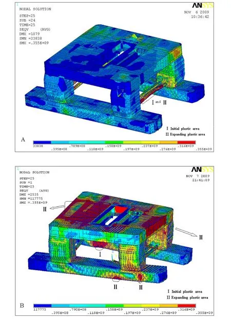
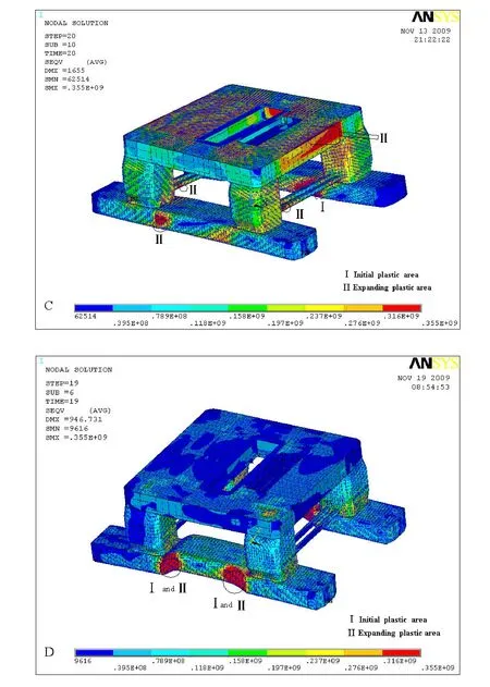
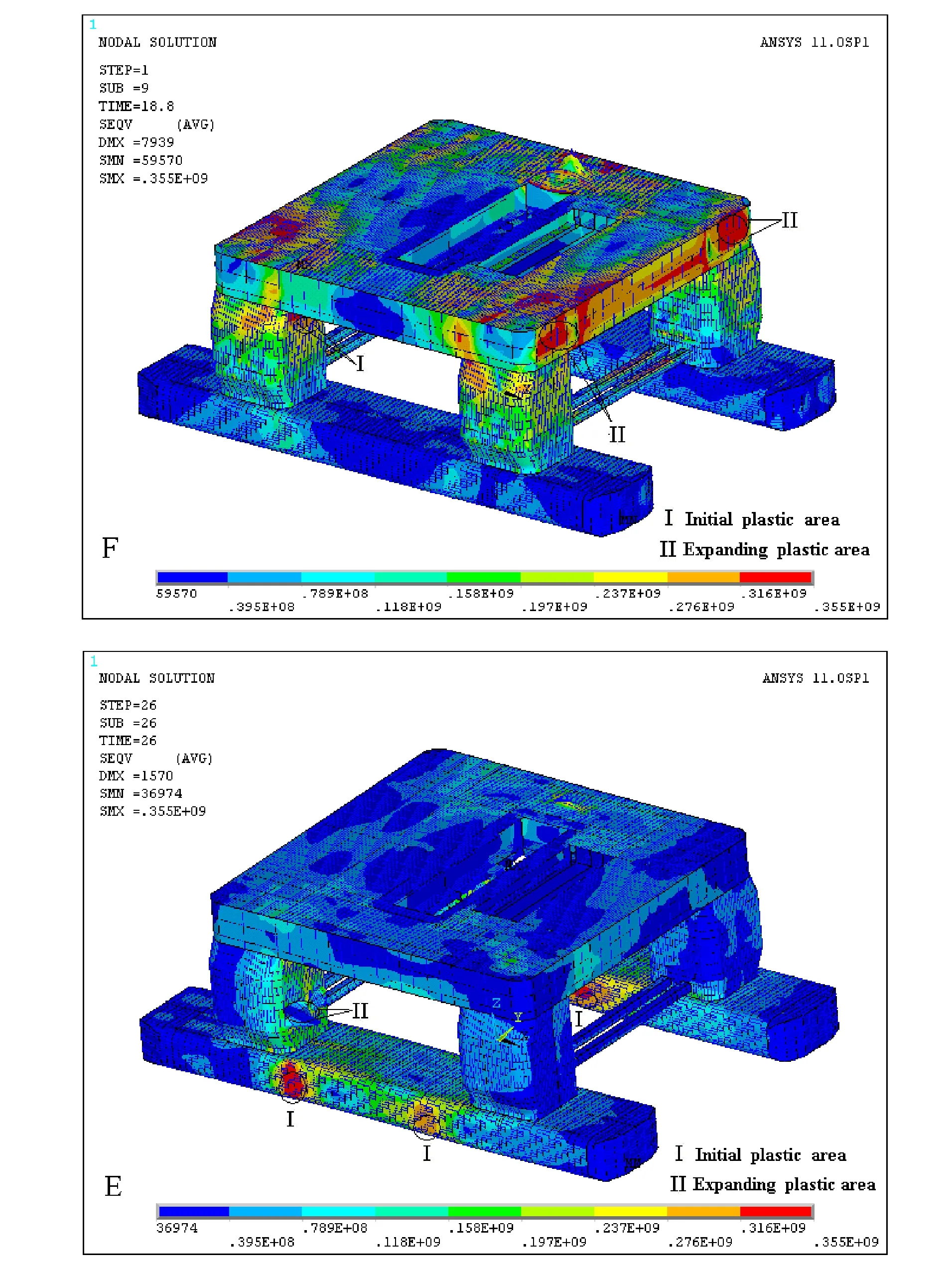
Fig.6 Deformed shapes and von-Mises stress distributions of semisubmersible platform at the ultimate limit states under regular sea wave(A)ULS of Split force;(B)ULS of Torsion moment;(C)ULS of Shear force;(D)ULS of Bending moment;(E)ULS of Longitudinal acceleration;(F)ULS of Transverse acceleration

Tab.4 Main Features of ultimate limit state
5 Discussions
5.1 Verification of simulation results
Another structural model developed by SESAM is for the purpose of a comparison.Numerical computations for comparison are carried out adopting another group of design wave parameters selected by SESAM which are close to parameters in Tab.3 with elastic material model.The distributions of maximum von Misses stress of both models are similar to those showed in Fig.6.Numerical results of the two models are listed in the same chart for compassion which can be found in Tab.5.

Tab.5 Comparison of the two finite element models
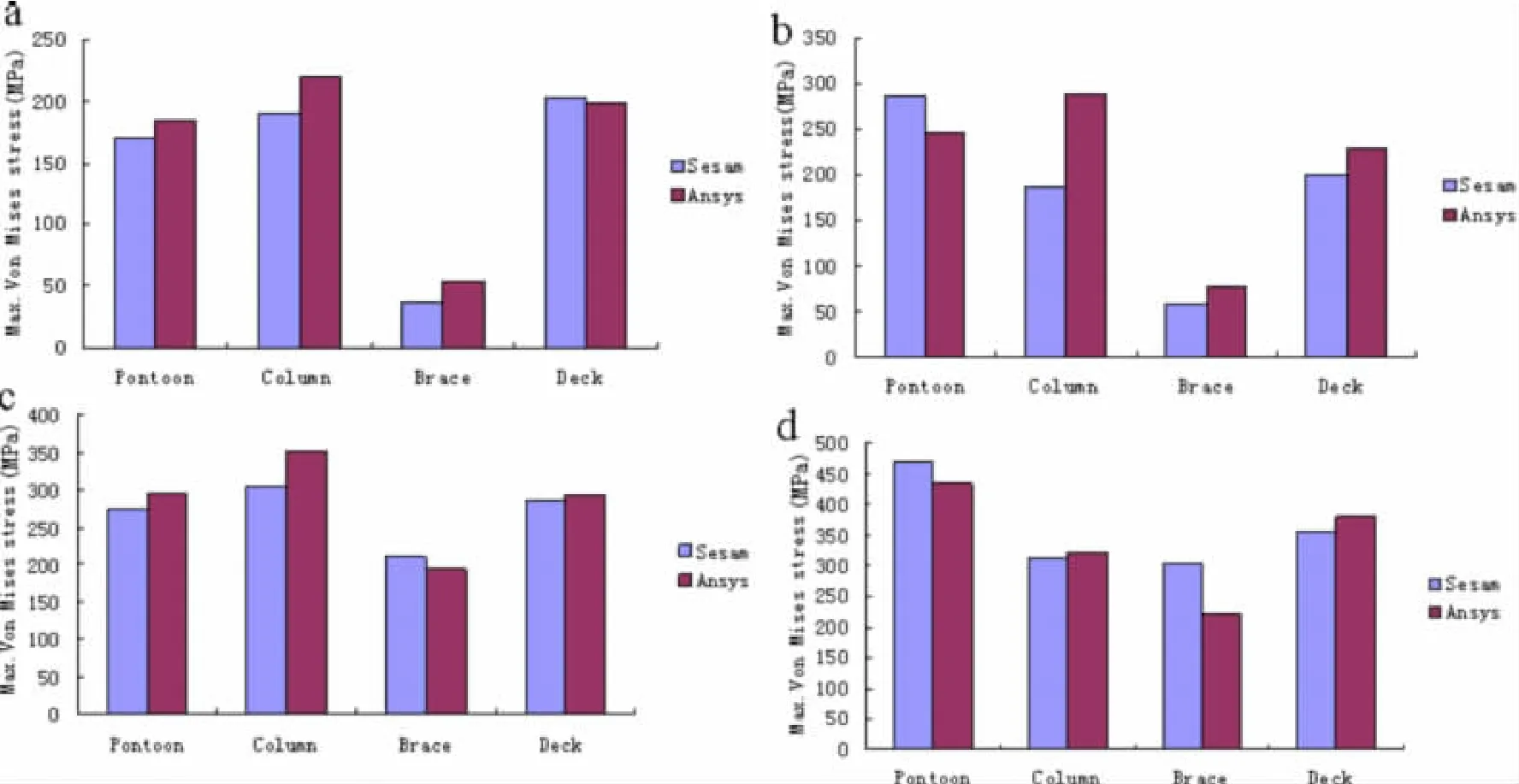
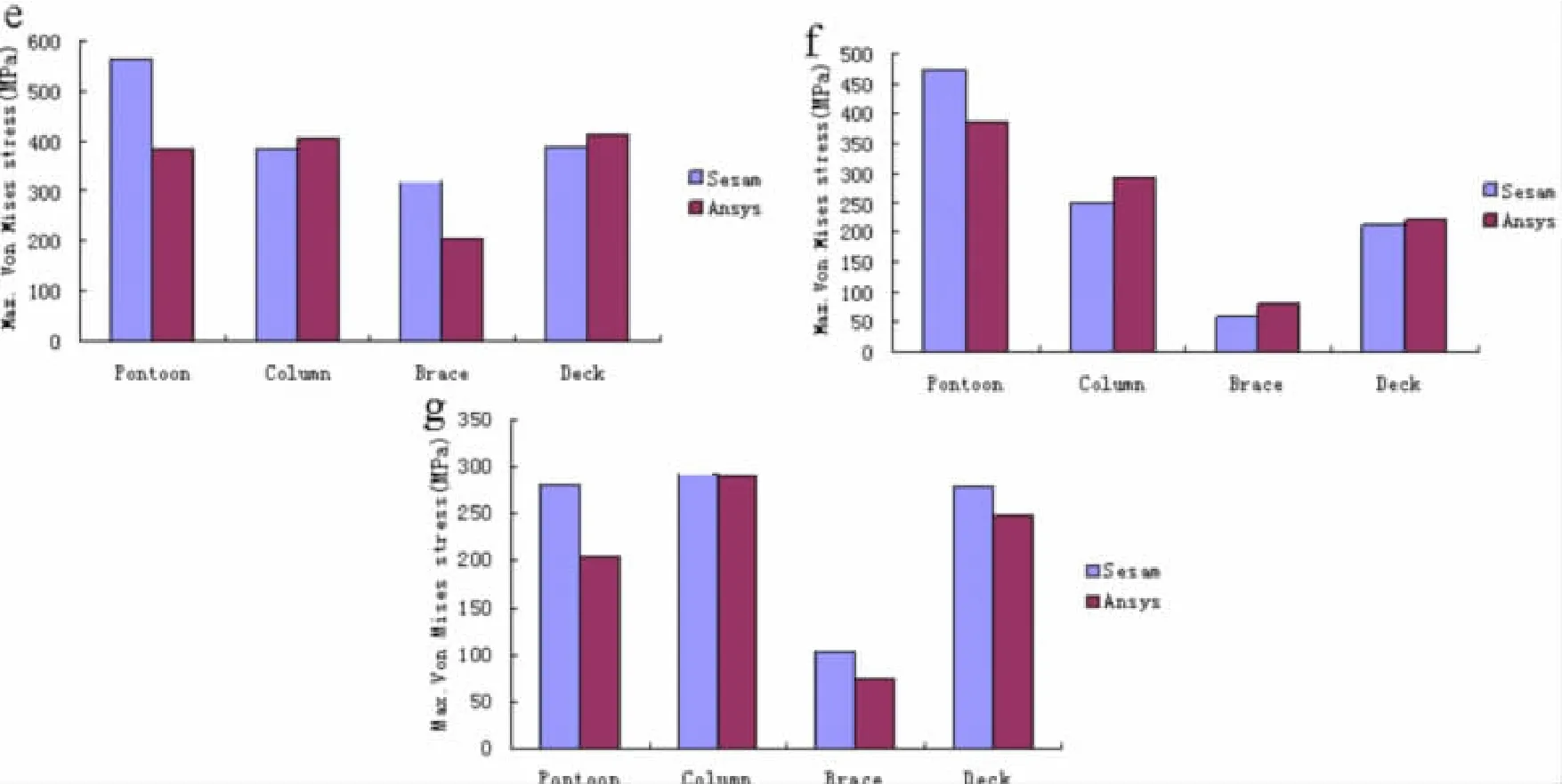
Fig.7 Numerical comparison between ANSYS and SESAM(a)Static;(b)Split force;(c)Torsion moment;(d)Shear force;(e)Bending moment;(f)Longitudinal acceleration;(g)Transverse acceleration
Among others,the results under hydrostatic and split force are very similar,and the results of longitudinal acceleration and shear force have the largest stress gap between the two models.The difference of longitudinal acceleration is around one corner of column and deck connections and is caused by finer element mesh adopted in this paper.The difference of shear force is around regions of longitudinal bulkhead of pontoon around pontoon and column connection and can be illustrated by more of model detail considered in the model built with ANSYS.Generally speaking,the results are similar and the differences can be explained as different model structure(model detail,element size,different ways of handling ballasts)and different software package to analyses(hydrodynamic and structural).
Simulation results are also validated against ABS and DNV rules.Some of response descriptions from DNV rules and ABS rules are listed in Tab.2.Theoretical response predictions from ABS rules and DNV rules can be clearly captured by the nonlinear FE analysis.It can be seen from Fig.6 that ultimate performance of each load case match corresponding response descriptions quite well.Both rules descriptions and numerical structure model developed by SESAM are used to validate the correctness of structure model developed in this paper.It can be said that the numerical results conducted in this paper are quite reasonable through these comparisons.
5.2 Discussion of simulation results
Ultimate limit behavior and performance of the object platform are showed in Fig.5 and Fig.6.It can be seen from Fig.5 that there are some relationships of main section load for each load case.These relationships can be summarized as follow:the design wave of split force can produce maximum response of split force and the other three kinds of response are not very obvious and the same to design wave of bending moment.The interaction behavior of shear force and torsion moment is quite evident and each of them can cause relative big split force and bending moment response at the same time.
The horizontal braces are the critical elements of split force case and the initial yielding places are on two outer braces which can be seen from Fig.6.Yielding expansion and stress redistribution behavior in this load case is not so evident and at ultimate limit state two outer horizontal brace are totally yielding and that lead to the final collapse of the whole platform.Initial yielding regions of torsion moment,shear force have some similarities,but their final collapse performance is different to some extent.Torsion moment have obvious expansion of plastic regions and stress redistribution behavior.The main excessive yielding regions are around column and pontoon connection and on the main deck.The structural performance of shear force is not as obvious as that of torsion moment.The response of bending moment is quite similar to that of a ship causing maximum hogging moment on the mid-pontoon.Initial yielding place is around regions of pontoon longitudinal centerline bulkhead near columns.The final collapse is caused by expanding of excessive yielding areas around initial yielding areas.
From a designer’s view,to design against split force,horizontal brace strength should be reinforced.As to load case of bending moment,if regions around columns of longitudinal centerline bulkhead of pontoon are strengthened,the vertical bending moment strength will be improved.Ultimate strength of torsion moment and shear force is relatively difficult to improve because dispersion of large plastic regions.It is suggested that concentration of detail design should be focussed on column and pontoon connection for every kind of load case.Connections of brace and column also have great importance and cannot be neglected definitely.
5.3 Ultimate limit state expression of semisubmersible platform
Tab.6lists main section loads of different load case.Fig.8 presents a comparison of main section load(or moment)of different load case of full phase angle with that of hydrostatic state.

Tab.6 Comparison of main section load of different load case with that of hydrostatic state


Fig.8 Comparison of main section load of different load case with that of hydrostatic state(a)Split force;(b)Torsion moment;(c)Shear force;(d)Bending moment
It can be seen that ultimate limit collapse of each load case is induced by main section load SF.Though Fig.5,ultimate limit strength of the target platform has close relationship of main section load of corresponding load case.Ultimate limit state expression for ultimate limit state design is recommended based on main section load SF.The object platform in hydrostatic condition induces very small section loads or moment(Fs,FL,Mt)as illustrated by Fig.8 and Tab.6.To load cases of shear force,split force and torsion moment,ultimate limit state expression can be summarized as:

where R represents ultimate limit strength of split force,torsion moment,shear force and S is corresponding main section load.Main section load of bending moment is decided by the combination effect of hydrostatic pressure and hydrodynamic pressure.The expression can be written briefly as follows:

where R is maximum vertical bending moment strength of semisubmersible platform,Sdand Ssrepresent load effect of bending moment induced by hydrodynamic pressure and hydrostatic pressure separately.
5 Conclusions
The ultimate strength of a typical drilling semisubmersible platform subjected to typical hydrodynamic loads has been investigated by nonlinear finite element method.The computer coder ANSYS is used in the analysis.Based on the limited amount of the study results obtained in the present paper,the following conclusions can be generally drawn:
(1)Ultimate limit states of semisubmersible platform are quite different from that of a hull girder of ships due to complication of structure behavior.The progressive collapse of a typical drilling semisubmersible platform is investigated using nonlinear finite element analysis with ANSYS according to global FE-analysis method for floating structure.
(2)It is not recommended to carry out ULS structural assessment of semi-submersible platform in a single model solution by DnV rules,but it is becoming available with the fast development of computer technology.The progressive collapse analysis can reflect the failures of individual structure component and their interacting effects in the best way.The object semisubmersible platform can keep integrity before the whole structure collapse for each kind of load case.The true margin of structure safety is reflected by comparison of applied wave amplitude of ULS and that of certain return period.
(3)The final collapse mode of each case has close relationship to the corresponding wave load case.The initial yielding point of split force is on horizontal brace and that of bending moment is regions of pontoon longitudinal centerline bulkhead around column.Pontoon and column connections are vulnerable regions of shear force and torsion moment.Reinforcement on these regions will improve the global strength of the object platform.
(4)Two kinds of ultimate limit state expression are recommended.The concept of these expressions can really give helps to deepen understanding on ultimate limit state behavior of semisubmersible platform.
(5)Although the numerical results in this paper are quite limited,the results of the nonlinear element analysis in the present paper can serve as a benchmark reference to the theoretical predictions of semisubmersible platform based on ABS rules and DNV rules.
[1]Amlashi H K,Moan T.Ultimate strength analysis of a bulk carrier hull girder under alternatehold loading condition-A case study-Part 1:Nonlinear finite element modeling and ultimate hull girder capacity[J].Marine Structure,2008,21:327-352.
[2]Amlashi H K,Moan T.Ultimate strength analysis of a bulk carrier hull girder under alternate hold loading condition Part 2:Stress distribution in the double bottom and simplified approaches[J].Marine Structure,2009,22:522-544.
[3]ANSYS.User’s manual(version 10.0)[K].Houston:Swanson Analysis Systems Inc.,2007.
[4]American Bureau of Shipping(ABS)Rules for building and classing mobile offshore drilling units MODU_Part_3[S].2008.
[5]Det Norske Veritas classification recommended practice for column-stabilised units(dnv-rp-c103)[R].2005.
[6]He Fuzhi,Wan Zhengquan.A simplified progressive collapse analysis of ultimate longitudinal strength of ship structures[J].Journal of Ship Mechanics,2001,5(5):21-35.
[7]Li Runpei,Wang Zhinong.Strength analysis of offshore platform[M].Shanghai:Publish of Jiao Tong University,1992.(in Chinese)
[8]Liu Haixia,Xiao Xi.The wave load calculation in the analysis of structure strength of a semisubmersible[J].Chinese Offshore Platform,2003,18(2):1-4.(in Chinese)
[9]Liu Gan,Zheng Yunlon,Zhao Deyou,Liang Yuanhua.Fatigue strength analysis of BINGO9000 semisubmersible drilling rig[J].Journal of Ship Mechanics,2002,6(2):54-63.
[10]Paik J K,Kim B J,Seo J K.Methods for ultimate limit state assessment of ships and ship-shaped offshore structures,Part I:unstiffened plates[J].Ocean Eng,2008,35:261-270.
[11]Paik J K,Kim B J,Seo J K.Methods for ultimate limit state assessment of ships and ship-shaped offshore structures,Part II:stiffened panels[J].Ocean Eng,2008,35:271-280.
[12]Paik J K,Kim B J,Seo J K.Methods for ultimate limit state assessment of ships and ship-shaped offshore structures,Part III:hull girders[J].Ocean Eng,2008,35:281-286.
[13]Faltinsen O M.Sea load on ships and offshore structure[M].Cambridge:Cambridge University Press,1990.
[14]Lee Yongwon,Incecik Atilla,Chan Hoisang.Prediction of global loads and structural response analysis on a muti-purpose semi-submersible[C].Proceedings of the International Conference on Offshore Mechanics and Arctic Engineering-OMAE,2005,1(A):3-13.
[15]Qi Enrong,Cui Weicheng.Nonlinear finite element analysis of ultimate strength of damaged ship hulls[J].Journal of Ship Mechanics,2005,9(5):83-91.
[16]Zhang Jianbo,Zeng Changke,Xiao Xi.Ultimate strength analysis of semisubmersible platform[J].Chinese Offshore Platform,2005,20(3):19-22.(in Chinese)
[17]Zhu Yanrong.Wave mechanics for ocean engineering[M].Tianjin:publish of Tianjin University,1991.(in Chinese)
[18]Wang Yanying,Li Fang.Calculation of motion response for floating structure in waves[J].Journal of Hydrodynamics,1995,10(6):571-580.(in Chinese)
- 船舶力学的其它文章
- Parametric Influence Analyses for Umbilical Installation in Deepwater
- Hydrodynamic Performance Analysis and Verification of Transverse Thrusters
- Improving of RSM-FORM and Application to Reliability Calculation of Ring-stiffened Cylindrical Shell
- Parameters Optimization of the Dynamic Absorber to Control the Axial Vibration of Marine Shafting System
- Anechoic Effect of Coating Covered on Target Submerged in Typical Shallow-water Waveguides
- 《船舶力学》稿约须知

