
EXPERIMENTAL STUDY OF CONDENSATION HEAT TRANSFER CHARACTERISTICS OF HORIZONTAL TUBE BUNDLES IN VACUUM STATES*
2012-08-22 08:31:49CHENGShenSUNFengzhongSHIYuetao
水动力学研究与进展 B辑 2012年4期
CHENG Shen, SUN Feng-zhong, SHI Yue-tao
School of Energy Source and Power Engineering, Shandong University, Jinan 250061, China, E-mail: seanwalker1982@hotmail.com
(Received May 9, 2012, Revised July 12, 2012)
EXPERIMENTAL STUDY OF CONDENSATION HEAT TRANSFER CHARACTERISTICS OF HORIZONTAL TUBE BUNDLES IN VACUUM STATES*
CHENG Shen, SUN Feng-zhong, SHI Yue-tao
School of Energy Source and Power Engineering, Shandong University, Jinan 250061, China, E-mail: seanwalker1982@hotmail.com
(Received May 9, 2012, Revised July 12, 2012)
To develop an excellent heat transfer element under the vacuum condition, experiments about the heat transfer performance of horizontal tube bundles of different materials under various vacuum conditions were carried out, including the stainless steel tube, the brass tube, the Ni-based implanted steel tube and the ion implanted brass tube. The relative trends show that the condensation heat transfer coefficient and the overall heat transfer coefficient of bundles of four materials all increase with the vacuum degree, especially, those of the Ni-based implanted steel tube and the ion implanted brass tube. Under a high vacuum condition (0.07 MPa), the condensation heat transfer coefficient of the Ni-based implanted steel tube bundle is about 1.4 times of that of the stainless steel tube bundle, the condensation heat transfer coefficient of the ion implanted brass tube bundle is found to be about 1.3 times of that of the common brass tube bundle. Therefore, according to the condensation heat transfer characteristics studied under high vacuum conditions, it is believed that a dropwise condensation is partly achieved on the surface of these two implanted tube bundles, and the ion implantation is shown to be an effective method to achieve the dropwise condensation. Based on this study, it is believed that the Ni-based steel tube may replace the brass tube, which is more expensive as a heat transfer component.
vacuum, heat transfer characteristics, condensation heat transfer coefficient, dropwise condensation
Introduction
In the industrial system, many kinds of heat exchange equipment work under vacuum conditions, and their operation capacities affect greatly the whole productive process, for instance, the working of the condenser and the low pressure heater of the regenerative system. In this paper, experiments are designed to choose a high-efficiency heat transfer element under the vacuum condition.
The steam condensation, as a typical heat transfer process, takes place on the surface of the tube bundles, and it theoretically includes the filmwise condensation and the dropwise condensation. The condensation heat transfer coefficient of the filmwise condensation,which is more common in the heat exchange equipment of industry, is about one order magnitude (even more) lower than that of the dropwise condensation[1], which is considered as a highly efficient approach of heat transfer. If the dropwise condensation is proved to be feasible in industry, in other words, to be realizable on the surface of tube bundles used as heat transfer elements during production processes, a remarkable reduction of the heat exchange area and the energy consumption can be achieved.
Many studies[2-11]were devoted to the dropwise condensation for enhancing the condensation heat transfer coefficient of tubes. The most representative work published by Kananeh team demonstrated that a stable dropwise condensation was obtained on stainless steel tubes implanted with ion doses. The measured heat transfer coefficient for the dropwise condensation was found to be larger by a factor of about 3 compared with the filmwise condensation values calculated from the corrected Nusselt’s film theory and could be enhanced by increasing the ion dose. A rising steam pressure has a positive effect on the dropwisecondensation by lowering the interfacial resistance of the heat and mass transfers at the liquid-vapor interface as well as the surface tension of the condensate[2]. However, the experiments were usually carried out for a single tube under the atmospheric pressure. The heat transfer properties of horizontal tube bundles in a vacuum state were rarely studied, but those conditions are prevalent in industrial applications, like the condenser of turbines in a power plant. This paper focuses on the heat transfer performance of the stainless steel tube bundle, the brass tube bundle, the Ni-based implanted steel tube[10,11]bundle and the ion implanted brass tube bundle. Experiments are designed to find the influencing factors of their overall heat transfer coefficients and the condensation heat transfer coefficients under various vacuum conditions and at various Reynolds number Re values. Through the comparison of their heat transfer characteristics, it is indicated that the Ni-based implanted steel tube bundle and the ion implanted brass tube bundles are recommendable for extensive applications.
1. Experimental apparatus and procedures
1.1 Experimental apparatus
The experiment system is designed in the light of the turbine condenser and based on the similarity theory (as shown in Fig.1).

Fig.1 Flow chart of the experiment
In this experiment, the steam is generated by an electrical boiler with the maximum vapor pressure of 0.4 MPa, and the feed water is the purified water filtered by a tertiary filter. The circulating water comes directly from the tap water as used in daily life. The accuracy and the range of the main measuring instruments in this experiment are as follows:
(1) Vacuum pump: with an ultimate vacuum of 0.06 Pa, the vacuum state is established and maintained in the experimental section.
(2) Circulating pump: with a lift of 40 m, the flow of the circulating water is maintained in a certain Reynolds number range in the experiment.
(3) Platinum Resistance Temperature Detector (Pt RTD): using PT100, with sufficient sensitivity to measure the steam inlet temperature, the condensation temperature and the inlet/outlet temperature of the circulating water.
(4) HP data acquisition system: for timely detecting the temperature change during the experiment, the electrical signals from Pt RTDs are collected and converted into the output temperature signals by two HP data acquisition devices, and the datum from every single temperature measuring point can be recorded within 0.1 s, the systematic uncertainty caused by working condition variations can be effectively avoided this way.
(5) Vacuum meter: with a range of –0.1 MPa-0 MPa and an accuracy of 0.01 MPa, the vacuum is measured in the experimental section.
(6) Pressure gauge: with a range of 0.1 MPa-0.5 MPa and an accuracy of 0.01 MPa, the pressure of the steam inlet is measured.
(7) Rotary flowmeter: to measure the circulating water flow in order to calculate the flow velocity (also the Re value), with an accuracy of 1.5%, a working pressure of 0.6 Mpa and a measuring range of 7 m³/h -15 m³/h.
(8) Electronic platform scale: with a division value of 10 g and a maximum range of 30 kg, the condensed water is weighed in each experiment. Afterwards the heat transfer loss and the reliability of the experiment can be determined by the enthalpy drop.

Fig.2 Schematic diagram of the experimental section
Figure 2 is a schematic diagram of the devices in the experimental section, where the tube bundles are laid horizontally at the bottom. Four test sections with respective kinds of bundles are prepared to investigate different tubes for the comparative test, the same specifications of the tubes include section of φ 0.019 m×0.0015 m, L=0.375m , n=18, and the effective heat transfer length of 0.329 m. The tube bundles are in a staggered way laid out as an equilateral triangle with the transverse pitch of 0.025 m. To guarantee the reliability of the experiment results, the section box and the tube sheets are covered by thermal insulating materials. During the experiment process, the steam from the inlet flows across the tube bundle, and the flow can be controlled with a valve. The cooling water is kept at a relatively stable temperature and is maintained under a constant pressure with a valve in the circulating water inlet, the water flow can be measured by the rotary flowmeter The section is held airtight and every junction and measuring hole are airproofed while the whole experiment is performed in a vacuum state established by the vacuum pump.
1.2 Experimental procedures
The experiment mainly concerns with the heat transfer characteristics affected by the vacuum and the Re value. The procedures are as follows:
(1) With the tertiary filter to supply the purified water to the electric boiler, the boiler prepares the steam for the experiment.
(2) The circulating pump is switched on, the circulating valve is slowly released to a certain opening, while the water flow rate is monitored till a stable value is obtained.
(3) The steam valve is released to a certain opening, to preheat the pipeline and the experimental section.
(4) The steam valve is shut off, and the vacuum pump is turned on to establish the vacuum for the experiment.
(5) The steam valve is slowly released and the vacuum valve is simultaneously adjusted to maintain the vacuum established in Step (4).
(6) The steam temperature is monitored by the data acquisition system, as it is continuously stable for 5 min, this temperature is recorded together with the water level indicated by the level gauge.
(7) The steam temperature is recorded for 8 min, and then the condensed water is discharged till the water line reaches the foregoing level.
(8) The steam valve is shut off and the condensed water is weighed on the accurate electronic platform scale, thus a test is completed for one condition.
(9) Change the vacuum in the experimental section, and repeat Steps (4)-(8).
Change the water flow rate and repeat the above steps to obtain the heat transfer characteristics with respect to various Re values.
2. Heat transfer caculation
A Wilson plot technique is used to obtain the steam side heat transfer coefficientoα. The princeples and advantages of the Wilson plot technique are well documented in Ref.[12]. A brief description of its implementation is given as follows.
Since the steam side temperature is basically constant, the logarithmic mean temperature difference Δtmis not affected by the relative flow direction (the cross flow). Therefore, the overall heat transfer coefficient Uois calculated by
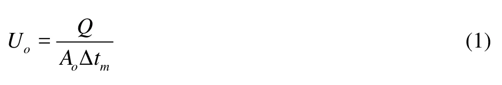
where Q is the heat transfer rate, the outside surface areaoA is used as the reference area. In the calculation ofmtΔ, the saturated temperature of the condensing steam and the inlet and outlet temperatures of the circulating water are used.
The total thermal resistanceis related to the separate thermal resistances by the following equation
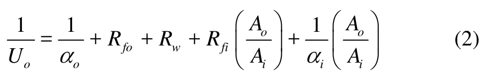
whereiA is inner surface area,fiR,foR is inner and outside fouling resistance,wR is the thermal resistance of tube wall. To obtain condensation heat transfer coefficientoα from Eq.(2) with high reliability, the water side heat transfer coefficientiα must be determined as accurately as possible. Basically, the steam heat transfer coefficient is normally higher (or much higher) than the water side heat transfer coefficient. According to the Nusselt theory,
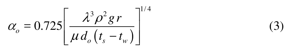
where r is the latent heat of steam, λ is the thermal conductivity of film, ρ is the density of film, g is the gravitational acceleration and μis the liquid dynamic viscosity. Evidently, if the steam pressure is kept stable, the condensation heat transfer coefficient will be constant. Thus, Eq.(2) can be re-
written as
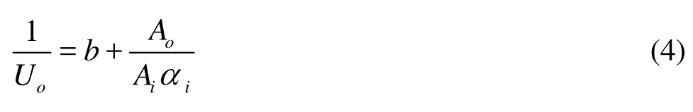
The intercept b consists of the tube wall resistance, the fouling resistances, and the steam side thermal resistance, which is kept constant for purpose of the Wilson plot.
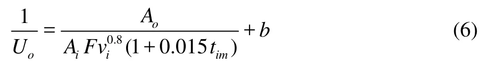
According to different correlations available to calculate the water side heat transfer coefficients, under the fully developed turbulent condition, in which the whole experiment is performed (the Re varying from 8×10³to 3×10⁴),iα is proportional to the 0.8 power of circulating water velocityiv. When the flow rate changes, the mean temperature of the waterimt changes accordingly, the impact caused by the temperature can be modified by a correction factor (1+0.015tim)[13], therefore,

where F is a proportional factor. The total thermal resistance can be calculated as
The slope k is defined as k=Ao/AiF, the linear relation betweenis as shown in Fig.3.
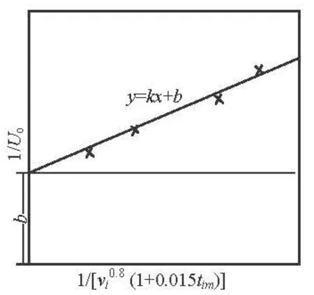
Fig.3 Linear relation betweenand [(1+ 0.015tim)]-1
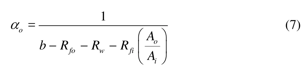
According to Eq.(2), the condensation heat transfer coefficientoα can be calculated by where Rw=do/2λwln(do/di), diis inner diameter and dois outside diameter, λwis the thermal conductivity of tube wall.Rfo=0.0001m2K·W-1, and Rfi=0.0002m2K·W-1[14].
3. Experimental results and analyses
The experiments are conducted under Re values varied from 8×10³to 3×10⁴, which are lower than that in the practical engineering. However, a fully developed turbulent flow condition is already reached, that is why the results can be used to investigate the condensation under vacuum conditions. The experimental vacuum value σ is 0.02 MPa, 0.03 MPa, 0.04 MPa, 0.05 MPa, 0.06 MPa and 0.07 MPa, corresponding to the actual vacuum of a turbine condenser.
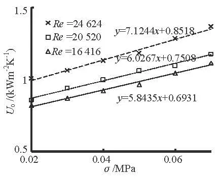
Fig.4 The relation betweenoU and the vacuum for stainless steel tube bundle
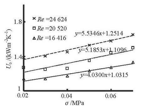
Fig.5 The relation betweenoU and the vacuum for brass tube bundle
3.1 Vertical comparison
Figures 4-7, respectively, show the relations between the overall heat transfer coefficientsoU and the vacuum for four different kinds of tube bundles under three typical Re values: 24 624, 20 520 and 16 416 (the circulating water flow rates: 1.04 m/s, 0.86 m/s and 0.69 m/s).
It is clearly indicated that no matter which kind of bundle is mounted,oU is enhanced with the in-crease of the vacuum degree and the Re value. Moreover, it is demonstrated by the slopes that the impact caused by the vacuum onoU would be greater with the increase of the Re value, more conspicuous in the trend for the Ni-based implanted steel tube bundle and the ion implanted brass tube bundle.
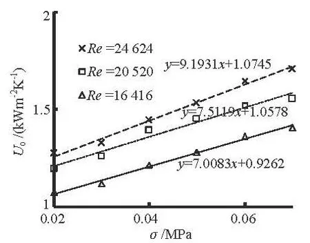
Fig.6 The relation betweenoU and the vacuum for Ni-based implanted steel tube bundle
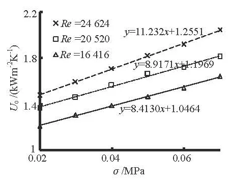
Fig.7 The relation betweenoU and the vacuum for ion implanted brass tube bundle
3.2 Horizontal comparison
The relations between the condensation heat transfer coefficientoα and the vacuum, and those between the overall heat transfer coefficientoU and the vacuum of tube bundles under a constant Re value are shown in Figs.8-11.
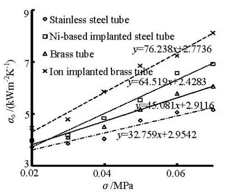
Fig.8 The relation betweenoα and the vacuum
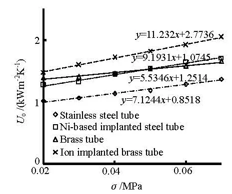
Fig.9 The relation betweenoU and the vacuum at =Re 24 624
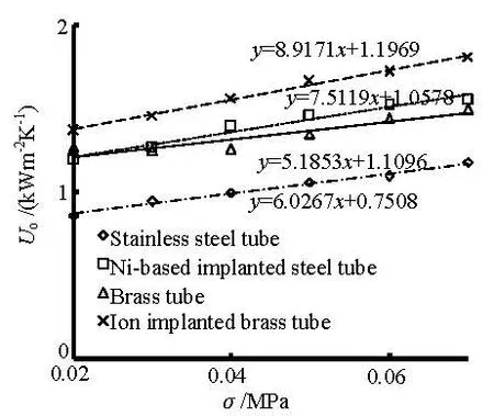
Fig.10 The relation betweenoU and the vacuum at =Re 20 520

Fig.11 The relation betweenoU and the vacuum at =Re 16 416
These figures show that bothoα andoU increase with the increase of the vacuum degree under a constant Re value. Furthermore, the Ni-based implanted steel tube and the ion implanted brass tube show more steep increase trend than the other two tubes.
As is shown in Fig.8,oα is enhanced by 82% with the vacuum degree increasing from 0.02 MPa to 0.07 MPa for the ion implanted brass tube bundle, whileoα of the Ni-based implanted steel tube bundle increases by 75% with the same vacuum range. Likewise, the increasing rates for the brass tubebundle and the stainless steel bundle are 49% and 38%. Comparing Figs.9-11, it is distinctly suggested that the vacuum has a greater impact on the condensation heat transfer coefficient than on the overall heat transfer coefficient. According to Fig.9, for the Re value of 24 624,oU for the ion implanted brass tube bundle is enhanced by 39% with the vacuum degree increasing from 0.02MPa to 0.07MPa, whileoU increases by 34% with the same vacuum range for the Ni-based implanted steel tube bundle. From the scopes in Figs.9-11, it can be seen that the vacuum effect is also reduced as the Re value is decreased.
Consider individually the relations.oα andoU for the Ni-based implanted steel tube are close to or lower than those for the brass tube under the vacuum of 0.02 MPa, however, with the increase of the vacuum degree up to 0.07 MPa, the condensation heat transfer coefficientoα of the Ni-based implanted steel tube evidently catches up and becomes higher (as clearly shown in Fig.8), which leads to a higheroU than that of the brass tube. Therefore, compared with the brass tube, the Ni-based implanted steel tube performs better in heat transfer characteristics under high vacuum conditions.
3.3 Theoretical analysis
The fact that the condensation heat transfer is enhanced with the increase of the vacuum degree can be explained as follows:
(1) As the vacuum degree increases, the steam flows more evenly across the tube bundle, the heat exchange on the surface of the tube bundle improves accordingly. The faster the steam flows, the more scouring to the drop or to the film on the surface will occur, therefore, the condensate will be detached from the bundle as soon as possible, so the heat exchanging area is enlarged and the heat transfer is enhanced accordingly. In addition, the vacuum is created by the suction effect of the vacuum pump, accompanied with the rise of the pump output, the non-condensed gas is continuously exhausted, as a result, the additional heat resistance by the accumulation of the non-condensed gas is reduced, which would lead to the condensation heat transfer improvement.
(2) By comparison, the condensation heat transfer coefficients of the Ni-based implanted steel tube bundle and the ion implanted brass tube bundle can reach 2 or 3 times of those of the other two kinds of bundles, which shows that a partly dropwise condensation is probably achieved on the surfaces of these two kinds of bundles in the experiment. It is generally agreed that the heat transfer coefficient of the dropwise condensation is 10 times higher than that of the filmwise condensation. It is demonstrated in this paper that a partly dropwise condensation is achieved in the experiment as an imperfect dropwise condensation.
(3) Due to the better heat transfer performance of the Ni-based implanted steel tube bundle and the ion implanted brass tube bundle, much more amount of new steam flows into the experimental section, where the steam temperature is higher than that of the other two kinds of bundles. The higher temperature is beneficial to the condensation on the heat transfer surface. Therefore, compared with the stainless steel tube bundle and the brass tube bundle, the vacuum has relatively more significant influence on the heat transfer characteristics of the Ni-based implanted steel tube bundle and the ion implanted brass tube bundle with the increase of the Re value.
4. Conclusions
Through this experiment, it is found that for the stainless steel tube bundle, the brass tube bundle, the Ni-based implanted steel tube bundle or the ion implanted brass tube bundle, their overall heat transfer coefficients all increase with the increase of the vacuum degree, and also with the increase of the Re value. Furthermore, the steam flows faster with the increase of the vacuum degree, therefore, with a decreasing interfacial heat resistance and the lower surface energy and then an enhanced dropwise condensation heat transfer coefficient, that is to say, the vacuum condition has a greater impact on the heat transfer performance for the latter two kinds of bundles than for the former two, which means that with a fixed vacuum and Re value condition, the ion implanted brass tube bundle performs best, while the stainless steel tube bundle performs the poorest in this experiment.
Moreover, it is concluded that the heat transfer coefficients of the Ni-based implanted steel tube bundle are better than those of the brass tube bundle under high vacuum conditions, which indicates that the Ni-based implanted steel tube, as an upgrade version of the common stainless steel tube by implantation, has better corrosion resistance[15], lower production cost and better heat transfer characteristics than the brass tube. That is to say, as the implantation technology develops, the Ni-based implanted steel tube may completely replace the brass tube to be applied in the condenser in industry.
[1] MA X., ROSE J. W. and XU D. et al. Advances in dropwise condensation heat transfer: Chinese research[J]. Chemical Engineering Journal, 2000, 78(2-3): 87-93.
[2] KANANEH A. B., RAUSCH M. H. and FRÖBA A. P. et al. Experimental study of dropwise condensation on plasma-ion implanted stainless steel tubes[J]. International Journal of Heat and Mass Transfer, 2006, 49(25-26): 5018-5026.
[3] RAUSCH M. H., LEIPERTZ A. and FRÖBA A. P. Dropwise condensation of steam on ion implanted titanium surfaces[J]. International Journal of Heat and Mass Transfer, 2010, 53(1-3): 423-430.
[4] MA X.-H., ZHOU X.-D. and ZHONG L. et al. Condensation heat transfer enhancement in the presence of noncondensable gas using the interfacial effect of dropwise condensation[J]. International Journal of Heat and Mass Transfer, 2008, 51(7-8): 1728-1737
[5] GOKHALE S. J., PLAWSKY J. L. and WAYNER Jr P. C. Experimental investigation of contact angle, curvature, and contact line motion in dropwise condensation and evaporation[J]. Journal of Colloid and Interface Science, 2003, 259(2): 354-366.
[6] TARTARINI P., CORTICELLI M. A. and TAROZZI L. Dropwise cooling: Experimental tests by infrared thermography and numerical simulations[J]. Applied Thermal Engineering, 2009, 29(7): 1391-1397.
[7] VEMURI S., KIM K. J. An experimental and theoretical study on the concept of dropwise condensation[J]. International Journal of Heat and Mass Transfer, 2006, 49(3-4): 649-657.
[8] GUILIZZONI M., SOTGIA G. Experimental analysis on the shape and evaporation of water drops on high effusivity, microfinned surfaces[J]. Experimental Thermal and Fluid Science, 2010, 34(1): 93-103.
[9] BOUGRIOU C., BESSAIH R. Determination of apparent heat transfer coefficient by condensation in an industrial finned-tube heat exchanger: Prediction[J]. Applied Thermal Engineering, 2005, 25(11-12): 1863-1870.
[10] SUN Feng-zhong, ZHANG Ming-yuan and HUANG Xin-yuan. Experimental research of intensifying heat transfer on Ni-based implanted longitudinal finned tube[J]. Journal of Hydrodynamics, Ser. B, 2002, 17(4): 467-471.
[11] WANG Nai-hua, LI Shu-ying. Experimental research of realizing dropwise condensation on Ni-based implanted tubes surface[J]. Power Engineering, 2002, 22(3): 1804-1807(in Chinese).
[12] ROSE J. W. Heat-transfer coefficients, Wilson plots and accuracy of thermal measurements[J]. Experimental Thermal and Fluid Science, 2004, 28(2-3): 77-86.
[13] HOLMAN J. P. Heat transfer[M]. New York: McGraw-Hill, 2002.
[14] MÜLLER-STEINHAGEN H., MALAYERI M. R. and WATKINSON A. P. Fouling of heat exchangers-new approaches to solve an old problem[J]. Heat Transfer Engineering, 2005, 26(1): 1-4.
[15] GAO M., SUN F. and SHI Y. et al. Experimental research and theoretical analysis of anti-fouling characteristics on the surface of Ni-based implanted tube[J]. International Communications in Heat and Mass Transfer, 2006, 33(9): 1115-1121.
10.1016/S1001-6058(11)60286-2
* Project supported by the National Key Basic Research Program of China (973 Program, Grant No. 2011CB710702). Biography: CHENG Shen (1982-), Male, Ph. D. Candidate
SUN Feng-zhong,
E-mail: sfzh@sdu.edu.cn

- 水动力学研究与进展 B辑的其它文章
- THE NATURAL CONVECTION OF AQUIFERS WITH CONSTANT HEAT SOURCES AND ITS INFLUENCE ON TEMPERATURE FIELDS*
- EFFECT OF ESCAPE DEVICE FOR SUBMERGED FLOATING TUNNEL (SFT) ON HYDRODYNAMIC LOADS APPLIED TO SFT*
- EXPERIMENTAL STUDY OF AIRFLOW INDUCED BY PUMPING TESTS IN UNCONFINED AQUIFER WITH LOW-PERMEABILITY CAP*
- SIMULATION OF HYDRAULIC TRANSIENTS IN HYDROPOWER SYSTEMS USING THE 1-D-3-D COUPLING APPROACH*
- TOTAL PHOSPHORUS RELEASE FROM BOTTOM SEDIMENTS IN FLOWING WATER*
- EFFECTS OF UNDERSCOUR DEPTH AND HORIZONTAL SPACING BETWEEN TWO BED PROTECTION BLOCKS ON STABILITY OF FRONTAL BLOCK*