
Reactive Distillation for Producing n-Butyl Acetate: Experiment and Simulation
2012-03-22 10:11T
T
anIA d NW U H uYia(n田x i晖an)g
1 ,( 吴H
U燕A翔N)G2, *Z hixian (黄智贤)2, QIU Ting (邱挺)2, WANG Xiaoda (王晓达)21 College of Chemistry and Chemical Engineering, Yantai University, Yantai 264005, China
2 College of Chemistry and Chemical Engineering, Fuzhou University, Fuzhou 350002, China
1 INTRODUCTION
The conception of Reactive Distillation (RD) was firstly reported by Backhaus in 1921 [1], and has received more and more attentions, especially for the equilibrium-limited reversible reactions. RD had became an attractive unit operation due to the following reasons: (1) enhancing conversion and selectivity for equilibrium reaction, (2) breaking the composition of azeotropic mixtures, (3) reducing the energy consumption and the number of equipments [2-4].
n-Butyl acetate (n-BuAc) is one of the most common solvents, which is used in lacquer and coating manufacture and other branches in large quantity. The consumption ofn-BuAc grows in the last decade because it is of low toxic and environment-friendly compared with other esters [5].n-BuAc is synthesized through esterification by acetic acid (HAc) andn-butanol (n-BuOH) with acid catalyst. Because the reaction is reversible, the conversion ofn-BuOH is limited by the chemical equilibrium. Removing the products during the reacting is beneficial for enhancing the conversion. Thus, an integrated RD process is desirable.
The information aboutn-BuAc synthesis in a RD column is plentiful in the literature. In China, Liao and Tong [6] studied the synthesis ofn-BuAc by RD using the cation exchange resin as the catalyst primeval, and the conversion of HAc could reach 94%. Meanwhile the conversion of HAc andn-BuOH were all above 96% at the optimized condition in their study. Hanikaet al. [7] studied then-BuAc synthesis through RD in a packed column experimentally, and the computer simulation was performed to evaluate the experimental data.But three columns were used to obtain high purity(>99%)n-BuAc product, and the RD column had 50 theoretical stages, while then-BuAc product (>96%)was obtained in this paper using one RD column only with 26 theoretical stages. The high purity product(>99%) could be obtained by simple separation from the raw product in this paper, which decreased the energy obviously. Based on the computer simulation, Steinigeweg and Gmehling [8] carried out the pilot plant test to study the RD process for producingn-BuAc using the strongly acidic ion exchange resin (Amberlyst-15)as the catalyst, and both the thermodynamic and the kinetic aspects of the system were investigated. While they used the RD column with 30 theoretical stages,the product purity could come to 96%. Gangadwalaet al. [9] explored various RD configurations for the production ofn-BuAc in order to eliminate the by-product di-butyl ether, but they did not validate the model results experimentally. Jimenez and Costa-Lopez [10]using methyl acetate andn-BuOH producedn-BuAc and methanol, while three columns were used to obtain high purityn-BuAc product, and the RD column had 43 theoretical stages. Qiuet al. [11] investigated the kinetic model of the esterification reaction byn-BuOH and HAc catalyzed by Amberlyst 36 Wet, and the Langmuir-Hinshelwood-Hougen-Watson (LHHW)model was proposed to describe the reaction.
The aim of this study was to investigate the performance of RD for the production ofn-BuAc from HAc andn-BuOH in more detail. Experimental studies were performed in our lab and simulation studies were carried out using the ASPEN PLUS simulator.Emphasis was placed on analyzing the effects of key parameters such as the height of rectifying, reaction and stripping sections, and also the feed location, on the conversion ofn-BuOH andn-BuAc purity.
2 EXPERIMENTAL MATERIAL AND THE ANALYSIS METHORD
HAc (purity >99%, by mass) was supplied by Shenbo Chemical CO., andn-BuOH (>99.8%) was supplied by Merck. The catalyst used in the present experiment was cation exchange resin Amberlyst 36 Wet, produced by Rohm and Haas, and the parameters were given in Table 1.
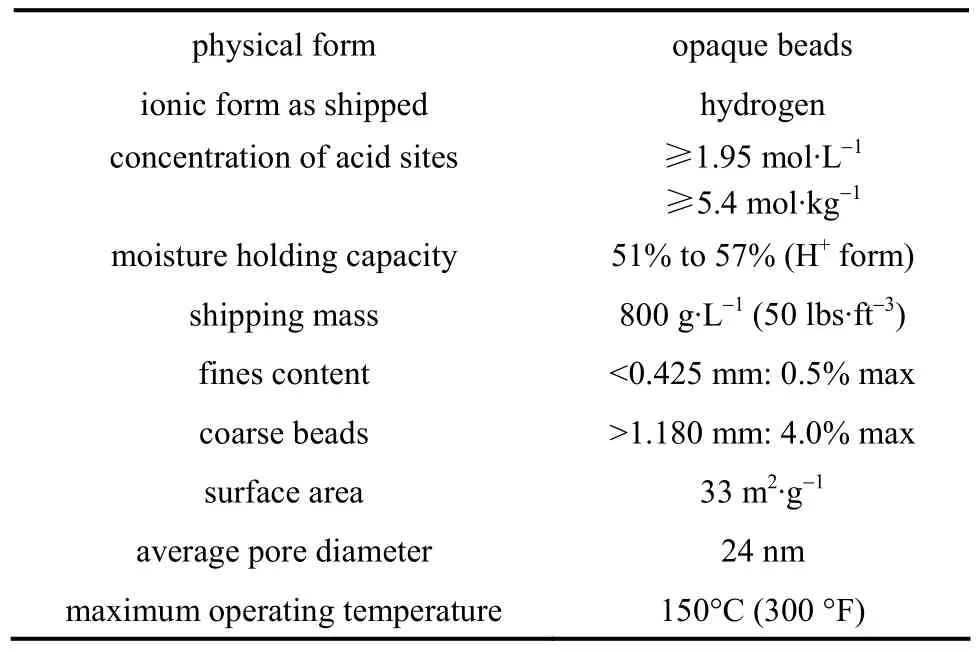
Table 1 Physical properties of Amberlyst 36 Wet
Both titration and gas chromatography were used for the analysis of the reaction mixtures. The gas chromatograph (Varian CP-3900, USA) equipped with a hydrogen flame detector. A CP-8907 column was used with nitrogen as the carrier gas at a flow rate of 1 ml·min-1. Injector and detector temperature were 523.15 K and 573.15 K, respectively. The water in organic phase was measured by means of the Karl-Fischer instrument. The concentration of free HAc was determined through titrating with standard 0.1 mol·L-1sodium hydroxide solution, and phenolphthalein was used as the indicator.
3 KINETIC MODEL
In this work, the Langmuir-Hinshelwood- Hougen-Watson (LHHW) kinetic model was used to describe the reaction occurring in the RD column. The reaction of synthesisn-BuAc from HAc andn-BuOH in the reactive zone can be written as follows:

The rate of reaction for the LHHW model can be written as follows:
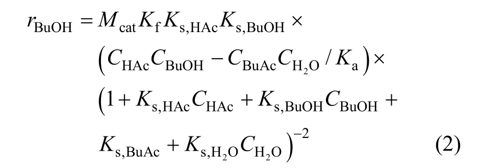
whereris the reaction rate (mol·s-1);Ciis the concentration (mol·L-1);Mcatis the catalyst mass (g);Kfis the reaction rate constant (mol·g-1·s-1);KsandKaare chemical reaction equilibrium constant and adsorption equilibrium constant, respectively. All of the parametersKare expressed as

All the parameters of the LHHW kinetic model were taken from the Ref. [11] for the esterification catalyzed by Amberlyst 36 Wet ion-exchange resin.The average relative error was less than 2%, and the kinetic parameters were given in Table 2.
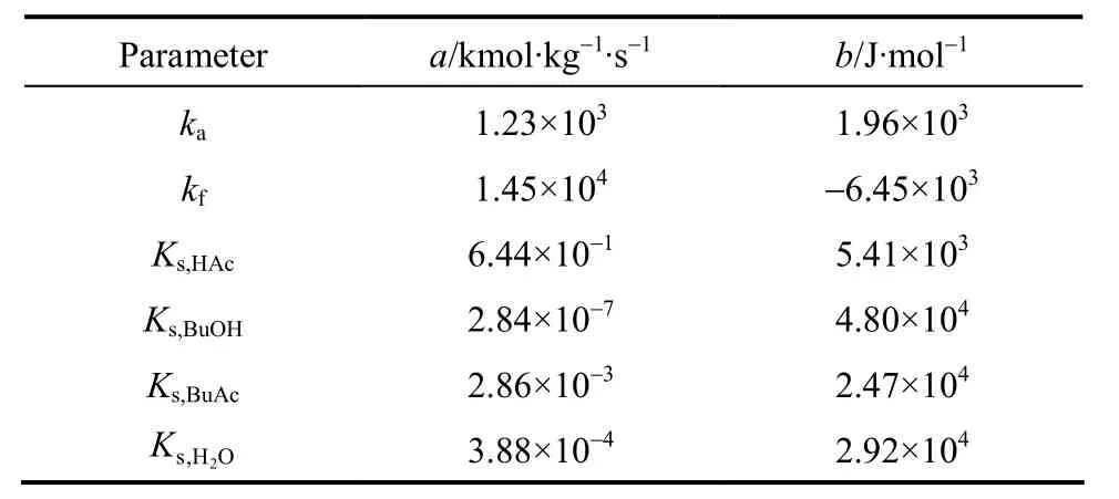
Table 2 Parameters of the LHHW kinetic model for n-BuAc reaction system [11]
4 REACTIVE DISTILLATION EXPERIMENT AND SIMULATION
4.1 Experimental setup
A RD column containing solid catalyst was used for the synthesis ofn-BuAc. The strong cation exchange resin (Amberlyst 36 Wet) was used as the catalyst. The experimental setup was given in Fig. 1.The setup included a RD column with internal diameter of 32 mm in addition to a fixed-bed reactor with internal diameter of 20 mm with the height of 600 mm for fulfilling part of the load of reaction. The rectifying section and the stripping section of the RD column were packed with bulk θ packing (Ф2.5 mm) while catalyst-bundles containing cation exchange resin catalyst were packed in the middle of the column as the reaction zones [12]. The height of the rectifying section, the reaction section, and the stripping section were 550 mm, 1050 mm, and 600 mm, respectively. In order to describe the RD column separation efficiency quantitatively, the number of theoretical stages (TS) of RD column was estimated by using the Fenske method through separating a mixture of ethanol and isopropyl alcohol [13]. The results indicated that the separation efficiencies of rectifying section, reactive section, and stripping section were equivalent to 8, 6,and 9 theoretical stages, respectively. The temperature was measured at eight points in the column while the samples were taken from top, bottom and along the column (as shown in Fig. 1). The theoretical stages were numbered from the top of the column to the column bottom (reboiler), and the relationship between sampling and the number of theoretical stage were shown in Table 3.
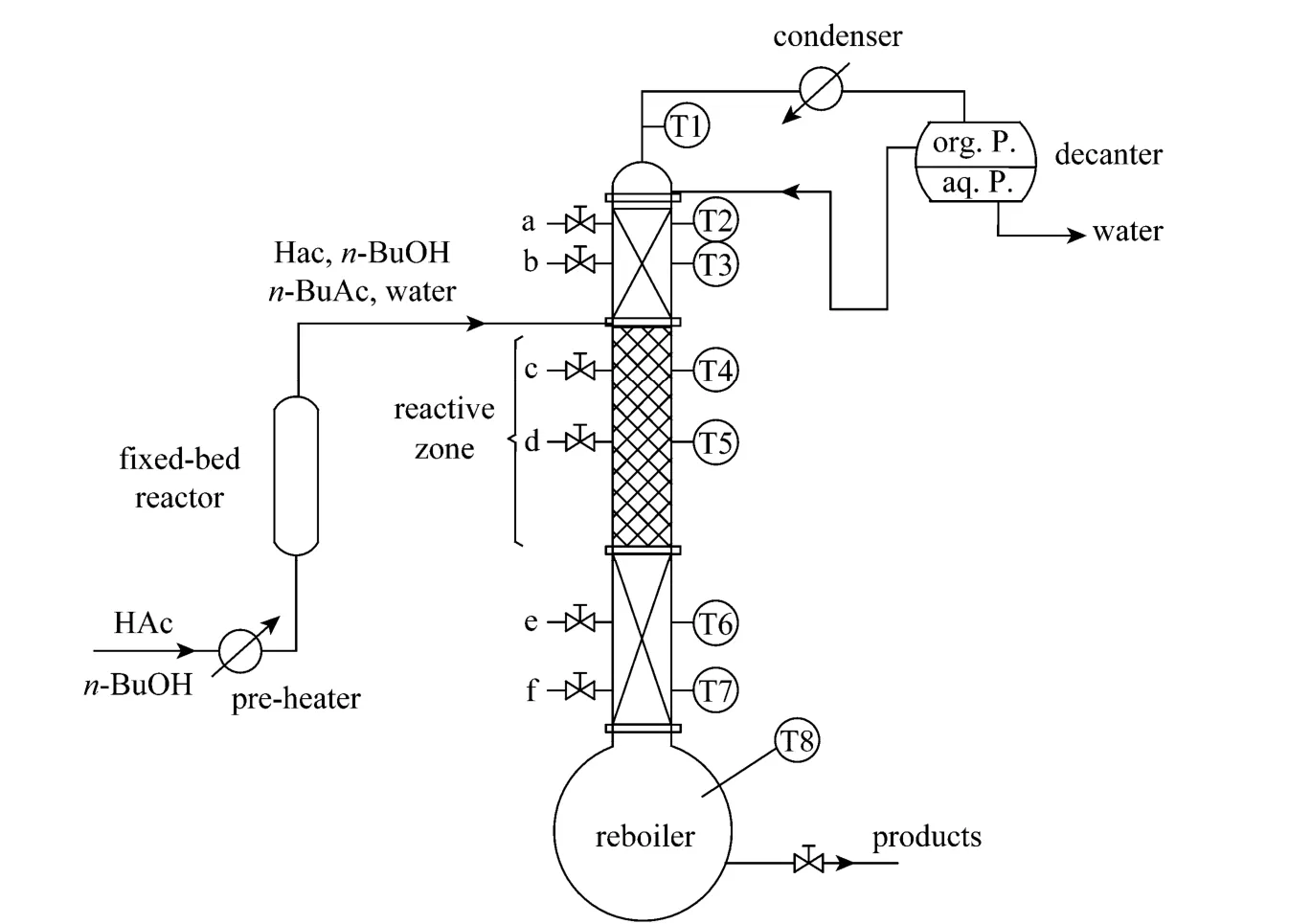
Figure 1 Reactive distillation experimental setup
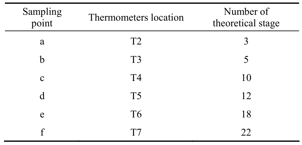
Table 3 The relationship of sampling and thermometers location with number of theoretical stage
During the production ofn-BuAc by this setup,the equimolarn-BuOH-HAc mixture was fed to the first reactor which was packed with ion exchange resin.The temperature in the fixed-bed was maintained at 358.15K. The effluent from the fixed-bed reactor,which almost achieves the chemical equilibrium, entered the RD column above the reactive zone.n-BuAc,whose boiling point was the highest in this system,was withdrawn from the bottom of the column. The overhead distillate was mainlyn-BuOH, HAc, water,and a small amount ofn-BuAc. The overhead vapor was condensed and cooled to liquid at room temperature at first and then introduced to a decanter for phase separation. While the organic phase was completely refluxed back to the column, the aqueous phase which might still contain small amount of the organic compounds (i.e.,n-BuAc, unreactedn-BuOH and HAc)was withdrawn from the system.
4.2 Modeling and simulation
The RD was a complex process, which contains not only the mass transfer process but also the separation and reaction processes. In this paper, simulation of the synthesis ofn-BuAc in a RD column was carried out by using Aspen Plus 11.1. The equilibrium stage model is often applied with great success for the simulation of RD column [14]. Therefore, the RADFRAC module, based on the rigorous equilibrium stage model containing the mass balance, phase equilibrium, summation and energy balance (MESH) equations, was used to describe the multistage vapor-liquid separation in the RD. To simplify the calculation, the low pressure drop along the column (about 2 kPa) was neglected according to some researches [15, 16], for the whole equipment was supposed to operate at atmospheric pressure.
The selection of the physical property method was very important due to the highly non-ideal nature of the quaternary system, and the phase equilibrium of this system was complex because of the existence of azeotropes. Because of the non-ideal vapor-liquid equilibrium (VLE) and possible vapor-liquid-liquid equilibrium (VLLE) for the quaternary system, the UNIQUAC activity coefficient model was adopted [9],and the model equation came from the Aspen Plus user manual 11.1. The Hayden-O’Conell model with association parameters was used to account for the dimerization and trimerization of HAc in the vapor phase [17]. The Aspen Plus built-in association parameters were used to compute the fugacity coefficients.The binary interaction parameters of the UNIQUAC model came from the built-in Aspen Plus Databanks and Ref. [17]. The azeotropes for the four components system [HAc-(n-BuOH)-(n-BuAc)-H2O] calculated at the atmospheric pressure were listed in Table 3. From Table 4, the calculated azeotropic composition and temperature were compared with the literature values,and the maximal error was less than 1%, showing the selection of the thermodynamic model was reliable.
Since the available built-in reaction kinetic model in Aspen Plus 11.1 was power law and defined on the basis of mass or mole fraction, the reaction kinetics model forn-BuAc system based on LHHW [Eq. (2)]was incorporated into the process simulator using an additional subroutine written in FORTRAN, and the different catalyst concentrations and the efficiency of the catalyst-bundle [18] in the RD column were considered. The simulation was run and fitted to the available experimental data by adjusting the Murphree stage efficiency (from 0.5 to 0.8), and the value of which is reasonable [15].

Table 4 The compositions and temperatures of the azeotropes at atmospheric pressure

24 1-8 stage 9-14 stage 15-24 stage 9th stage 27.5 (9-14 stages) 1∶1 0.2348
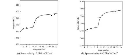
Figure 2 Temperature profile in the RD column simulation; ■ experimental
According to the experimental setup, the theoretical stages were numbered from the column to the column bottom (reboiler). The process parameters of the experiment and the specification of the RD column for process simulation were listed in Table 5.
4.3 Model validation
In order to check whether the model was suitable for simulating the RD column, the model was used to predict the temperature distribution and vapor composition along the RD column, and the predictions were compared with the experimental data obtained in the present study. The temperature and concentration profiles obtained from the experiment and simulation results were shown in Figs. 2 and 3. The experimental values were all came from the average value of three experiments and the relative errors were all less than 2.0%.
Figure 2 demonstrated the calculated temperature profile was similar to the experimental values and the maximum relative error was 1.1%, which was acceptable. From Fig. 3, it can be seen that the vapor compositions in 6 sampling points were in good agreement with the simulation results. The errors mainly came from the equilibrium stage model not accounting for transport phenomena. The conversion ofn-BuOH as defined as was calculated to compare the performance of the RD.
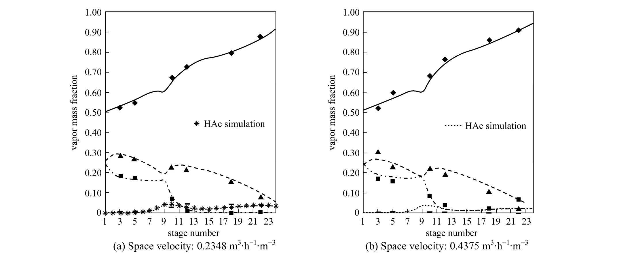
Figure 3 Experimental and predicted concentration profiles in the sampling location▲ BuOH experimental; BuOH simulation; ◆ BuAc experimental; ■ H2O experimental; H2O simulation; BuAc simulation; HAc experimental

Experimental and simulation results at different space velocity and HAc concentration were listed in Figs. 4 and 5. The experimental values were all came from the average value of three experiments and the relative errors were all less than 1.0%. From Fig. 4,n-BuOH conversion reduced gradually along with the space velocity increase because of the limit of the reactive section capacity.n-BuOH conversion reduced gradually along with the reducing of the HAc concentration. It was evident that the experimental data agreed very well with the results of the numerical model, and the equilibrium stage model could describe well the RD column profiles.

Figure 4 Experimental and simulation results at different space velocity◆ experimental; simulation

Figure 5 Experimental and simulation results at different HAc concentration◆ experimental; simulation
5 DISCUSSION
Due to the constraints and limitations in the experimental study, some of the important RD design parameters could not be studied experimentally. The important design variables considered include the number of rectifying, reaction and stripping stages and the feed stage location. So a series of analysis were conducted to determine the effects of the design variables on conversion ofn-BuOH and the purity ofn-BuAc.The conditions of the base case simulation study were the same as shown in Table 5. From the base case, a series of sensitivity studies were performed to study the RD column performances.
5.1 Number of reaction stages
Increasing the number of reaction stages was not always a better option because that will affect the column separation performance, thereby changing compositions in the reactive zone. For equilibrium limited systems, increasing the number of reaction stages will lead to the enhancement of temperature and concentration which would favor the reversion reaction, causing the product decomposition [19, 20]. Fig. 6 shows the influence of the number of reaction stages on the RD column performance. All other design and operating variables such as the number of rectifying,stripping stages and feed conditions were kept at the values of the standard condition and the mixture which was close to chemical equilibrium being from the fixed-bed reactor is still fed at the top of the reaction section. The simulated results shown that by using more reaction stages both the conversion ofn-BuOH and the purity ofn-BuAc were increased, and the heat duty of the reboiler also increased. This was to be expected as the reactive zone in the column could be analogous to the series of reactors. The number of reactors in the series increased as the height of the reactive zone increased and therefore that provided sufficient residence time for higher conversion. The number of reaction stages of 8 was used as one of the column configurations for the following simulations.
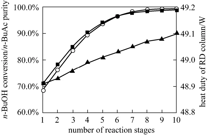
Figure 6 Effects of reaction stages on n-BuOH conversion and n-BuAc purity○ n-BuAc purity; ■ n-BuOH conversion; ▲ heat duty
5.2 Number of rectifying stages
The rectification section of the RD column forn-BuAc synthesis should remove light components from the reaction zone, and recycle the unreacted reactants back to the reaction section in the RD column.The effects of the number of the rectifying stages on the purity ofn-BuAc, the conversion ofn-BuOH and the heat duty of the reboiler were demonstrated in Fig. 7.It was found that the purity ofn-BuAc, the conversion ofn-BuOH and the heat duty of the reboiler increased slightly with the increase of the number of rectification stages from 2 to 11 stages. This could be explained by the fact that with the increase of the rectifying stages,water and the lightest component were more removed from the reaction section, decreasing the concentration of water in the reaction zone. This caused the equilibrium of reaction (1) to shift forward and thus, the conversion ofn-BuOH and the purity ofn-BuAc became higher,both reached at 96.5% and 96.4%, respectively. It could be concluded that the contribution of the increase of rectifying stages to the column performance became progressively small and therefore the number of rectifying stages of 5 was used as the column configurations for the following simulations.

Figure 7 Effects of rectifying stages on n-BuOH conversion and n-BuAc purity○ n-BuAc purity; ■ n-BuOH conversion; ▲ heat duty
5.3 Number of stripping stages
In the RD, the number of stripping stages should be adjusted to achieve a satisfactory separation. The main function of the stripping section was to maintain favorable reaction conditions by removingn-BuAc from the reactive zone, purifying then-BuAc product in the residue, and minimizing the loss ofn-BuOH in the product ofn-BuAc. It could be seen from Fig. 8 that then-BuOH conversion,n-BuAc purity and the heat duty of the reboiler increased as the number of stripping stages was increasing from 2 to 15 stages.Increasing the number of stripping stages decreased the concentration ofn-BuAc in the reaction zone,shifting the equilibrium of the etherification forwardn-BuAc. Therefore, the optimum configuration was 13 stripping stages.
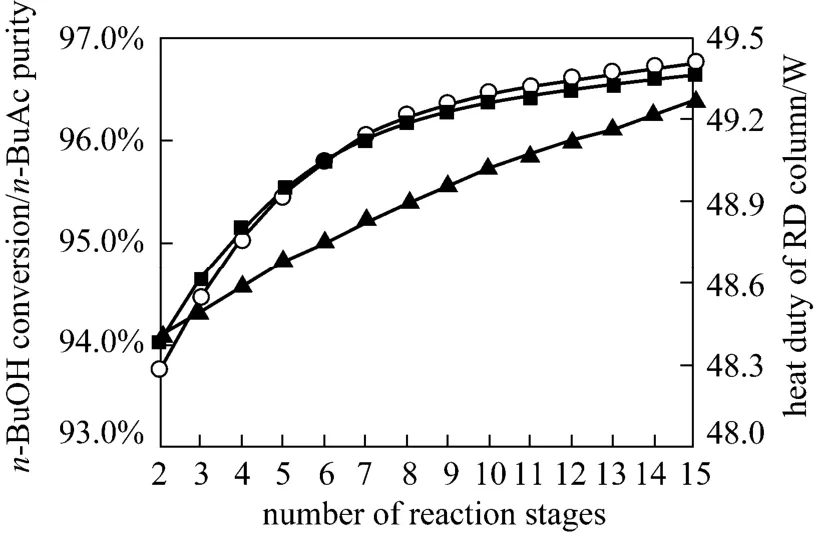
Figure 8 Effects of stripping stages on n-BuOH conversion and n-BuAc purity○ n-BuAc purity; ■ n-BuOH conversion; ▲ heat duty
5.4 Feed stage location
The RD column could be treated as a tubular reactorcascaded with separation units, while the reactive zone of a RD column could be viewed as a cascade-type two-phase reactor with the reaction temperature determined from the bubble-point temperature of the tray liquid phase composition. The composition and temperature profiles could affect the performance of the reactive zone, and the feed tray location appear to be one of the most important variables for these profiles redistribution [21, 22]. The right choice for feed location ensured high concentrations of reactants in the reactive zone. Fig. 9 presented the effects of the feed location onn-BuOH conversion,n-BuAc purity and the heat duty of the reboiler. It was found that feeding equilibrium reaction mixture at the 5th TS offered the highest conversion ofn-BuOH (96.83%) and the highest purity ofn-BuAc (96.71%).

Table 6 Compare of the experiment and simulation value of n-BuOH conversion and n-BuAc purity
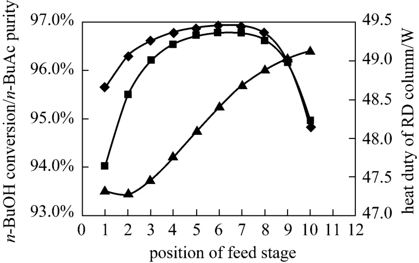
Figure 9 Effects of feed stage on n-BuOH conversion and n-BuAc purity○ n-BuAc purity; ■ n-BuOH conversion; ▲ heat duty
5.5 Optimization
According to the simulation results, the RD experimental setup was changed to 5 rectifying stages, 8 reaction stages and 13 stripping stages based on the experimental setup, and the location of the feed stage was the 6th stage. Therefore, the experiment 1#, 2#and simulation results are obtained as shown in Table 6.n-BuOH conversion andn-BuAc purity are all greater than 96%, all greater than the results of Refs. [6, 7].
6 CONCLUSIONS
Experimental setup was performed in order to develop a reliable framework for simulating RD that was capable of modeling then-BuAc synthesis relatively accurately. The simulation results shown that the experimental data agreed with the simulation results well. The equilibrium stage model could describe the column profiles quantitatively. The effects of some important process parameters were investigated with the aid of simulation studies and the optimal parameters were obtained: the optimal design variables for the RD were 5 rectifying stages, 8 reaction stages and 13 stripping stages, and the best feed location was the 6th theoretical stages. According to the simulation results,the RD column was changed to 5 rectifying stages, 8 reaction stages and 13 stripping stages based on the experimental setup.n-BuOH conversion andn-BuAc purity were all greater than 96% at this condition.
1 Backhaus, A., “Continuous process for the manufacture of esters”,US Pat., 1400849 (1921).
2 Baur,R., Higler, A.P., Taylor, R., Krishna, R., “Comparison of equilibrium stage and none equilibrium stage models for reactive distillation”,Chem.Eng.J., 76 (33), 387-392 (2000).
3 Zhao, S.Y., Huang, J.Z., Wang, L.E., Huang, G.Q., “Coupled reaction/distillation process for hydrolysis of methyl acetate”,Chin.J.Chem. Eng., 18 (5), 755-760 (2010).
4 Ma, L., Zhang, Y., Yang, J.C., “Purification of lactic acid by heterogeneous catalytic distillation using ion-exchange resins”,Chin.J.Chem. Eng., 13 (1), 24-31 (2005).
5 Arpornwichanop, A., Koomsup, K., Assabumrungrat, S., “Hybrid reactive distillation systems forn-butyl acetate production from dilute acetic acid”,J.Ind.Eng.Chem., 14 (6), 796-803 (2008).
6 Liao, A.P., Tong, Z.F., “Synthesis of butyl acetate catalyzed by Amberlyst”,Chemical Reaction Engineering and Technology, 11 (4),406-408 (1995). (in Chinese)
7 Hanika, J., Kolena, J., Smejkal, Q., “Butyl acetateviareactive distillation, modelling and experiment”,Chem.Eng.Sci., 54 (21),5205-5209 (1999).
8 Steinigeweg, S., Gmehling, J., “n-Butyl acetate synthesisviareactive distillation: Thermodynamic aspects, reaction kinetics, pilot-plant experiments, and simulation studies”,Ind.Eng.Chem.Res.41 (22), 5483-5490 (2002).
9 Gangadwala, J., Radulescu, G., Kienle, A., Sundmacher, K., “Computer aided design of reactive distillation processes for the treatment of waste waters polluted with acetic acid”,Comput.Chem.Eng., 31(11), 1535-1547 (2007).
10 Jimenez, L., Costa-Lopez, J., “The production of butyl acetate and methanolviareactive and extractive distillation (II) Process modeling, dynamic simulation, and control strategy”,Ind.Eng.Chem.Res.,41 (13), 6735-6744 (2002)
11 Qiu, T., Huang, Z.X., Cheng, C.B., Wu, Y.X., “Kinetics of synthesisn-butyl acetate over cation-exchange resin catalyst”,Chemical Reaction Engineering and Technology, 25 (4), 355-359 (2009). (in Chinese)
12 Klöker, M., Kenig, E.Y., Górak, A., Markusse, A.P., Kwant, G.,Moritz, P., “Investigation of different column configurations for the ethyl acetate synthesisviareactive distillation”,Chem.Eng.Process.,43 (6), 791-801 (2004).
13 Du, Y.C., Guo, J.B., Hu, R.T., “Synthesis ofn-butyl acetate by catalytic rectification”,Petrochemical Technology, 36 (4), 349-354(2007). (in Chinese)
14 Lee, H.Y., Huang, H.P., Chen, I.L., “Control of reactive distillation process for production of ethyl acetate”,Journal of Process Control,17 (4), 363-377 (2004).
15 Zheng, Y.X., Flora, T.T.N., Garry, L.R., “Catalytic distillation: A three-phase none quilibrium model for the simulation of the aldol condensation of acetone”,Ind.Eng.Chem.Res., 40 (23), 5342-5349(2001).
16 Almeida-Rivera, C.P., Swinkels, P.L.J., Grievink, J., “Designing reactive distillation processes: Present and future”,Computers.Chem.Eng., 28 (10), 1997-2020 (2004).
17 Zeng, G.B., Li, S.J., Qian, F., “Dynamic simulation and control of acetic acid dehydration system”,Computers and Applied Chemistry,25 (5), 533-537 (2008). (in Chinese)
18 Li, C.S., Daisuke, H., Suzuki, K., “n-Butyl acetate synthesisviareactive distillation: Thermodynamic, process design”,Computers and Applied Chemistry, 24 (12), 1585-1589 (2009). (in Chinese)
19 Wu, Y.X., Wang, L.E., Zhao, Z.S., “Mass transfer model for catalyst capsule in catalytic distillation (II) Mensuration and calculation of effectiveness factor”,Journal of Chemical Industry and Engineering(China), 53 (5), 508-512 (2002). (in Chinese)
20 Subawalla, H., Fair, J.R., “Design guidelines for solid-catalyzed reactive distillation systems”,Ind.Eng.Chem.Res., 38 (10), 3696-3709(1999).
21 Bhatia, S., Mohamed, A.R., Ahmad, A.L., Chin, S.Y., “Production of isopropyl palmitate in a catalytic distillation column: Comparison between experimental and simulation studies”,Comput.Chem.Eng.,31 (10), 1187-1198 (2007).
22 Doherty, M.F., Malone, M.F., Conceptual Design of Distillation System, McGraw-Hill, New York (2001).
 Chinese Journal of Chemical Engineering2012年5期
- Chinese Journal of Chemical Engineering的其它文章
- Ammoximation of Cyclohexanone to Cyclohexanone Oxime Catalyzed by Titanium Silicalite-1 Zeolite in Three-phase System*
- Adsorption and Desorption of Praseodymium (III) from Aqueous Solution Using D72 Resin*
- Turbulent Characteristic of Liquid Around a Chain of Bubbles in Non-Newtonian Fluid*
- Isolation and Characterization of Heterotrophic Nitrifying Strain W1*
- Recovery of Tungsten (VI) from Aqueous Solutions by Complexationultrafiltration Process with the Help of Polyquaternium*
- Optimizing the Chemical Compositions of Protective Agents for Freeze-drying Bifidobacterium longum BIOMA 5920*