A desired landing points walking method enabling a planner quadruped robot to walk on rough terrain
MA Hongwen,WANG Liquan,ZHONG Zhi,YAO Shaoming
(College of Mechanical and Electrical,Harbin Engineering University,Harbin 150001,China)
Legged robots were first developed more than half a century ago.For all kinds of structures,satisfactory drivers and sensors have been designed and manufactured.However,legged robots are still not suitable for walking on rough terrain in a natural environment as human beings or other animals can do easily,the reason is that the walking pattern generation method for this kind of robot is not consummate.
ZMP is widely used to control legged robots[1],and it performs excellently in static walking conditions.Symmetrical running is a good method for dynamic feedback control[2];however, the robot using this method can hardly walking on rough terrain.Passive walking solves the problem of efficient walking[3-4],but it is unsuitable for complex feedback control.
Recently,the real-time walking pattern generator has attracted the attention of many scholars.Kajita proposed a three-dimensional linear inverted pendulum mode to generate a real-time walking pattern[5].Later,he used preview control in ZMP to generate a real-time walking pattern[6].Park used cycloid functions and 3rd order polynomial functions to generate a real-time walking pattern[7].Héliot proposed a method to synchronize the motion of a robot or another device with respect to the output signal of the sensor[8].Fukuoka proposed a CPG control method based on biological concepts for a quadruped robot to walk at medium walking speed on irregular terrain[9].Arbulu addressed the problem of generating dynamic motion for a humanoid robot between two predefined postures using ZMP preview control[10].Zonfrilli proposed a walking generator and controller based on the inverted pendulum approach with the innovative feature of fully using the double support phase for the walking generation and control[11].Kurazume proposed a methodology for generating a straight legged walking pattern for a biped robot utilizing the up-and-down motion of an upper body[12].Diedam proposed a method to generate a walking gaits online based on a linear model predictive control[13].Huang proposed a walking control method consisting of a feedforward dynamic pattern and a feedback sensory reflex[14].However,most of these methods are imperfect for enabling a multi-legged robot to walk smoothly on rough terrain.
In this paper,a walking method using desired landing points and adopting a preview controller is proposed for a point-shape-foot planner quadruped robot.It allows the robot to walk smoothly on rough terrain.In section I,the concept of the controller is briefly presented,and the details of controller,i.e.the realtime foot motion trace generator,are introduced in sections II and III.In section IV,simulations are provided to prove the correctness of this method.
1 Desired landing points
As shown in
Fig.1,while feet 2 and 4 make contact with the ground,feet 1 and 3 lift off simultaneously at the current time.At the desired time the lift-off feet,1 and 3,then touch down to the ground.The positions of desired landing points(DLP),1'and 3'are calculated before the current time according to the desired moving distance of the trunk,Ds,and the desired moving distances of feet 1 and 3.
The key of this method is the calculation of DLP for flying feet at the current time.

Fig.1 Planner quadruped robot walks using the desired landing points method
Fig.1(a)illustrates the state of current time.Fig.1(b)illustrates the state of desired time.Fig.1(c)illustrates the composition of Fig.1(a)and Fig.1(b).
Fig.2 illustrates the motion trace of one foot in the Cartesian world coordinate system.The motion trace can be separated into two parts:flying period and supporting period.The flying period can be further separated into three parts:lifting-off period,freely-flying period,and touching-down period.The characteristic of the traces in the lifting-off and touching-down periods is that they are perpendicular to the ground,which decreases the interaction between foot and ground in the lifting-off and touching-down periods.In the Cartesian trunk coordinate system,the motion trace of the foot can be shown as in Fig.3.
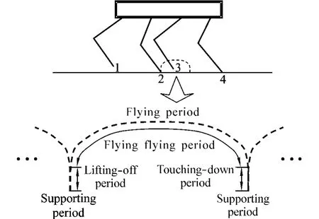
Fig.2 Motion trace of one foot in Cartesian world coordinate system
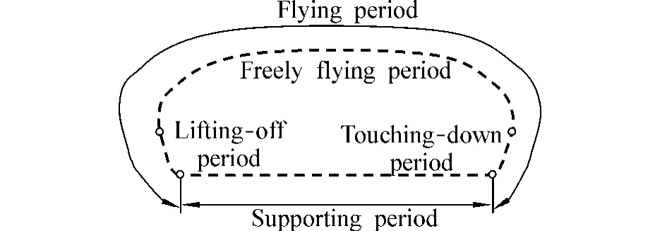
Fig.3 Motion trace of one foot in Cartesian trunk coordinate system
2 Off-line foot motion trace on plain terrain
To simplify the analysis,only transitional joints are used by all robot legs,as shown in Fig.4.

Fig.4 Planner quadruped robot with transitional joints

Fig.5 Motion trace of a foot
Suppose the trunk of the robot moves at uniform speed in the positive direction along axis x.To maintain this movement,a kind of foot motion trace is shown in Fig.5.‘t0-t7’is the flying period and‘t7-t8’is the supporting period.Among‘t0-t7’,‘t0-t1’is the lifting-off period,‘t1-t6’is the freely flying period,and‘t6-t7’is the touching-down period.
Supposing the initial speed of the trunk is v,then the initial foot speed along axis x is -v,and the initial foot speed along axis y is 0 in the trunk coordinate system.All the accelerations of one foot in each period are given in Table 1.

Table 1 Accelerations in every periods
Accelerations are described in trunk coordinate system.A is a constant determined by the maximum lifting-off height.T is the period of walking step.△t is the lifting-off period or touching-down period.Where t1-t0=t2-t1= t3-t2= t5-t4= t6-t5=t7-t6=△t,and t4-t3=T -6△t.
A walking step means a period from the lifting-off time to the touching-down time for a flying foot or a period from the touching-down time to the lifting-off time for a landing foot.The flying foot moves from its initial time,t0,and the supporting foot moves from its initial time,t7,simultaneously.
When each foot of the robot moves according to the above motion trace,the robot can walk at uniform speed on a plain terrain.
3 On-line modification of the foot motion trace
To walk on rough terrain,the morphology of the terrain ahead should be detected in advance.Many methods can be used to accomplish such a task:structure light vision,laser scanning,etc.The morphology of the ground in a world coordinate system has been measured in this paper.
3.1 Speed modification
Speed modification of the trunk is accomplished using supporting feet.Suppose the initial speed of the trunk is v,and the speed is changed to v'at the end of a walking step.The change of the speed is in uniform acceleration.The acceleration along axis x of the supporting foot is

The moving distance of the trunk is

3.2 Lifting-off height modification
To adapt the lifting-off feet to the morphology of the ground,the lifting-off height should be modified.The top of Fig.6 shows the motion trace of a lifting-off foot in a world coordinate system and the bottom of Fig.6 shows the trace in a trunk coordinate system.

Fig.6 Planner quadruped robot with transitional joints
Take both A and B in consideration,data in Table 1 are changed as shown in Table 2.△a is determinate by h in Fig.6.

Table 2 Accelerations in every Period.
3.3 Step length modification and avoidance of unsuitable landing terrain
Some terrains are unsuitable for landing,such as a slope with steep gradient,as shown in Fig.7.The initial desired landing point,A,is unsuitable for landing.

Fig.7 Planner quadruped robot with transitional joints
By setting the initial landing point as a center point,then using an interval,△d,to search the points in the range,R,as shown in Fig.7,we obtain a suitable desired landing point,B.
Step length of the robot should be modified for landing on the suitable desired landing point.The Dsin Table 2 is used to modify the step length of the flying feet.
3.4 ZMP computation
The modification of the foot motion trace obeys the ZMP rules.The ZMP can be computed by using the following equations:
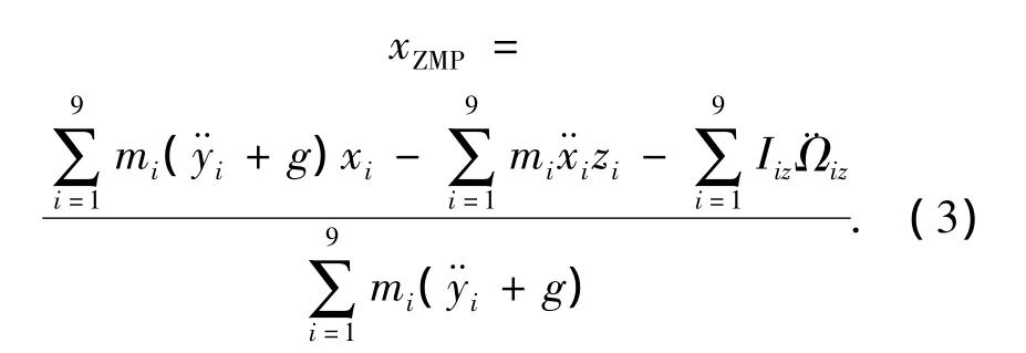
Where,miis the mass of link i,Iizis the inertial components,g is the gravitational acceleration.(xZMP,0)is the coordinate of ZMP,and(xi,yi)is the coordinate of the mass center of link i in a Cartesian world coordinate system.

Fig.8 ZMP boundary considering stability margin
To simplify the computation of ZMP,only the trunk is calculated in Eq.(3)because the mass and inertia of the trunk are much larger than those of other parts of the robot.A stability margin is adopted to prevent the overturning of the robot,as shown in Fig.8.
4 Simulation
Key parameters are given in Table 3,as shown in Fig.9.

Fig.9 Structure of a planner quadruped robot
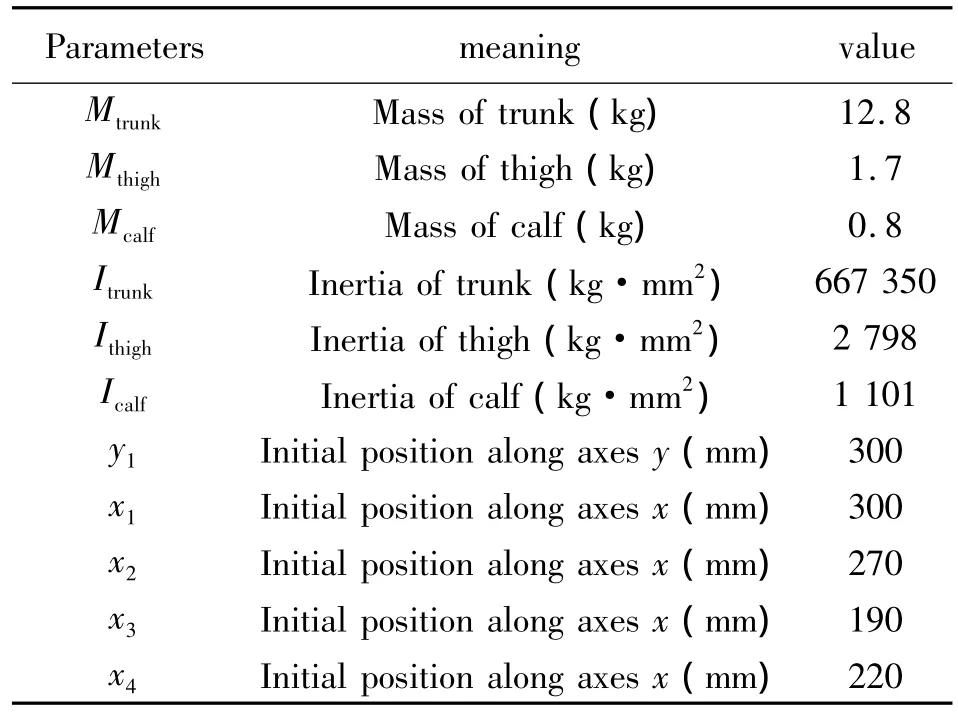
Table 3 Key parameters of planner quadruped robot
All leg joints are controlled using a simple position PID controller,as shown in Fig.10.

Fig.10 Position PID controller of a joint
All simulations are accomplished using the Adams and Simulink methods.The control code is written in SFunction.
4.1 Walking at uniform speed and variable speed on plain terrain
The top view of Fig.11 illustrates when the robot walks at uniform speed,and the bottom view of Fig.11 illustrates when the robot walks at variable speed.Fig.12 shows the walking speed of the trunk measured by the Adams method.

Fig.11 Robot walking on plain ground at uniform speed and variable speed respectively
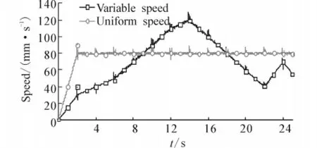
Fig.12 Trunk speed measured in Adams
4.2 Walking on rough terrain
The top view of Fig.13 illustrates when the robot walks with the modification of foot lifting-off height,and the bottom view of Fig.13 illustrates when the robot walks without the modification of foot lifting-off height.Fig.14 shows the component,z,of the trunk posture measured by the Adams method.

Fig.13 Robot walking on rough terrain with and without lifting-off height modification
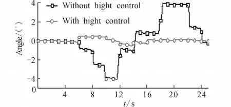
Fig.14 Trunk pitch angle measured in Adams
4.3 Avoidance of unsuitable landing terrain
Fig.15 illustrates a sequence of foot sliding when the robot lands on an unsuitable landing terrain.The upper robot and lower robot in each segment are controlled without and with avoidance control of unsuitable landing terrain respectively.At shown in Fig.15(a),the next desired landing points are calculated,which will be adjusted by the avoidance control method if they are unsuitable for landing.At shown in Fig.15(b),the feet land on an unsuitable point for the upper robot and the feet land on a proper point for the lower robot.Fig.15(c)and Fig.15(d)illustrate the sliding of the feet.
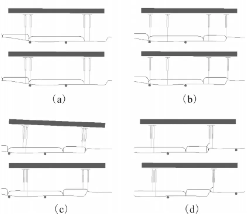
Fig.15 Avoidance of unsuitable landing terrain
5 Conclusion
A desired landing points(DLP)walking method was proposed in this paper.The characteristics of this method are summarized as follows.
1)Point-shape foot was used in the analysis.
2)Speed,lift-off height,and step length modification of foot motion trace was used to make a robot walk smoothly on rough terrain.
3)The morphology of the terrain ahead should be detected in advance to modify the foot motion trace.
The dynamics of the robot is not considered in this paper and will be covered in future analysis.
[1]VUKOBRATOVI C'M,BOROVAC B.Zero-moment pointthirty five years of its life[J].International Journal of Humanoid Robotics,2004,1(1):157-173.
[2]RAIBERT M H.Legged robot that balance[M].Cambridge,USA:Massachusetts Institute of Technology,1986.
[3]MCGEER T.Passive dynamic walking[J].International Journal of Robotics Research,1990,9(2):62-82.
[4]COLLINS S H,RUINA A L,TEDRAKE R,et al.Efficient bipedal robots based on passive-dynamic walkers[J].Sci-ence,2005,307(5712):1082-1085.
[5]KAJITA S,KANEHIRO F,KANEKO K,et al.A realtime pattern generator for biped walking[C]//Proceedings of the 2002 IEEE International Conference on Robotics and Automation.Washington,DC,USA,2002:31-37.
[6]KAJITA S,KANEHIRO F,KANEKO K,et al.Biped walking pattern generation by using preview control of zeromoment point[C]//Proceedings of the 2003 IEEE International Conference on Robotics and Automation.Taipei,China,2003:1620-1626.
[7]PARK I W,KIM J Y,OH J H.Online biped walking pattern generation for humanoid robot KHR-3(KAIST humanoid robot-3:HUBO)[C]//The 6thIEEE-RAS International Conference on Humanoid Robots.Genova,Italy,2006:398-403.
[8]HÉLIOT R,ESPIAU B.Online generation of cyclic leg trajectories synchronized with sensor measurement[J].Robotics and Autonomous Systems,2008,56(5):410-421.
[9]FUKUOKA Y,KIMURA H,COHEN A H.Adaptive dynamic walking of a quadruped robot on irregular terrain based on biological concepts[J].The International Journal of Robotics Research,2003,22(3/4):187-202.
[10]ARBULU M,YOKOI K,KHEDDAR A,et al.Dynamic acyclic motion from a planar contact-stance to another[C]//IEEE/RSJ International Conference on Intelligent Robots and System.Nice,France,2008:3440-3445.
[11]ZONFRILLI F,WOLLHERR D,NAKAMURA Y.Walking control of the humanoid UT-theta[C]//Proceedings of the 12th International Conference on Advanced Robotics.Seattle,USA,2005:698-704.
[12]KURAZUME R,TANAKA S,YAMASHITA M,et al.Straight legged walking of a biped robot[C]//2005 IEEE/RSJ International Conference on Intelligent Robots and Systems.Edmonton,Canada,2005:3095-3101.
[13]DIEDAM H,DIMITROV D,WIEBER P,et al.Online walking gait generation with adaptive foot positioning through linear model predictive control[C]//IEEE/RSJ International Conference on Intelligent Robots and Systems.Nice,France,2008:1121-1126.
[14]HUANG Q,NAKAMURA Y.Sensory reflex control for humanoid walking[J].IEEE Transactions on Robotics,2005,21(5):977-984.

