
Design of a Magneto-Electric Dipole Element for Mobile Communication Base Station Antennas
2011-06-19 06:37HangWongandKwaiManLuk
ZTE Communications 2011年2期
Hang Wong and KwaiMan Luk
(1.State Key Laboratory of Millimeter Waves(Hong Kong);
2.Department of Electronic Engineering,City University of Hong Kong)
Abstract:The magneto-electric dipole antenna is a kind of complementary antenna composed of a planar electric dipole and a shorted patch antenna.It has excellent electrical characteristics including wide impedance bandwidth,low cross-polarization,low back lobe radiation,nearly identical E-plane and H-plane patterns,stable radiation pattern,and steady antenna gain over the operating frequency range.In this paper,the basic characteristics of a linearly polarized magneto-electric dipole antenna are reviewed,and a dual-polarized antenna element based on the magneto-electric dipole is presented.The design of a conicalbeam wideband antenna with horizontal polarization is also described.These antennas have practicalapplications in modern 2G,3G,LTE,WiFi,and WiMax wireless communication systems.
Keyw ords:base station antenna;magneto electric dipole;wideband antenna;dual polarization
1 Introduction
2 G,3G,LTE,Wi-Fi,and WiMAX,demand wideband unidirectional antennas with low cross-polarization,low back radiation,symmetric radiation pattern,and stable gain over the operating frequency range.Antennas with these excellent electrical characteristics can save cost,space,and energy because several wireless communication systems can be accommodated.There are three conventional ways of implementing wideband low-profile antennas with a unidirectional radiation pattern.They are:(1)directed dipoles;(2)wideband patch antennas;and(3)complementary antennas.
Dipole antennas are commonly used in wireless communication systems because of their reasonably wide bandwidth,good radiation characteristics,and ease of construction.They are capable of a directional or bi-directional radiation pattern[1]-[3].Much effort has been put into developing wideband dipole antennas because of the continuously expanding range of wireless services for voice and data.Methods such as flared dipole arms[4],bowtie shaped dipole[5]-[6],flat dipole[7]and the use of parasitic elements[8]have been proposed to achieve wideband for dipole antennas.Bandwidth of 30%to 100%can be achieved if a wideband balun is included.However,wideband directed dipole antennas cannot easily maintain a stable radiation pattern over the operating frequency range.Their radiation patterns vary substantially with frequency.
Another popular unidirectional antenna is the microstrip or patch antenna.There are several designs for wideband patch antennas including the L-probe patch antenna[9]-[13],the aperture coupled patch antenna[14]-[16],the stacked patch antenna[17]-[21]and the U-slot patch antenna[22]-[27].These antennas have a wide impedance bandwidth ranging from 20%to 40%,which is sufficient for many modern wireless communication systems.However,these antennas[9]-[27]have drawbacks such as high cross-polarization,large variation in gain,and beamwidth over the operating frequency range.Although techniques such as anti-phase cancellation[28],twin-Lprobes coupled feed[29],and meandering-probe feed[30]-[34]can be employed to suppress cross polarization,the resulting antennas still have large gain and beamwidth variations with different frequencies.
They also have large differences in E-plane and H-plane beamwidths.
To achieve stable radiation characteristics over the operating frequency range,a third approach is to develop a complementary antenna consisting of an electric dipole and a magnetic dipole.The technique of using a complementary antenna to achieve equal E-plane and H-plane patterns was revealed several decades ago[35],[36].It is well known that an electric dipole has a figure-8 radiation pattern in the E-plane and a figure-O pattern in the H-plane.A magnetic dipole has a figure-O pattern in the E-plane and a figure-8 in the H-plane.If both electric and magnetic dipoles can be excited simultaneously with appropriate amplitude and phase differences,a unidirectional radiation pattern with equal E-plane and H-plane can be obtained.A practical design shown in[37]consists of a passive dipole placed in front of a slot.This idea is based on a slot-and-dipole combination[38]-[40].However,these designs[35]-[40]have either narrow bandwidth or bulky structure.They may not be able to fulfill the stringent requirements of modern wireless communication systems.Recently,a new wideband unidirectional antenna element comprising a planar dipole and a vertically-oriented shorted patch antenna was presented[41].This antenna was developed based on a complementary concept.It has a simple structure,wide bandwidth,low cross-polarization,symmetrical radiation pattern,and very low back radiation.Because of low back radiation,the gain and beamwidth of the antenna do not vary significantly with frequency.As a result,the gain and efficiency of the antenna are higher than that of many other available antenna elements.The antenna has many applications in modern wireless communication systems.
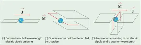
▲Figure 1.Principle of the design.
2 Magneto-Electric Dipole Antennas
To implement a complementary antenna,an appropriate electric dipole and magnetic dipole needs to be selected.Among many choices of electric dipoles,a planar dipole antenna is chosen(Fig.1a)and a wideband short-circuited patch antenna is chosen as the magnetic dipole(Fig.1b)[41].To combine these two antennas,a short-circuited patch is placed so that its open end can be connected to the horizontal planar electric dipole,as shown in Fig.1c[41].Based on this method,a new wideband antenna is developed after a detailed parametric study,and its prototype is shown in Fig.2[41].This antenna operates at 2.5 GHz.The planar dipole has a width W=60 mm(0.5λ)and a length L=30 mm(0.25λ).The shorted patch antenna has a length H=30 mm(also close to 0.25λ).The distance between the two vertical plates is S=17 mm,which is about 0.14λ.The width of the dipole and the patch Wis about 0.5λ.The size of the ground plane can be changed to adjust the back radiation—an acceptable choice is 160 mm×160 mm(1.3λ×1.3λ).
AnΓ-shaped probe is used as the feed.This consists of three parts made by folding a rectangular strip of metal.The first part is vertically oriented.One end is bonded to the coaxial launcher mounted underneath the ground plane.Together with the vertical plate of the shorted patch antenna,this part functions as an air microstrip line with a 50Ωcharacteristic impedance.The line transmits the signal to the second part of the feed.The second part is placed horizontally to excite the planar dipole and the shorted patch antenna simultaneously.The input resistance of the antenna depends on the length of this part.It also carries an inductive reactance that can affect the matching performance of the antenna.Together with the second vertical plate,the third part of the feed forms an open-circuited microstrip line.By choosing a suitable length for this part,its equivalent capacitive reactance can be used to suppress the inductive reactance that is caused by the second part.
The radiation patterns of a thin dipole,a planar dipole,and a magneto-electric dipole(shown in Fig.3)are simulated[41].They have the same ground plane size of 160 mm×160 mm and the same antenna height H=30 mm(0.25λ).For these three cases,the length of the dipole is L=60 mm(0.5λ),referring to an operating frequency of 2.5 GHz.For the first two cases,each antenna needs a balun for excitation.For the third case,the antenna is simply excited by aΓ-shaped strip feed.
The thin dipole in Fig.3a and the planar dipole in Fig.3b have the same radiation pattern,that is,high backradiation and unequal E-plane and H-plane patterns.For the magneto-electric dipole in Fig.3c,the beamwidths in the E-plane and H-plane become almost identical.More importantly,the level of back radiation is significantly lower than that of the first and second cases by about 10 d B.The antenna can also maintain low cross-polarization.

Figure 2.▶Amagneto-electric dipole.

▲Figure 3.Radiation patterns of(a)conventional dipole;(b)planar dipole;and(c)magneto-electric dipole.
Aprototype was built and tested.In Fig.4,the measured and simulated SWRcurves show that the antenna has an impedance bandwidth of 52%(SWR≤2)when operating between 1.75 GHz and 3.0 GHz[41].From the measured and simulated gain curves in Fig.5,it can be seen that antenna gain varies between 7.5 d Biand 8.2 d Bi across the operating frequency range,with an average value of 8 d Bi[41].Measured radiation patterns at frequencies of 1.75 GHz,2.5 GHz,and 3 GHz are shown in Fig.6[41].The broadside radiation patterns in both E and H planes are stable and symmetric over the operating frequency range.At the center frequency of 2.5 GHz,the H-plane beamwidth is 79°,slightly larger than the E-plane beamwidth of about 75°.More importantly,there is low cross-polarization and low back radiation over the operating frequency range.

▲Figure 4.Measured and simulated SWRagainst frequency for a wideband unidirectional antenna.

▲Figure 5.Measured and simulated gain againstfrequency for a wideband unidirectionalantenna.
3 Dual-Polarized Magneto-Electric Dipole Antenna
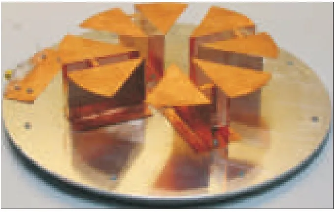
Based on the linear polarized design,a dual-polarized magneto-electric dipole antenna was fabricated(Fig.7)[42].This antenna also consists of electric dipoles and shorted patch antennas.The upper part of the antenna consists of two cross electric dipole elements with four square patches of dimensions P×P=29.2×29.2 mm2.The electric dipoles are connected with the lower part of the antenna,which comprises four vertically oriented shorted patch antennas—with H=28 mm(~0.23λ0)and W=16.5 mm(~0.14λ0)—connected together.The distance between the two vertical walls of a shorted patch antenna is S=62 mm.EachΓ-shaped strip feed consists of a transmission line and a coupled strip.
The transmission line,which is a linear tapered shape for impedance transformation,is located close to the corner of a folded vertical wall.The dimensions of the L-shaped coupling strip can be altered to achieve good impedance matching.The end of the coupling strip is not physically connected to the second arm of the dipole.It passes through the triangular hole of second arm of the dipole without connecting to the metal surface.The coaxial launcher underneath the ground plane is connected to the end of the linearly tapered line.To reduce mutualcoupling between the two input ports,the two orthogonal coupling strips have different heights.
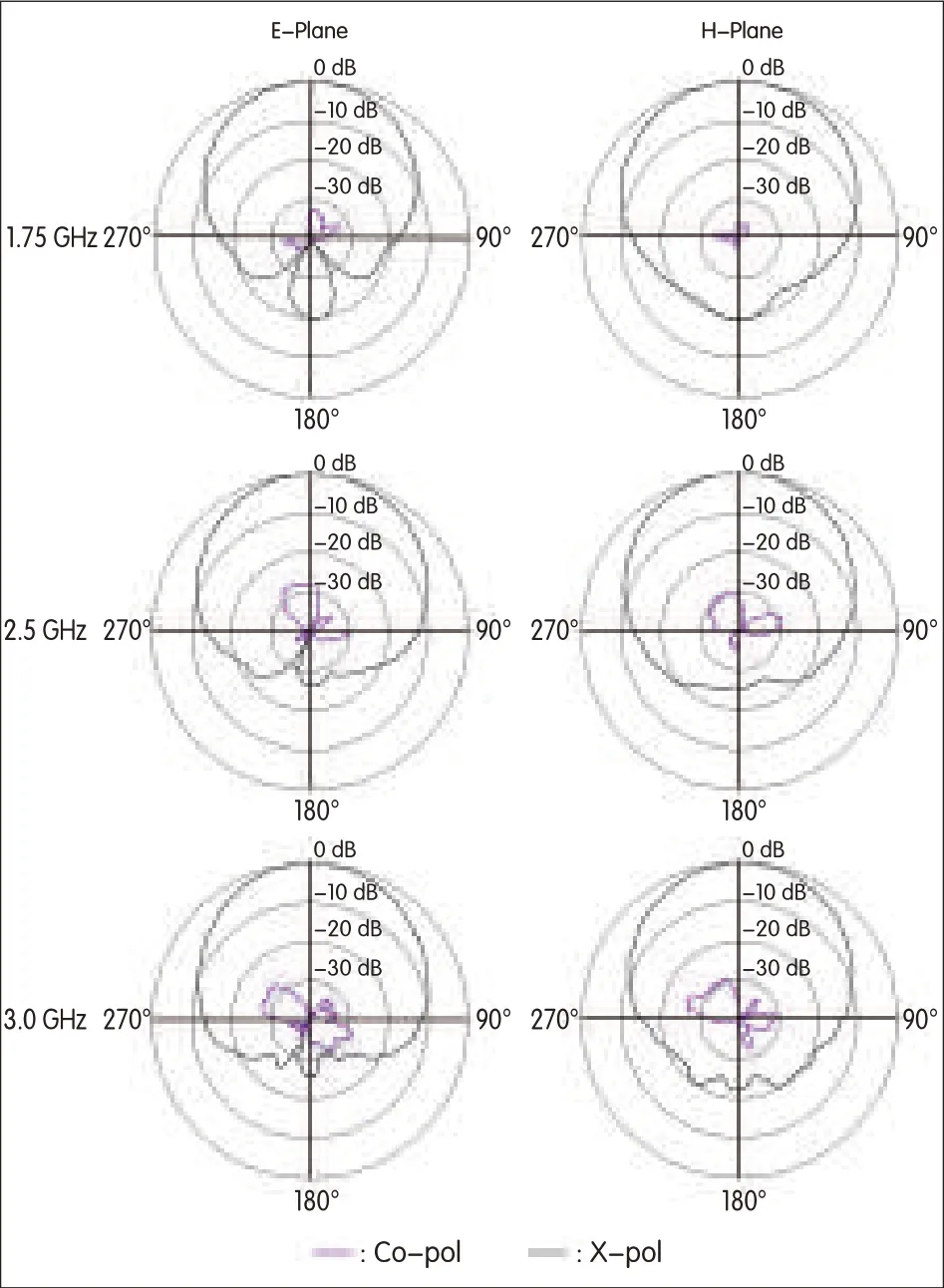
▲Figure 6.Measured radiation pattern at 1.75 GHz,2.5 GHz,and 3.0 GHz.

▲Figure 7.Geometry of dual-polarized magneto-electric dipole antenna(from[42]©2009 IEEEReprinted with permission).
The prototype was measured with an HP8753ESnetwork analyzer and a compact range measurement system.The results are shown in Fig.8 and Fig.9[42].The impedance bandwidths(SWR≤2)measured at ports 1 and 2 are 69.7%and 74.6%respectively.Because of the small difference in the dimensions of the coupling strips,the operating frequency ranges of the two polarizations are slightly different.As a result,the common bandwidth of the two ports is 65.9%,ranging from 1.7185 GHz to 3.409 GHz.Over the operating frequency range,the isolation between the two input ports is more than 36 d B.This fulfills the design requirement of mobile communications.
The variation in antenna gain is also shown in Fig.8.The gain is more than 9 d Biover a wide frequency range,with a maximum value of 9.5 d Bi.More precisely,the 3 d B gain bandwidth covers a range from 1.6 to 3.55 GHz.The antenna’s radiation patterns were obtained at frequencies of 2.109 GHz,2.707 GHz,and 3.306 GHz(Fig.10)[42].The radiation pattern is stable over the operating frequency range,and the back radiation is insignificant.The beamwidth varies only within a few degrees over the operating frequency range.If the size of the ground plane is reduced,the broadside radiation pattern does not change substantially,but back radiation and gain are affected.The antenna’s performance is not very sensitive to changes in the dimensions of the gap and height of the antenna.This confirms the robustness of the design.Measurement results agree very well with simulation.
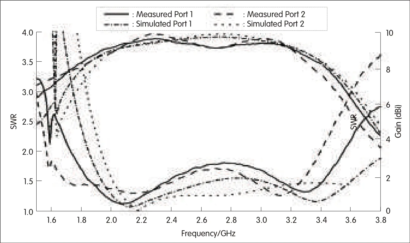
▲Figure 8.Return loss and gain variation of a dual polarized magneto-electric dipole antenna(in[42]©2009 IEEEReprinted with permission).

◀Figure 9.Isolation variation of a dual polarized magneto-electric dipole antenna(in[42]©2009 IEEEReprinted with permission).

▲Figure 10.Radiation pattern of a dualpolarized magneto-electric dipole antenna(in[42]©2009 IEEEReprinted with permission).
4 Horizontally Polarized Wideband Antenna with Conical Radiation Pattern
To create a horizontally polarized wideband antenna with conical radiation pattern,four magneto-electric dipoles are arranged in a ring,as shown in Fig.11 and Fig.12[43].The prototype is operated at 2 GHz.The dimensions shown in Table 1 were selected for excellent performance.The four magneto-electric dipoles are excited in-phase by a tapered power divider mounted underneath the ground plane.The upper part of the antenna is an electric dipole comprising a pair of sector-shaped horizontalplates.It is connected to the lower part of the antenna,which functions as a folded magnetic current.The magnetic current is provided by a vertically-oriented shorted patch antenna of height H=28 mm and that has aΓ-shaped strip feed.The separation between the two vertical plates is G=10.7286 mm.Each Γ-shaped strip has a transmission line section and a coupled strip section.The transmission line has a characteristic impedance of 50Ω.The thickness of the transmission line is 0.3 mm,and the separation between the transmission line and nearby vertical plate is 1 mm.The SWRand antenna gain are shown in Fig.13[43].The measured impedance bandwidth(SWR≤2)is about 38%,ranging from 1.61 GHz to 2.38 GHz.This is much larger than the bandwidth of many other designs of horizontally polarized conicalbeam antennas.The measured operating frequency band is slightly lower than the simulated operating frequency band by about 0.2 GHz,which is acceptable in practice.The measured gain is about 5 d Bion average,and the 3 d B gain bandwidth covers(and is larger than)the impedance bandwidth.The radiation patterns of the antenna at 1.6 GHz,1.8 GHz,and 2 GHz are plotted in Fig.14[43].These are stable over the operating band.Compared with the simulation results,the measured radiation patterns have slightly higher cross-polarization and back lobe levels.
5 Conclusions
This paper begins by discussing the design of a magneto-electric dipole antenna.This structure has several advantages,including stable radiation pattern with low cross-polarization,lowradiation,nearly identical E-and H-plane patterns,and stable antenna gain over the entire operating frequency range.The proposed antenna has more than 52%impedance bandwidth(for SWR≤2)with a stable gain of 8d Biand low back radiation.Adual-polarized antenna element based on the magneto-electric dipole is also presented.This antenna has about 67%(for SWR≤2)impedance bandwidth,and its isolation is more than 36 d Bover the impedance bandwidth.The maximum gain is 9.5 d Bi.Furthermore,a horizontally polarized conical beam wideband antenna is discussed.This antenna is low in profile(H=0.1867λ0)and has about 38%impedance bandwidth(for SWR≤2)and an average antenna gain of 5 d Bi.

▼Table 1.Dimensions of a horizontally polarized wideband antenna
▲Figure 11.Prototype of a horizontallypolarized wideband antenna(in[43]©2009 IEEEReprinted with permission).
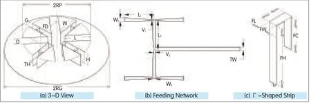
▲Figure 12.Geometry of a horizontally polarized wideband antenna(in[43]©2009 IEEE Reprinted with permission).
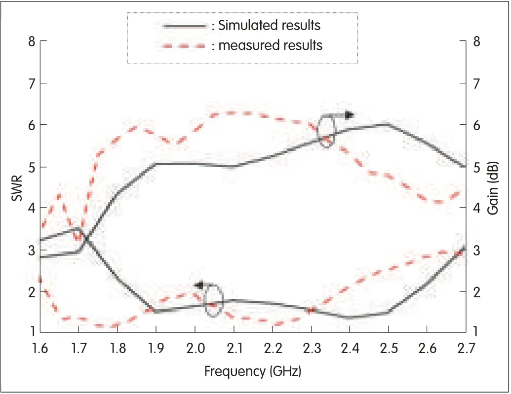
◀Figure 13.SWRand antenna gain of a horizontally polarized conicalbeam wideband antenna(in Figure 14.Measured radiation pattern of a horizontally polarized conicalbeam wideband antenna(in[43]©2009 IEEEReprinted with permission).

▲Figure 14.Measured radiation pattern of a horizontally polarized conical beam wideband antenna(in[43]ⓒ2009 IEEEReprinted with permission).

- ZTE Communications的其它文章
- RF Technologies and Challenges for Future MBRSystems in Cellular Base Stations
- ZTE Expects Sales Revenues from Enterprise Cloud Computing Products to Exceed$2 billion in 2011
- Broadband Power Amplifiers for Unified Base Stations
- Single Mode DRFilters for Wireless Base Stations
- Advanced Synthesis Techniques for Microwave Filters
- Privacy-Preserving Protocol for Data Stored in the Cloud