Sponge Effect on Coal Mine Methane Separation Based on Clathrate Hydrate Method*
ZHANG Baoyong (张保勇)**, CHENG Yuanping (程远平) and WU Qiang (吴强) National Engineering Research Center for Coal Gas Control, China University of Mining & Technology, Xuzhou 008, China Department of Safety Engineering, Heilongjiang Institute of Science & Technology, Harbin 5007, China
1 INTRODUCTION
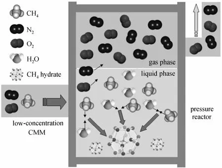
Clathrate hydrate, a crystalline solid composed of gas and hydrogen-bonded water molecules, is formed at the relatively high pressure and low temperature.When gas hydrate crystals are formed from a mixture of gases, the concentration of these gases in the hydrate crystals is different from that in the original gas mixture. This is the basis for the utilization of hydrate formation-dissociation as a separation process. Fig. 1 illustrates the basic idea behind the gas separation using gas hydrate technology. A CH4/N2/O2mixture is fed into the process where it comes into contact with water at suitable temperature and pressure conditions,and forms hydrate crystals. Due to a sharp difference in hydrate formation pressure between CH4, N2and O2,it is expected that CH4will preferentially go into the hydrate crystal phase. The crystals are separated and subsequently dissociated to create the CH4-rich stream while the rest constitutes the CH4-lean one, as shown in Fig. 1 [1].

Figure 1 Hydrate based separation process
Wu and Zhang [2] proposed the new method to separate low-concentration coal mine methane (CMM)based on hydrate in 2006. The initial and critical step for the development of hydrate-based separation technology involves mild operation conditions, high-speed separation and high recovery efficiency [3, 4]. Therefore,proper methods to promote the hydrate formation are the hot issues for CMM separation based on hydrate.There have been a number of methods proposed to enhance the hydrate formation, including chemical [5,6] (adding a certain quantity of thermodynamic promoters) and mechanical methods [7-12] (stirring,spraying of liquid using a nozzle and bubbling of gas using a single pipe or an orifice plate).
However, it was found that few literatures concentrate on the sponge effect on CMM separation based on hydrate. Thus, twelve tests (three CMM samples,three sponge volumes and no sponge present) were performed to study the sponge effect on the hydrate formation rate, gas volume stored in hydrate and CH4mole fraction in hydrate phase during CMM separation process. The primary objective of this work was to determine if the polyurethane sponge could promote hydrate formation, particularly if it can increase gas volume stored in hydrate and the separation effect.
2 EXPERIMENTAL
2.1 Apparatus and materials
The experimental apparatus used in this work was shown in Ref. [4]. It mainly consists of a highpressure hydrate crystallizer (CR) constructed of 316 stainless steel, a thermotank, a cold light illuminator, a CCD imaging system, a pressure sensor, a data-logger and a personal computer.
The crystallizer has two circular viewing windows on the front and back (Inner diameter 3.0 cm and total available volume about 150 ml). The reactor can attain a maximum pressure of 10 MPa. The operation temperature ranges from -10 °C to 50 °C. The plan dimensions of the sponge are 20 cm×3 cm. The volumes of three sponges are 40 cm3, 60 cm3and 80 cm3, respectively. The schematic diagram of test section is shown in Fig. 2.

Figure 2 Schematic diagram of test section

Table 1 The purity and source of reagents

Table 2 Experimental results of THF-SDS-sponge-gas reaction system
Table 1 lists the reagents used in this study. The components of three synthesized gas samples are as follows: Sample A (mole ratio: 24.90% CH4, 60.20%N2and 14.90% O2), Sample B (mole ratio: 40.40%CH4, 49.50% N2and 10.10% O2) and Sample C (mole ratio: 59.50% CH4, 35.20% N2and 5.30% O2). Distilled water is weighed using a balance with a precision of 0.1 mg. The binary solution with volume of 60 ml is composed of 0.50 mol·L-1tetrahydrofuran (THF)and 0.20 mol·L-1sodium dodecyl sulfate (SDS). The volume of the polyurethane sponge is analyzed using the biological microscope Leica DM1000-4N30 and image analysis software Coxpix Simple PCI. The sponge has the mass density 0.36 g·cm-3, mean porous diameter 0.25 mm, porous ratio 90% and open porosity 74%.
2.2 Results
The separation tests of three gas samples were firstly performed in the binary solution at 4.00 MPa without sponge addition. The macroscopic phenomena of gas hydrates were observed. Then chromatography analysis was performed to measure the gas components during the hydrate formation. When the hydrate formation finished, CH4mole fraction in hydrate phase was measured.
After these three tests were finished, the separation tests with 40, 60 and 80 cm3sponges were added into the solution to study the sponge effect on the gas hydration during separation. The experimental parameters and results are listed in Table 2.
3 DISCUSSION
3.1 Hydrate formation rate
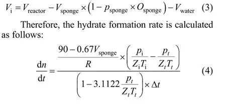
Hydrate formation rate plays an important role in making hydrates for the coal mine gas separation. The formation rate of gas hydrate is governed by a multitude of factors including pressure, temperature and gas composition, which are also called PVT-effects. Also,the rate of hydrate formation is determined by the combined effects of heat, mass and momentum transport. The overall rate of hydrate formation depends on PVT-effects, transport-effects and reaction-effects. It can be obtained by differentiating the gas volume Δntdefined as the difference between the gas volume at initial time andttime. It can be calculated using gas equation of state as shown in Eq. (1).

wherepi,pt,Vi,Vt,Zi,Zt,TiandTtare the pressure,volume, compressibility factor and temperature of gas in the reactor at initial time andttime, respectively. The compressibility factors for different gases can be obtained by Benedict-Webb-Rubin-Starling state equation.
The mixed gas composed of CH4, N2and O2can form structure II hydrate in THF present solution. Its theoretical water/gas mole ratio is 136/24,i.e., the hydration number is 5.67. The volume of one mole of water increases by 0.25 when it forms crystal cells.Therefore, the following equation is obtained.

When the sponge volumeVsponge, porous ratiopsponge, open porosityOspongeand the liquid volume in the reactor are included, the following equation can be obtained:

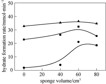
Figure 3 shows the hydrate formation ratevs. the sponge volume for three gas samples. It is clear from Fig. 3 that (1) sponge increases the hydrate formation rate as compared with the solution without sponge;(2) the hydrate formation rate varies among CMM with different mole fraction of CH4. CMM with high CH4mole fraction has high gas hydrate formation rate,indicating it is liable to form hydrates. The hydrate formation rate of gas sample C attains to the maxima 8.25×10⁻²m3·min-1in the solution with 80 cm3sponge.This also verifies the necessity to enhance the low concentration CMM separation; and (3) the larger sponge volume, the higher gas hydrate formation rate,demonstrating the sponge effect on the kinetics of gas hydrate formation.

Figure 3 Variations of hydrate formation rate with sponge volume● gas A; ■ gas B; ▲ gas C
3.2 Gas volume stored in hydrate phase
After the gas hydrate formation, the thermotank is set at -5 °C and the residual gas pressure is vacuumized to -0.1 MPa. Then the temperature is increased to 25 °C to enhance the hydrate dissociation.Finally, the gas pressure after separation is measured.Based on the measured gas pressure, the gas volume in hydrate phase can be calculated.

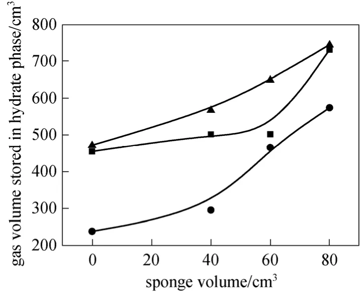
Figure 4 Variations of gas volume stored in hydrate phase with sponge volume● gas A; ■ gas B; ▲ gas C
Figure 4 shows the relationship between the gas volumes in hydrate phase and the sponge volumes for different gas samples. It can be seen from Fig. 4 that(1) the higher CH4concentration in CMM, the larger the gas volume in hydrate phase; and (2) the higher sponge volume, the larger the gas volume in hydrate phase, indicating the sponge enhanced the mass transfer between the gas and solution, and more gas involves in the hydrate formation. For example, the increased gas volumes in hydrate phase for gas samples A, B and C are 336.4 cm3, 277.14 cm3and 273.78 cm3,respectively, comparing the solution with no sponge and 80 cm3sponge present.
3.3 CH4 mole fraction in hydrate phase
After the gas hydrate dissociation, the CH4mole fraction in hydrate phase is measured by Gas Chromatography. The CH4mole fraction in hydrate phase is used to evaluate the separation efficiency of gas mixtures containing CH4, N2, and O2. Table 2 clearly shows that following a one stage hydrate formation/decomposition process for CMM gas mixtures separation, the CH4mole fractions for gas samples A,B and C rise from 24.9%, 40.4%, 59.8% to approximately 40.01%, 58.46% and 77.86%, respectively.

Figure 5 Variations of CH4 concentrations in hydrate phase with sponge volume● gas A; ■ gas B; ▲ gas C
Figure 5 shows the CH4mole fraction in hydrate phase vs. the sponge volume for different gas samples.The curves are relatively smoothing, indicating that the sponge has little effect on the CH4mole fraction in hydrate phase. It may be due to the reason that sponge does not participate in the hydrate formation, though it affects the mass transfer in the gas hydration process.
3.4 Influence mechanism of sponge
The addition of porous media sponge changed the previous reaction system. The gas hydration during CMM separation for sponge-THF-SDS-CMM-water solution system follows the reaction-diffusion mechanism. The large porous ratio and internal surface area of sponge provides more channels for gas-liquid mass transfer. The abundant CMM molecules and water molecules are absorbed in the sponge. These molecules are subjected to the pressure and intermolecular force. Therefore, sponge provides the material base for the hydrate formation between the host and guest molecules (CMM and water molecules), and promotes the mass transfer. Meanwhile, the specific porous characteristics of the sponge supply more reaction platforms for the gas hydration to enhance the heterogeneous nucleation [13]. With the proceeding of the hydrate formation, the driving force and more channels further reinforce the mass transfer between the CMM and water molecules, increasing the hydrate formation rate. Regarding the three gas samples and three sponge volumes in this study, the best sponge to promote CH4capture with 60 cm3was found in the range examined.
4 CONCLUSIONS
In this study, sponge effect on the gas hydrate formation during CMM separation process is investigated in THF-SDS binary solution with absent and present of sponge. The sponge effect is quantitatively analyzed in terms of hydrate formation rate, gas volume stored in hydrate and CH4mole fraction in hydrate phase. The sponge promotes the mass transfer of gas in the hydration during CMM separation. The results show that (1) regarding the three gas samples examined, sponge with volumes of 40, 60 and 80 cm3significantly enhances the hydrate formation; (2) with the increase in the sponge volume, the gas volumes in hydrate phase increase, indicating the sponge promotes the mass transfer between CMM molecules and water molecules; and (3) The sponge has little effect on the CH4mole fraction in hydrate phase. It is due to the reason that the sponge does not take part in the hydration reaction, and thus, it has no effect on the CH4mole fraction in hydrate phase and the thermodynamics of CMM hydrate formation. These results reveal that sponge can be added in the hydrate-based separation method to enhance the kinetic process of gas hydrate formation during separation.
1 Zhang, B.Y., Wu, Q., “Thermodynamic promotion of tetrahydrofuran on methane separation from low-concentration coal mine methane based on hydrate”, Energy Fuels, 24 (4), 2530-2535 (2010).
2 Wu, Q., Zhang, B.Y., “Thermodynamic effect of surfactant on gas hydrate formation”, CIESC Journl, 57 (12), 2793-2797 (2006).
3 Zhang, B.Y., Wu, Q., “Effect of THF on the thermodynamics of low-concentration gas hydrate formation”, Journal of China University of Mining & Technology, 38 (2), 203-208 (2009).
4 Wu, Q., Zhang, B.Y., “Effects of sodium dodecyl sulfate and kaolin on low-concentration mine gas hydration separation”, CIESC Journl,60 (5), 1193-1198 (2009).
5 Zhong, Y., Rogers, R.E., “Surfactant effects on gas hydrate formation”, Chem. Eng. Sci., 55, 4175-4187 (2000).
6 Sloan, E.D., Koh, C.A., Clathrate Hydrate of Natural Gases 3rd ed.,Taylor & Francis Group LLC, New York, 116-121 (2008).
7 Servio, P., Englezos, P., “Morphology of methane and carbon dioxide hydrate formed from water droplets”, Environmental and Energy Engineering, 49 (1), 269-276 (2003).
8 Tsuji, H., Kobayashi, T., Ohmura, R., “Hydrate formation by water spraying in a methane + ethane + propane gas mixture: An attempt at promoting hydrate formation utilization large-molecule guest substances for structure-H hydrate”, Energy & Fuels, 19, 869-876(2005).
9 Mork, M., Gudmundsson, J.S., “Hydrate formation rate in a continuous stirred tank reactor: experimental results and bubble-to-crystal model”,In: Proceedings of the Fourth International Conference on Gas Hydrates, Yokohama (2002).
10 Topham, D.R., “The formation of gas hydrates on bubbles of hydrocarbon gases rising in seawater”, Chem. Eng. Sci., 39 (5), 821-828(1984).
11 Chen, L.T., Sun, C.Y., Chen, G.J., “Measurements of hydrate equilibrium conditions for CH4, CO2, and CH4+ C2H6+ C3H8in various systems by step-heating method”, Chin. J. Chem. Eng., 17 (4),635-641 (2009).
12 Ma, Q.L., Chen, G.J., Guo, T.M.. “Prediction of structure-H gas hydrate formation conditions for reservoir fluids”, Chin. J. Chem. Eng.,13 (4), 484-490 (2005).
13 Kashchiev, D., Firoozabadi, A., “Nucleation of gas hydrates”, Journal of crystal growth, 243, 476-489 (2002).
 Chinese Journal of Chemical Engineering2011年4期
- Chinese Journal of Chemical Engineering的其它文章
- Adsorptive Recovery of Uranium from Nuclear Fuel Industrial Wastewater by Titanium Loaded Collagen Fiber*
- Salting-out Extraction of 2,3-Butanediol from Jerusalem artichoke-based Fermentation Broth*
- Investigation of Mg2+/Li+ Separation by Nanofiltration*
- Vapor-Liquid Equilibrium of Ethylene + Mesitylene System and Process Simulation for Ethylene Recovery*
- Purification and Characterization of a Nonylphenol (NP)-degrading Enzyme from Bacillus cereus. Frankland*
- Modeling of Surface Tension and Viscosity for Non-electrolyte Systems by Means of the Equation of State for Square-wellChain Fluids with Variable Interaction Range*
