
Study of Load Modeling Technology on Hardware-in-the-Loop Simulator of Gun Servo System
2011-03-09 11:57:30WANGHongping王红平CAOGuohua曹国华DONGYanliang董彦良HEChi赫赤SHIDemin史德民
Defence Technology 2011年1期
关键词:国华
WANG Hong-ping(王红平),CAO Guo-hua(曹国华),DONG Yan-liang(董彦良),HE Chi(赫赤),SHI De-min(史德民)
(1.School of Electromechanical Engineering,Changchun University of Science and Technology,Changchun 130022,Jilin,China;2.School of Mechatronic Engineering,Harbin Institute of Technology,Harbin 150001,Heilongjiang,China;3.Baicheng Ordnance Test Center of China,Baicheng 137001,Heilongjiang,China)
Introduction
The gun servo system is an important component in the weapon systems,such as anti-aircraft gun and ship-based gun,etc.It receives the instruction from the fire control computer,drives gun to aim at targets quickly,accurately and stably,and fires at appropriate time to destroy the targets.Its performances directly affect the combat effectiveness of weapon systems[1].The firing performance of anti-aircraft gun and shipbased gun in motion is an important tactical and technical index.According to the National Military Standard,in the approval test,the comprehensive and systematic assessment for the performances of the gun servo system in motion is an important step to ensure that the weapon system meets the design requirements.
HWIL simulation technology has been widely used in the design,research and approval test for the weapon systems,For example,the simulation technology is adopted for the fire control system of a certain shipbased gun[2-4],an integrated and digital fire control simulation system for ship-based gun is developed by using software WISE[5].
The HWIL load simulator of the gun servo system is used to simulate a certain single load moment or compound moment of inertia,shooting impact,impacts of road spectrum or sea wave in the laboratory when the gun servo system operates in the harsh environment,provide test environment close to real conditions,complete some test items of the weapon system,such as performance,firing,environment adaptability and reliability tests,and evaluate the performances of the gun servo system in motion.The various models of the moments can directly affect the realities of the test items.The models of inertia load and shooting impact were established in some references[6],thus,this paper focuses on the road spectrum impact and sea wave impact models to solve the key problems in HWIL simulator for the gun approval test.
1 System Components of HWIL Simulator
In the simulator,a computer servo-controller and a four-quadrant vector AC variable frequency feedback loader are used as the control elements,a generator is adopted as the load simulation elements,the rotation and torque are transmitted by using mechanical drive device,torque sensor,angle measuring device and transmission ratio simulation device.According to the given waveform and test requirements,the simulator outputs the inertia moment,impact moment of road spectrum,impact moment of sea wave and shooting impact moment for the gun servo system.
The load simulator’s block diagram is shown in Fig.1.HWIL simulator consists of two parts,the first one is tested weapon system bordered by dotted lines,which includes the tested motor,control box,angle measuring sensor and tacho-generator of the servo system,and another part includes control computer,gearbox,torque sensor,data acquisition device,generator load simulating device,transmission ratio simulation device,etc.
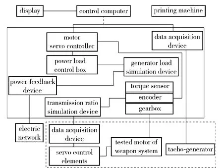
Fig.1 Block diagram of HWIL simulator
A wind cooling device is adopted to prevent the generator from overheat caused by frequent switching between high and low speeds.Meanwhile,a heat insulation container bordered by solid lines in Fig.1 is set,in order to ensure the normal operations of sensors,generator,gearbox and bearings,etc.in low temperature environment.The components except the tested part are inside the container.The container also has wind inlet and outlet for the wind cooling of generator in high temperature test.
A movable high rigidity workbench is used to fix the tested motor of gun servo system,load simulation structure and sensing element.Its 3D diagram is shown in Fig.2.
A control computer is used to manage the whole system.It is connected to the host computer with cable,and operated in room temperature.
2 Analyses of Load Moment Models
The HWIL simulator is mainly used to simulate various of road spectra when the self-propelled gun is moving,various of sea conditions for the ship-based gun,shooting impact and inertia moment of gun,so that their influences on the combat effectiveness can be analyzed in above conditions.The moment models are attached to driving motors of tested weapon system through the mechanical transmission devices of Load simulation system.So whether the simulations of various load moments are true and reliable,it lies in that various analog signals given are close to the actual situation.
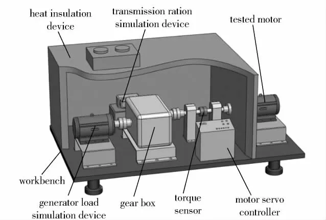
Fig.2 3D diagram of HWIL simulator
The inertia moment of weapon system is caused by its moment of inertia.Ignored the viscous friction coefficient,the inertia moment is the function of the moment of inertia and the rotary acceleration,that is,MG= - J,where MGis the inertial load moment,J the rotary inertia converted to the motor axis of servo system,the angular acceleration.The angular acceleration can be obtained from the angle information acquired by encoder.
The shooting impact moment depends upon the shooting situation.Generally,it is approximately regarded as a rectangular or triangular wave with a certain frequency.
Various of road spectra impact on the gun in motion and various of sea conditions for the ship-based gun are often solved on the basis of sine wave.In order to describe actual situation,the models solved must be acquired based on the actual situation.
This paper focuses on the establishment of the road spectrum and sea wave models,and the simulations are set up by MATLAB for these typical models,
2.1 Establishing of Road Spectrum Model
The types and grades of pavements are defined in the National Military Standard.However,the lack of the test specifications and test standards of special roads makes them not use for weapons development and qualification test.So it is important for load modeling test that the mathematical models of all kinds of road spectra can be established.
2.1.1 Definition of road roughness
The road roughness is one of the most important indexes of pavement performance,also a key factor causing the vehicle vibration.It not only affects the traffic safety of the vehicle,but also determines the mechanical reliability of the vehicular equipment.Usually,it is defined as the pavement’s height change h(x)along the road’s direction x[7],which is measured in the road’s vertical section by a special pavement gauge,as shown in Fig.3.
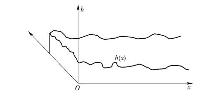
Fig.3 Vertical section of road
General,the characteristics of road roughness can be described by statistical models.The spatial frequency power spectrum density(PSD)of road is used as statisticalcharacteristics ofroad roughness[8]. A process of spectral density Gh(n)is the Fourier transform of its auto-correlation function Rh(τ).Namely:
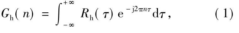
where n is length frequency or spatial frequency(c/m),expressed of the number of ups and downs on per meter length.
Reference to international standard classification method of road ISO/TC108/SC2N67,‘vehicle vibration input-road roughness method’GB7031—86 is drafted in Chinese.It provided the power spectrum of road roughness expressed by the following formula
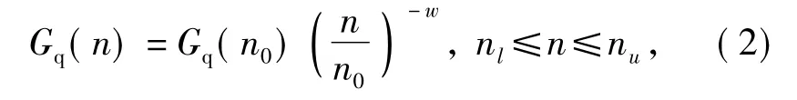
where n is the spatial frequency(m-1),that is the reciprocal of wavelength λ,generally,the bandwidth is 0.011 m-1<n<2.83 m-1;n0is spatial reference frequency,n0=0.1 m-1,Gq(n0),bearing road rating,is the power spectrum value(m3)of n0,known as the road roughness coefficient;w frequency index is the log-log slope,which determines the frequency spectrum structure of road,generally,w=2.
2.1.2 Simulation of pavement roughness
Known power spectral density of road Gq(n),varieties of simulations can be constructed using road roughness sequence.At present,the simulations of road roughness are harmonic superposition method,inverse Fourier transform method,AR model method.Inverse Fourier transform method could obtain a higher accuracy of simulation in the frequency band;AR model is a parametric spectrum estimation method,and can better approximate the target spectrum.Here the Fourier transform and AR model method are used in this article.
The basic idea of inverse Fourier transform gets series of discrete Fourier transform modulus through its corresponding road power spectrum,and then obtains the phase spectrum as the phase angle input using the random sequence of a normal distribution to Fourier transform.So amplitude spectrum is constructed,then its inverse Fourier transform is road roughness random sequence[9].
The basic idea of AR model is that the random road roughness h(x)is generated by a model based on white noise.It equals a digital filter,namely the white noise becomes similar spectral density or discrete random process of related functions.
When a random road roughness is described by its power spectral density based on GB7031—86,autocorrelation function R(x)of road roughness h(x)can be obtained through inverse Fourier transform

AR model is defined as follows
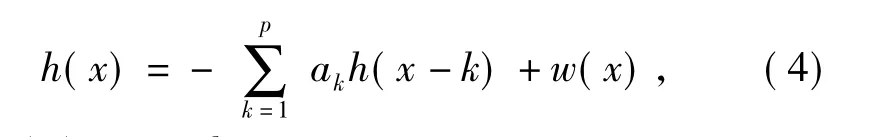
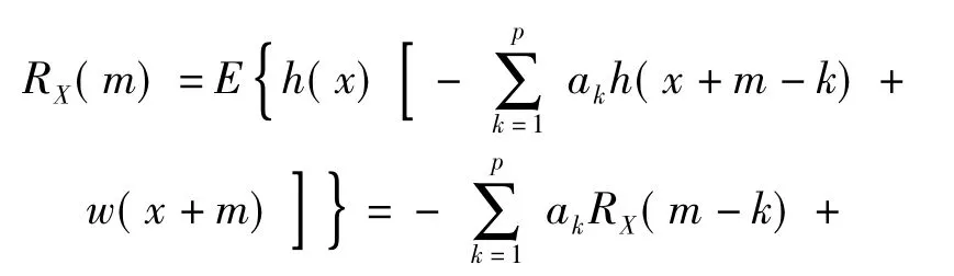
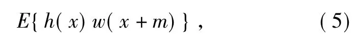
where w(x)is a white noise sequence,its variance is σ2w.Put equation(4)into the auto-correlation function
where
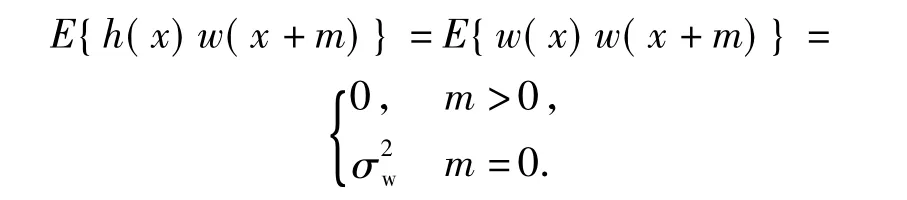
h(x)is only related to w(x),and has nothing with white noise sequence after x moment.The autocorrelation sequence can be reduced to
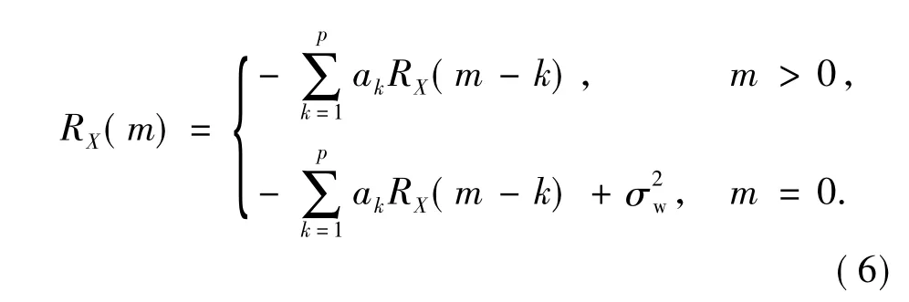
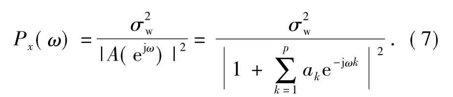
Equation solution can obtain the coefficients akandavailable,which will determine the sequence of road roughness.At the same time AR model spectrum estimation can be used.
2.1.3 Establishing of additional noise model of test road power spectrum
Common test roads in GJB are wavy road,washboard road,gravel road and so on.Wavy road and washboard often used in the test road are based on sine wave.Taking an existing sine test road as a sample,based on relevant information of test road,the paper constructs the digital model of strengthen test road and then analyzes the construction of roads and the level of classification test.
According to the actual engineering situation,sine test road structured in test place is not in strict conformity with drawings,its cycle is approximate,and the noise exists on the road surface.Thus,the actual road condition can be simulated by adding an additional noise to the sine waveform.Currently,the grade A pavement is the best one in the road construction.Thus,it is feasible that the grade A pavement’s roughness simulated by inverse Fourier transform is used as the noise input.The noise can added to the sine pavement roughness to simulate the actual pavement,and then,the power spectrum can be calculated to classify the pavement with approximate cycle.
Now,take the FA-compound road roughness,that is,the grade F road roughness random sequence added the grade A road roughness random sequence,as an example to show the above method’s feasibility.According to reference[8],the roughness sequence of the grade F pavement can be obtained by the Fourier inverse transform,the roughness sequence of grade A pavement can be also gotten by using the same method,then,added the grade A road roughness to the grade F road roughness,the new random sequence of FA road roughness is obtained,as shown in Fig.4.
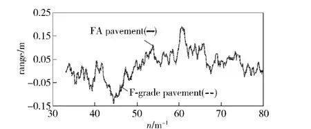
Fig.4 Comparison with grade F road’s power spectrum
The new grade FA wave sequence should be checked by a turn check method[8]first,and the check result of sequence FA is stationary.Then,AR model method can be used to estimate the power spectrum.Compared with the pavement grades in the National Military Standard,it can be seen that the change of the power spectrum of the new grade FA sequence is close to the grade F sequence,and almost coincides with it.This shows that the new road roughness added A grade road roughness has little effect,and does not influence the power spectrum of original road roughness.This method can identify the grades of sine test roads of various cycle and amplitude,and then load simulation system can achieve the different test road simulations according to the requirements.
2.2 Sea Wave Model
When the naval ship navigates by sea,because of the disturbance of wave,it will take place six kinds of movements,such as roll,pitch,yaw,sway,surging,heaving,the most possible movement is roll and its range is the biggest.The sea wave model simulates the additional moment of servo system generated by ship’s rolling,and the models for both orientation and pitch are required.
2.2.1 Rolling model in orientation system
The ship’s rolling is denoted as θ(t),and the friction moment MJFzcaused by the component normal to the deck of the gyration part’s gravity,when the ship is rolling,can be written as

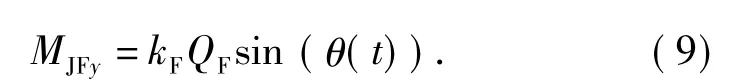
The friction moment MJFycaused by the reaction force of the component parallel to the deck of the gyration part’s gravity,when the ship is rolling,can be written as
The friction moment MSF1caused by the reaction force of the tangential inertia force from pedestal ring,when the ship is rolling,can be written as
In the state of the ship rolling and not shooting,the total moment of orientation system is
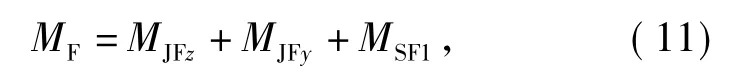
In equations(9)~(10),QFis the weight of gyration part,kFthe friction factor of gyration part,R'the distance between the warship’s gravity center and the gyration part’s gravity center.
2.2.2 Rolling model in pitch system
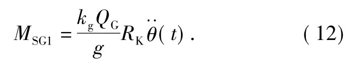
The friction moment MSG1caused by the reaction force of the tangential inertia force from trunnion,when the ship is rolling,can be written as
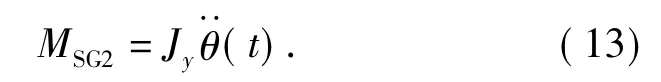
The pitch part’s inertia moment MSG2caused by the rolling acceleration,when the ship rolling,is
In the state of the ship rolling and not shooting,the total moment of pitch system is

In equations(12)and(13),QGis the weight of pitch part,kgthe friction factor of pitch part,RKthe distance between the warship’s center-of-gravity and the pitch part’s center-of-gravity.
For a certain gun,QF,QG,kF,kg,R'and RKare constants.From equations(9)~(11),(12)~(14),the total moments of orientation and pitch system can be found out.When the rolling is simulated,the computer outputs the calculation results,and then,the sea wave load moment is obtained by simulator.
2.2.3 Law of the actual ship’s rolling
Generally,the ship’s rolling θ(t)can be simplified as a sine function for convenience. However,when the ship navigates by sea,its speed and direction impact the waves greatly,which is equivalent to change the wave’s frequency.Therefore,the impact of waves in ship’s motion should be considered for law θ(t)of the actual ship’s rolling.The encountered frequency[11]of the ship to the sea wave can be expressed as
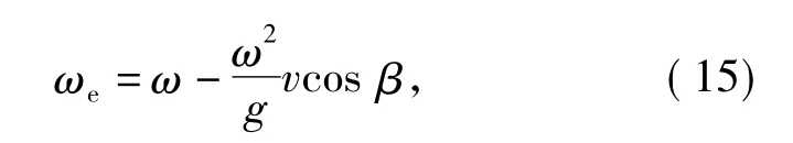
where ω is the wave frequency,g the gravity acceleration,v the ship speed,β the encountered angle.The wave height with encountered frequency is
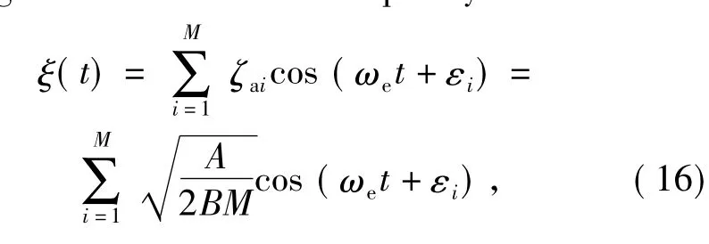
Based on the ship swing theory[10],when the ship rolls in the sea,the effective wave angle of the sea wave to the ship is
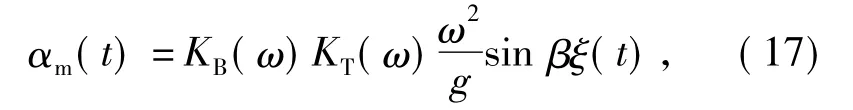
where KB(ω)and KT(ω)are correction factors condidering the ship’s width and limited draft.
The mathematical model of ship rolling is often based on Conolly equation[10-11],that is,
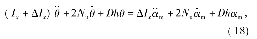
where Ixis the rolling rotary inertia,ΔIxthe additional rotary,2Nuthe rolling damping coefficient,D the ship’s displacement,h the ship’s metacentric height,θ the rolling angle,αmthe effective wave angle.
The output equation is
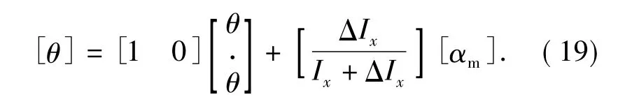
According to the inherent cycle of ship Tθ,the sum of additional rotary inertia and moment of inertia Ix+ΔIxcan be obtained.
The roll damping coefficient 2Nuis
So,the rolling angle considered actual wave situation is brought into the additional torque equation both orientation and pitch on gun servo system,and then sea wave impact model can be close to the actual situation.
3 Model Simulation
3.1 Model Simulation of Additional Noise Method for Test Road
A certain sine wave sample is selected to construct digital model of test road,and then the frequency composition and road grade is analyzed.
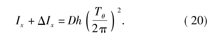
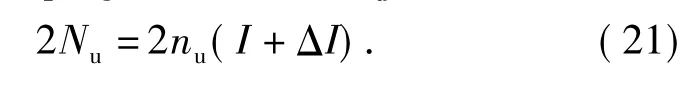
The sine road is 250 m in length and 4 m in width,the vertical gradient is less than 5‰,shown in Fig.5.The waveform function is

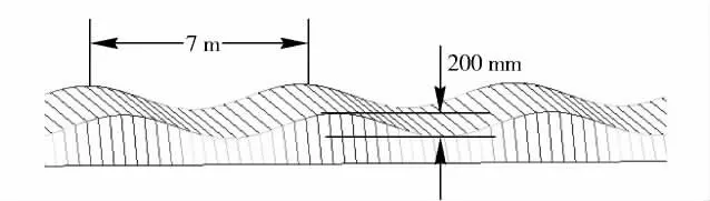
Fig.5 Sketch of sine road
Assumed that the sine road is constructed according to ideal conditions,the roughness of sine road is a periodic function,and theoretical power spectrum is Equation(23).But it can not obtain road grade according to the power spectral density in National Standard GB7031—86.
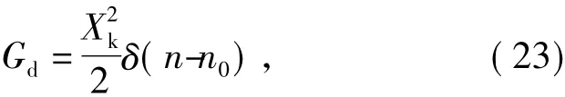
where n0=0.142 85 m-1,which represents the spatial frequency of sine pavement.
According to additional noise method,the sinusoidal wave road added grade A road roughness sequence can be regarded as the actual sinusoidal wave road in the analysis.Its cycle is approximate,and it can obtain road grade through power spectral density area.The new sinusoidal waveform added grade A road roughness is shown in Fig.6.As its spatial frequencies is in 0.011 ~ 2.83 m-1,new sine wave as test road can get power spectrum estimation through AR model method.Its power spectrum area is SPSD=5 011.2 m2,the road grade is E+ .The result is shown in Fig.7.
It is obvious that additional noise method of power spectrum of test road can construct various digital model of test road,and obtain test road grade.Based on additional noise method,the types and grades of test road in standard military will be specified,and then the actual spectrum model of test road close to the actual condition will be gotten.It can provide realistic simulating model of test road for load simulating of gun servo system.
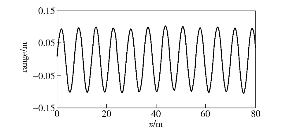
Fig.6 New sinusoidal road added grade A road sequence
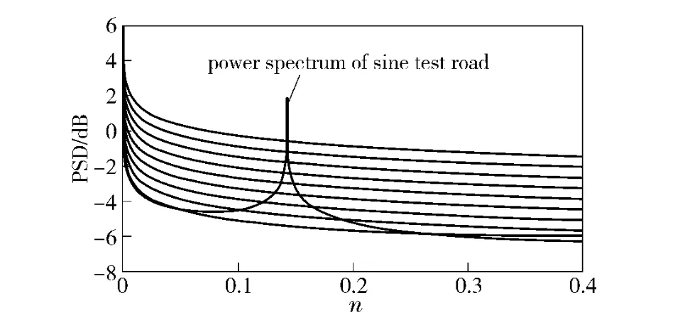
Fig.7 Comparison of power spectrum for sine test road
3.2 Model Simulation of Sea Wave Impact Moment
Take 5 level sea wave of h1/3=3.1 m and speed v=18 knot as an example.Assumed that the ship’s displacement D=2 000 t,the inherent rolling cycle Tθ=9 s,the ship’s metacentric height h=1.15 m,the non-dimensional damping 2nu=0.29,the ratio of additional roll moment of inertia to the total moment of inertia is 0.2.The simulation program of the wave impact moment on the weapon system is developed by MATLAB,and the additional moments of orientation and pitch systems can be simulated when encountered angles are 45°,90°and 135°,respectively.Fig.8 and 9 show the additional moments of orientation and pitch systems at different encountered angles.
It can be seen from these figures that the ship navigates along sea waves,the encountered frequency is lower,and the additional moments of orientation and pitch systems change slow and small,when the en-countered angle is 45°;the ship navigates against the sea waves,the encountered frequency is higher,and the additional moments of orientation system and pitch system change acutely and greatly,when the encountered angle is 135°;the effects of rolling on the weapon system are moderate,when the encountered angle is 90°.
It is obvious that the wave impact moment model established in this paper can simulate the wave impact moments in different sea conditions,different speeds and directions.The model can more accurately reflect the actual operation environment of the ship,and be very practical.
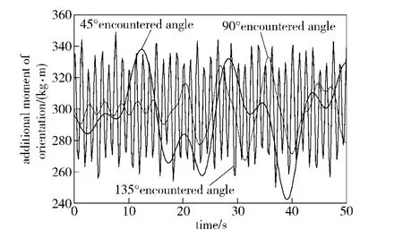
Fig.8 Additional moment in orientation system
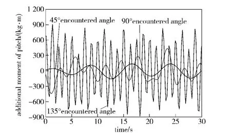
Fig.9 Additional moment in pitch system
4 Conclusions
Whether HWIL simulator of gun servo system is able to provide varieties of load moment close to the actual conditions,the primary problem is that load moment models given must be load of real situation.In the paper various of road spectrums impact models on the gun in motion and various of sea wave impact models for the ship-based gun are analyzed in detail,and they are constructed closer to the military standard conditions through the theories of waves and road spectrum,combined with the ideal sine wave and the actual condition.Simulation results show that the model built is correct,and the load moment models built are more scientific and reasonable.
[1]HE Chi,CAO Jian,ZHAO Ke-ding,et al.Measure-control system for performance of gun servo system based on IRMX operating system[J].Journal of Gun Launch &Control,2005,(1):65 -68.(in Chinese)
[2]CONG Shu-xue,WANG Mao-lin,ZHENG Jin.Application of simulation technology in new naval gun weapon system test[J].Intelligence Command Control and Simulation Technology,2002,(7):63-67.(in Chinese)
[3]CHENG Jian-qing.Simulation technology of the new naval gun integrated fire control system[J].Journal of System Simulation,2003,15(3):421-425.(in Chinese)
[4]LI Gang,XU Li-qun,CHEN Ke.Study and realization of load simulation of servo system of naval gun[J].Gun Launch& Control Journal,2004(3):57-60.(in Chinese)
[5]CHENG Jian-qing,GU Hao,LI Su-min.Integrated simulation environment for weapon system and simulation system[J].Journal of System Simulation,2001,13(3):337-341.(in Chinese)
[6]LOU Yue.Research and design of load system based on servo system[D].Nanjing:Nanjing University of Technology and Engineering,2007:6 -14.(in Chinese)
[7]ZHAO Ji-hai,WANG Zhe-ren,GUAN Chao-li.Measurement,analysis and application of road roughness[M].Beijing:Beijing Institute of Technology Press,2000:9 -90.(in Chinese)
[8]ZHANG Ya-ou,MA Ji-sheng,WU Da-lin,et al.Modeling and simulation of road roughness based on the method of reverse fourier[J].Journal of Hebei University of Technology,2005,34(6):66 -69.(in Chinese)
[9]WANG Xin-ming,WANG Bing-gang.Expressway pavement power spectral density[J].Journal of Traffic and Transportation Engineering,2003,3(2):53 -56.(in Chinese)
[10]LIU Ying-zhong,LIAO Guo-ping.Movement theory of ship in the wave[M].Shanghai:Shanghai Jiaotong University Press,1987.(in Chinese)
[11]TAO Yao-sen.Seakeeping of ship[M].Shanghai:Shanghai Jiaotong University Press,1985.(in Chinese)
猜你喜欢
Journal of Donghua University(English Edition)(2023年4期)2023-09-22 14:30:26
Chinese Physics B(2022年3期)2022-03-12 07:47:24
Journal of Donghua University(English Edition)(2021年5期)2021-11-02 01:30:56
上海工艺美术(2021年4期)2021-04-24 22:05:58
科技研究·理论版(2021年22期)2021-04-18 00:43:01
金秋(2020年12期)2020-10-21 01:56:06
民生周刊(2019年16期)2019-08-22 04:48:31
水动力学研究与进展 B辑(2018年4期)2018-09-28 05:34:08
能源(2018年6期)2018-08-01 03:41:52
中国铁路文艺(2015年12期)2016-01-04 18:50:54
- Defence Technology的其它文章
- Deployable Antenna with Compact Ortho-mode Transducer and Feeding Systems
- Numerical Simulation on Flow Control for Drag Reduction of Revolution Body Using Dimpled Surface
- A Classification Algorithm for Ground Moving Targets Based on Magnetic Sensors
- Stability of Composite Braking Produced by Retarder and Braking System
- A GNSS Signal Blind-decoding Algorithm at Low SNR
- Study on Instable Combustion of Solid Rocket Motor with Finocyl Grain