
Numerical Simulation on the Process of Supercavity Development and the Planing State of Supercavitating Vehicle
2010-06-07 07:52
船舶力学 2010年6期
(School of Aeronautics,Harbin Institute of Technology,Harbin 150001,China)
Numerical Simulation on the Process of Supercavity Development and the Planing State of Supercavitating Vehicle
ZHOU Jing-jun,YU Kai-ping,ZHANG Guang
(School of Aeronautics,Harbin Institute of Technology,Harbin 150001,China)
In order to understand the evolution rule of the inner pressure of ventilated supercavity in its developing process as well as the cavity stability,unsteady three dimensional numerical simulations adopting the two-fluid multiphase flow model and DES(Detached Eddy Simulation Model)turbulence model are carried out.One method based on the relative motion and mesh deformation technology is adopted to investigate the planing state of supercavitating vehicle.The results show the method can predict the developing process of supercavity and its instability characteristic as well as the planing state of supercavitating vehicles.The numerical method can be used to further investigate the planing state and give some significant conclusions.
ventilated supercavity;two fluid multiphase flow model;pitching motion
Biography:ZHOU Jing-jun(1981-),male,doctor,P.h.D.,professor of Harbin Institute of Technology,
E-mail:jingjun4866@163.com.
1 Introduction
Supercavity is achieved when an underwater vehicle travels at a sufficient high speed or by injecting the non-condensable gas.Even for vehicles designed to travel at natural supercavitating velocity,the drag must be firstly reduced by ventilated supercavitating to enable the vehicles to accelerate to the conditions at which the natural supercavity can be sustained.The ventilated cavitation[1]has been proved to be a significant drag-reduction way and receives growing research attentions among CFD practitioners.From the published literature,natural cavitation has been widely studied in homogeneous multiphase model[2-4]which ignores the interfacial dynamics,that is,there is assumed to be no-slip between constituents residing in the same control volume,and the rationality of using the homogeneous model has been verified quantitatively by experiments[5-6].For ventilated supercavitating,although many investigations have been done[7-9],there is few published literatures about the details of the gas leakage of supercavity.On the other hand,the research on the planing state of vehicle is very important to the stability and control of trajectory,although some related researches[10-12]have been done,there are no literatures that can be referred about true planing state.
In this paper,the developing process of supercavity and the change law of inner pressure have been investigated to show the validity of the method on predicting ventilated supercavity.And then,by combining the numerical method and mesh deformation technology as well as motion equations of vehicles,the planing state is finally obtaioned.
2 Numerical methods
2.1 Basic governing equations
The multiphase system investigated here is assumed to be isothermal in which the densities of the fluid are functions of pressure but not the temperature.Under this assumption,only continuity and momentum equations are solved,the energy equations are not considered.
The basic approach adopted to simulate the ventilated cavitation flows consists of solving the standard 3-D Navier-Stokes equations,turbulence equations,the gas state equation and the volume fraction equation.
The continuity equation for the single phase is:

The momentum equation for the single phase is:

The volume fraction equation is:

The gas state equation is:

where ρ is the density of air,P is the local pressure,T is the temperature which keeps constant in the simulations.Mαdescribes the interfacial forces acting on phase α from other phases.
Formulas(1)~(4)are the whole governing equations.
2.2 Turbulence model
In this paper,in order to catch the detail of cavity developing process,DES turbulence model was used,and on the other hand,with considering the computational expense the SST turbulence model was used to predict vibration of the vehicle in the cavity.A simple introduction is given in the following to the both different turbulence models.
2.3 DES turbulence model
In order to improve the predictive capabilities of turbulence models in highly separated regions,Spalart[13]proposed a hybrid approach,which combines features of classical RANS for-mulations with elements of Large Eddy Simulations(LES)methods.The concept has been termed as Detached Eddy Simulation(DES)and is based on the idea of covering the boundary layer by a RANS model and switching the model to a LES mode in detached regions.Ideally,DES would predict the separation line from the underlying RANS model,but capture the unsteady dynamics of the separated shear layer by resolution of the developing turbulent structures.Compared to classical LES methods,DES saves orders of magnitude of computing power for high Reynolds number flows.Though this is due to the moderate costs of the RANS model in the boundary layer region,DES still offers some of the advantages of a LES method in separated regions.
2.4 Numerical resolutions
The simulations are based on three-dimensional calculations and a finite volume discretization of these equations is used.A solver of the coupled conservation equations of mass,momentum was adopted,with an implicit time scheme and multigrid technology.
The transient term is performed with a second-order implicit scheme.

where Φ stands for 1,u,v,or w and u,v,w are the three velocity components.
The diffusive terms are calculated in a central manner.
The advection schemes implemented can be cast in the form:

where Φupis the value at the upwind node, is the vector from the upwind node to the ip and one high resolution scheme is adopted,which uses a special nonlinear recipe for β for at each node,computed to be as close to 1 as possible without introducing new extrema.The recipe for β is based on the boundedness principles used by Barth and Jesperson[14].
3 Boundary conditions and physics models
3.1 Boundary conditions
Velocity components,volume fractions,turbulence intensity and length scale are specified at velocity inlet boundary and extrapolated at pressure outlet or opening boundaries.The mass inlet boundary is defined at the blowhole.Pressure distribution is specified at pressure outlet boundary and extrapolated at inlet boundaries.At walls,pressure and volume fractions are extrapolated and the no-slip boundary condition is specified.Some details can be seen in Fig.1.

Fig.1 The boundary conditions
3.2 Models in simulations
In the simulations,two models are utilized which are demonstrated in Fig.2.Fig.2(a)is used to investigate the developing process of the ventilated cavity after the vehicle travels to 25m/s.And the other model is used to predict the planing state.Some details of computational conditions are in the Tab.1.

Fig.2 The models adopted in simulations

Tab.1 Details of computational conditions of different models
4 The simulations results
4.1 The simulating results of developing process of ventilated supercavity
Fig.3 and Fig.4 show the developing process of ventilated supercavity and the change law of average pressure at curve 1 which is demonstrated in Fig.1(a).It can be seen that the cavity oscillates after the supercavity forms.The supercavity forms at the time of about 0.34s,the cavity shape is showed in Fig.3,thereafter,the self-oscillation occurs and the pressure in the cavity fluctuates violently.

Fig.3 The cavity shape at different time in the developing process
The shedding of cavity results in the instability of the cavity,and both phenomena interact with and affect each other.Cavity shape oscillations can occur in the cavity length and through the convection of waves on the cavity surface.The waves intersect at the rear of the cavity,leading to the shedding of cavity just like in the Fig.3 at the time of 0.604s.The natural cavitation number σvis 0.8,the ventilated cavitation number σ0is about 0.023 5,so β=σv/σ0=34>2.645.According to the conclusions in Ref.[15],when 1≤β<2.645,the cavity is stable.So,the results in this paper accords well with Paryshev’s results.
4.2 The predictions of the planing state of supercavitating vehicles
The characteristic of planing state of supercavitating vehicle is of important significance to the stability and control of trajectory.Here,we defined the planing state as with small little wet area or pitching angle and with small change amplitude of pitching angle,however.In this paper,the motion equations that control the gesture of vehicle in the longitudinal plane are derived and by adjusting the location of gravity center,the planing state is finally obtained.The initial state is with zero pitching angle and ventilated supercavity enveloped which is demonstrated in Fig.5.
4.3 The motion equations
The motion equations in the longitudinal plane are shown in the following,the coordinate system is built on the center of cavitator.

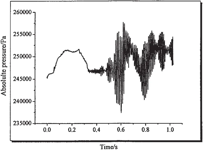
Fig.4 The pressure evolution law in the developing process of cavtiy
where,m is the mass of vehicle,u,v are the translational velocities of vehicle in the body coordinate,r is the pitching angular velocity.xgis the coordinate of gravity center in the direction of x in the body coordinate.Izis the moment of inertia of vehicle.Mzis calculated in simulations.
The kinetic equations are as follows:

In this paper,in order to investigate the planing state of the vehicle without considering any other velocity disturbance,we limit the center of cavitator traveling along the x direction in the ground coordinate,so we assume that:=25m/s,=0m/s,substitute them into equation(10)and combine with equation(9),we finally obtain the equation:

In the following,the planing state is finally obtained by adjusting the location of gravity center xg·xg=0.43m and xg=0.23m.In both conditions,Iz=1.36kg·m2,the mass flow rate is 0.013 456kg/s.The initial state is the same which is shown in Fig.5.

Fig.5 The initial state of pitching motion
The results are shown in Fig.6.

Fig.6 The final state when xg=0.43m
In Fig.7,when xg=0.43m,it can be seen that the vehicle has a pitching angle of nearly 8 degrees when time is 0.27s,and when the drag also has a maximal value.The final state can be seen in Fig.6 which is not allowed for supercavitating vehicles.

Fig.7 The change process of pitching angle and drag coefficient of vehicle when xg=0.43m
Fig.8 shows the vehicle finally has the planing state when xg=0.23m.From Fig.8(a)and(b),it can be seen that when the time is about 0.17s the pitching angle has the biggest value and simultaneously the drag has the maximal value.And when the vehicle enters the planing state,the drag stabilizes gradually.The final planing state is shown in Fig.9.
From the above conclusions,it can be seen that the numerical method in this paper can successfully predict the planing state of supercavitating vehicles and the location of gravity center seriously affects the gesture of vehicle.

Fig.8 The change process of pitching angle and drag of vehicle when xg=0.23m
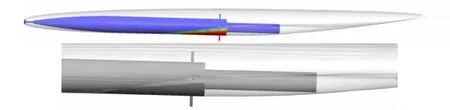
Fig.9 The final planing state when xg=0.23m
5 Conclusions
In this paper,the two fluid multiphase model and DES turbulence model are used to predict the ventilated supercavity.
Firstly,the developing process and the evolution law of supercavity at 25m/s are simulated.The results show that the shedding of cavity results in the pressure fluctuation in cavity,and both phenomena affect each other.The waves intersect at the rear of the cavity,leading to the shedding of cavity.The results show the capability of the numerical method in predicting the ventilated supercavity.
Secondly,the planing state can be obtained using the method provided in this paper and the planing state of supercavitating vehicles is seriously affected by the location of gravity center.
Finally,the numerical method in this paper still should be verified by experiments.Anyway,the accuracy of the method to predict the ventilated supercavity scale and hydrodynamics has been verified by the authors in this paper.
[1]Reichardt H.The laws of cavitation bubbles at axially symmetrical bodies in a flow[R].Minintry of Aifcraft Production,Reports and Translations,1946:766.
[2]Dellanoy Y,Kueny J L.Two-phase flow approach in unsteady cavitation modeling[C]//Cavitation and Multiphase Flow Forum,ASME.New York,ASME-FED,1990,98:153-158.
[3]Coutier-Delgosha O,Reboud J L,Delannoy Y.Numerical simulations in unsteady cavitating flows[J].Numerical Methods Fluids,2003,42:527-548.
[4]Song C,He J.Numerical simulation of cavitating flows by single-phase flow approach[C]//Proc.of 3rd International Symposiumon on Cavitation.Grenoble,1998:295-300.
[5]Yoshinori Saito,Rieko Takami,Ichiro Nakamori.Numerical analysis of unsteady behavior of cloud cavitation around a NACA0015 foil[J].Comput Mech,2007,40:85-96.
[6]Yoshihisa Takekoshi,Takafumi Kawamura.Comparison of cavitation models for simulation of cavitating flow over a hydrofoil[C]//Sixth International Symposium on Cavitation.Wageningen,Netherlands,2006:1-9.
[7]Lindau J W,Kunz R F.High Reynolds number,unsteady,multiphase CFD modeling of cavitation flows[J].Journal of Fluids Engineering,2002,124:606-616.
[8]Yi Shuqun,Zhang Minghui,Zhou Jianwei,Xu Mengmeng,Shong Zhiping,Shen Jiren.Experimental research about the effects of attack angle on supercavitation of restrained model during axial accelerating[J].Chinese Journal of Hydrodynamics,2010,25(3):292-298.
[9]Zhang Jiazhong,Zhao Jing,Wei Yingjie,Wang Cong,Yu Kaiping.Re-entrant jet and its effect on the shape of ventilated supercavity[J].Journal of Ship Mechanics,2010,14(6):571-576.
[10]Li Jitao,Hu Tianqun,He Yousheng.Experimental investigation of supercavitating vehicle motion with oscillatory mode[C]//Proceedings of the Seventh China National Conference on Experimental Fluid Mechanics,2007.
[11]Lee Qitao,Xue Leiping,He Yousheng.Experimental study of ventilated supercavities with a dynamic pitching model[J].Journal of Hydrodynamics,Ser.B,2008,20(4):456-460.
[12]Jiang Zenghui,Yu Kaiping,Wang Cong,Zhang Jiazhong,Huang Wenhu.Experimental research on hydrodynamic character of aft section of underwater supercavitating bodies[J].Engineering Mechanics,2008,25(3):26-30.(in Chinese)
[13]Spalart P R,Jou W H,Strelets M,Allmaras S R.Comments on the feasibility of LES for wings,and on a hybrid RANS/LES approach[C]//1st AFOSR Int.Conf.On DNS/LES,Aug.4-8,1997.Ruston,LA.In Advances in DNS/LES,Liu C&Liu Z Eds.,Greyden Press,Colombus,OH,1997.
[14]Barth T J,Jesperson D C.The design and application of upwind schemes on unstructured meshes[R].AIAA Paper 1989,89-0366.
[15]Semenenko V N.Dynamic processes of supercavitation and computer simulation[C].VKI Special Course on Supercavitating Flows,Brussels:RTO2AVT and VKI,2001.RTO-EN-010(12).
超空泡发展过程研究以及对两种研究滑行力方法的评估
周景军,于开平,张 广
(哈尔滨工业大学,哈尔滨 150001)
采用两流体模型以及DES湍流模型对通气超空泡发展过程以及泡内压力变化规律进行了三维数值仿真。模拟了两种泄气方式:回注射流和双涡管泄气方式。并基于文中数值方法预测通气超空泡方面的能力,对两种研究航行体滑行状态的方法进行了评估:一种方法是在水槽中的定轴俯仰运动,另一种方法是类似于约束模实验的自由俯仰运动,两种方法都采用了网格变形技术。结果表明在相同条件下,后者可以很容易得到超空泡航行体的滑行状态而前者较难获取滑行状态,尽管在水槽中前者更易实现。文中的数值方法可以用来进一步研究滑行状态并给出一些有意义的结论。
通气超空泡;两流体多相流模型;俯仰运动
TV131.2
A
周景军(1981-),男,哈尔滨工业大学教授,博士生;
张 广(1983-),男,哈尔滨工业大学博士生。
TV131.2
A
1007-7294(2011)03-0199-08
date:2010-11-15
Supported by the major National Natural Science Foundation of China(Grant No.10832007)
于开平(1968-),男,哈尔滨工业大学教授;
猜你喜欢
发明与创新·小学生(2021年11期)2021-12-24
上海交通大学学报(2021年8期)2021-09-02
数字海洋与水下攻防(2021年2期)2021-05-08
哈尔滨工业大学学报(2020年1期)2020-12-23
小天使·五年级语数英综合(2018年9期)2018-10-16
哈尔滨工业大学学报(2017年12期)2017-12-12
哈尔滨工业大学学报(2017年9期)2017-11-02
幸福(2016年6期)2016-12-01
工业设计(2016年1期)2016-05-04
工业设计(2016年3期)2016-04-22
- 船舶力学的其它文章
- Comparative Studies of the Transverse Structure Design Wave Loads for a Trimaran by Model Tests and Rule Calculations
- Overview of Upheaval Buckling Theoretical Studies for Submarine Buried Pipeline
- Finite Element Analysis of Delamination Initiation and Growth in E-Glass/Epoxy Reinforced Laminated Beams under Axial Impact
- Numerical Simulations of the Damage Process of Double Cylindrical Shell Structure Subjected to an Impact