大功率并网变流器离散域电流控制策略
王 旭 杨淑英 李 典 张 兴
大功率并网变流器离散域电流控制策略
王 旭 杨淑英 李 典 张 兴
(合肥工业大学可再生能源接入电网技术国家地方联合工程实验室 合肥 230009)
兆瓦级大功率并网变流器的开关频率较低,延迟和离散化误差对控制性能影响较大,导致动态响应慢、电网背景谐波影响大等问题。因此,直接离散域控制系统设计成为必要。该文针对LCL滤波并网变流器建立离散域数学模型,并基于此提出桥臂侧电流和网侧电流融合的离散域电流控制器。同时,为了在不额外增加电流传感器和检测电路的情况下获取并网电流信息,设计电容电压微分器,实现网侧电流的估算,降低硬件复杂性和控制成本。研究表明,该文设计的离散域电流控制器,具有较好的动态性能和电网背景谐波抑制能力。最后,通过硬件在环半实物仿真系统对所提设计进行了实验验证。
LCL型并网变流器 低开关频率 离散域控制 背景谐波
0 引言
相比于单电感L滤波器,高阶LCL滤波器具有较好的谐波衰减特性,尤其在大功率并网变流器场合得到广泛应用。然而,LCL滤波器欠阻尼特性影响了控制系统运行稳定性,增加了电网背景谐波敏感性。串联电阻的无源阻尼方案[1]能够增加阻尼,抑制谐振,但损耗较大,在大功率场合难以应用。为此,基于控制算法的有源阻尼方案受到关注[2-4]。但在数字控制系统中,尤其在大功率应用场合,开关频率较低,采样和控制延迟较大,对有源阻尼甚至系统的实际控制性能的影响随着功率等级的增加而凸显。因此,如何实现大功率LCL型并网变流器的高性能控制是当前研究热点。
文献[5-6]分析了延迟对有源阻尼控制的影响并引入了延迟补偿,提升了系统的阻尼特性,但系统的动态性能仍不足。文献[7-8]分别分析了数字控制延迟对电流环解耦的影响以及对控制带宽的限制。带宽的降低,导致电流动态响应不足,谐波电流增加。文献[9]利用状态观测器对电流进行一拍超前预测,以补偿数字控制延迟影响。参数鲁棒性和系统稳定性影响了状态观测器的效果。文献[10]采用过采样方法、文献[11-12]采用即时采样法减小延迟,但采样易受开关噪声影响,且加载时刻的变化可能会产生多次比较现象。文献[13]通过对反馈电流的延迟补偿,提高了系统的阻尼特性和控制带宽。文献[14]在状态空间控制零极点配置的基础上,引入了相位超前补偿环节,提高了系统的稳定性和动态性能。文献[15-16]进一步直接在离散域中进行零极点配置和延迟补偿,克服了离散化误差影响,使系统动态性能得到进一步提升。实际上,在开关频率较低时,直接针对离散化模型进行控制系统设计,可以将延迟作为控制对象的一部分,从而在控制器设计时作为广义对象加以考虑,有助于控制性能的提升。同时,直接离散域设计也避免了连续域控制器数字化实现时的离散化误差问题。直接基于离散化模型的设计以进一步提升动态性能,仍有较好的研究空间。
当前电网由于大量非线性装置的接入,电网电压中包含有较为丰富的谐波成分[17-18],从而产生并网电流谐波,因此如何提升并网变流器对电网背景谐波扰动的抑制能力也受到关注。文献[19-20]采用多矢量比例积分(Vector Proportional Integral, VPI)控制器,增大谐波频率处控制增益,实现谐波抑制。文献[21]分析了桥臂侧电感电流反馈的间接电流控制技术在谐波抑制方面的不足,提出在多谐振控制器输入端引入电容电流附加补偿回路,从而增强谐波抑制能力。文献[22]在前文基础上进一步利用多二阶广义积分器(Multi-Second-Order Generalized Integrator, MSOGI)提取指定的谐波电流,并引入到控制器输入端,从而既具有桥臂侧电流反馈(Converter Current Feedback, CCF)控制方案优越的稳定性又具有并网电流反馈(Grid Current Feedback, GCF)控制方案优良的谐波抑制能力。多个谐波控制器的并联应用不仅实现复杂,而且稳定性不足。文献[23]采用双环控制,针对桥臂侧电流利用比例积分控制器实现基波无静差跟踪,同时利用比例谐振控制器对并网电流谐波进行抑制,实现基波跟随和谐波抑制。文献[24-25]采用电网电压前馈控制策略,以抑制电网背景谐波对并网电流的影响,但间接离散化设计降低了谐波抑制效果。文献[26]针对工程中常用的利用变压器漏感作为网侧电感的方案难以直接测量电网电压的问题,进一步提出了电容电压全反馈方案。实际上,电网背景谐波对控制系统而言是一种扰动,若能够通过控制器设计提升系统抗扰动能力,则将有助于抑制电网背景谐波对电流的影响。
针对上述大功率LCL型并网变流器电流控制性能依然不足问题,本文提出一种具有高动态性能和强电网背景谐波抑制能力的融合离散状态空间控制方案。相对于文献[15, 23]中的方案而言,本文方案对电流状态反馈进行整体设计,增强了设计的灵活性,有利于控制性能的提升。同时,为节省并网电流传感器和检测电路,简化硬件设计和控制成本,引入了微分器,实现并网电流的估算。
1 并网变流器状态空间模型
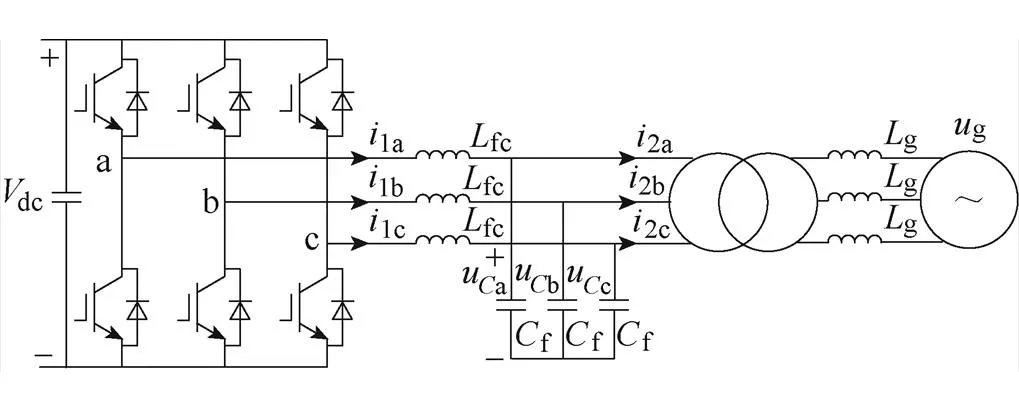
图1 LCL型并网变流器拓扑
1.1 连续域状态空间模型
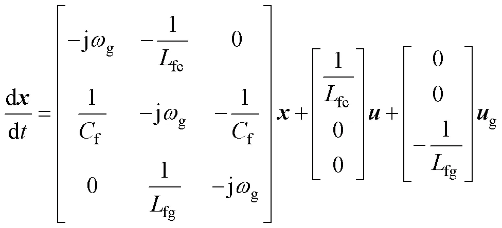
令
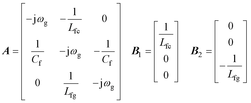
则式(1)状态方程可简化为

1.2 离散域状态空间模型

其中
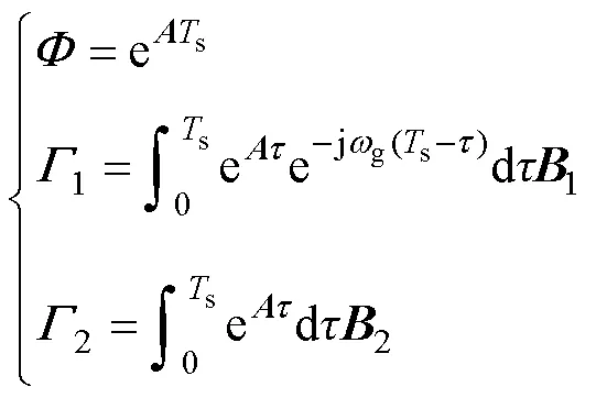
具体表达式如附录第1节所示。
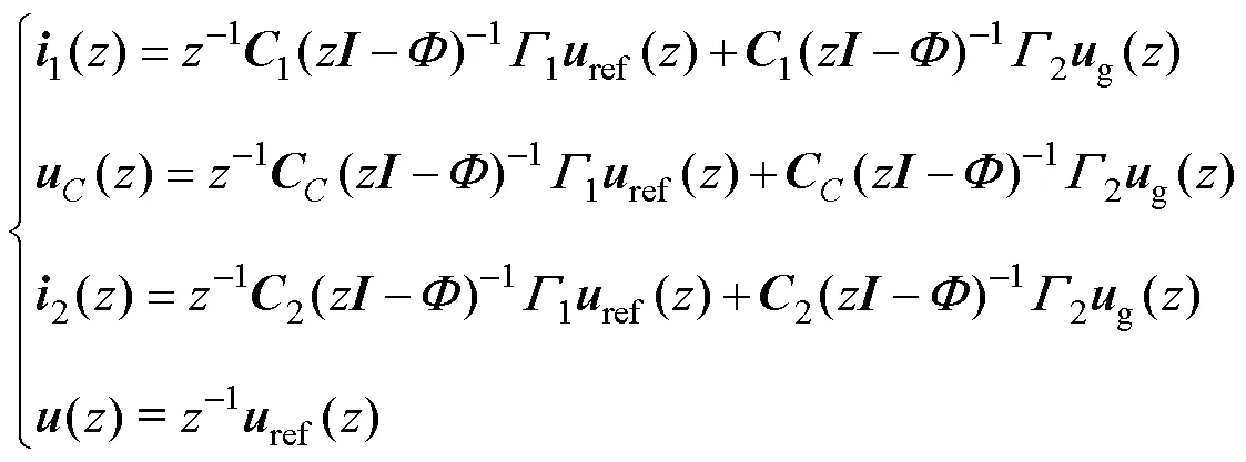
其中

令

则各状态表达式可简记为
2 状态空间融合设计策略
2.1 电流控制方案


式中,、、、与变流器参数有关,具体表达式见附录第1节;控制参数矩阵分别由反馈系数向量和误差控制增益构成,且。式(8)反映了桥臂电流对指令电流的跟随性能。对LCL滤波并网变流器而言,由于电容支路的存在,桥臂电流与并网电流不相等。图3给出了桥臂电流与并网电流关系示意图。流过电容支路的电流主要为谐波电流,包括变流器输出电压形成的谐波电流和电网谐波电压引起的谐波电流。对于前者而言,电容起到滤波作用,能够改善并网电流质量;对于后者而言,电容支路电流会造成并网电流谐波增加,需要加以抑制。LCL滤波器电流回路如图3所示。
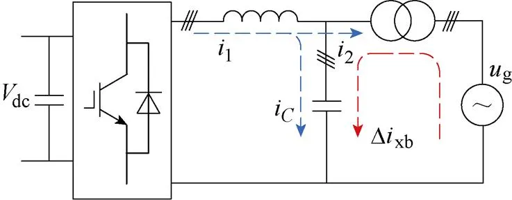
图3 LCL滤波器电流回路

闭环系统特征多项式为

多项式为5阶矩阵,且控制参数矩阵包含5个可设计参数、,理论上可以实现闭环系统极点的任意配置。但对比式(8)和式(9)不难发现,极点的配置不仅影响跟随性能,而且会影响到变流器输出导纳特性。按照主导极点理论,直接决定系统带宽的为主导极点,带宽限制了的配置。图4分别给出了带宽增加时跟随传递函数和输出导纳的幅频响应特性。

如何提升变流器对电网背景谐波干扰的抑制能力成为进一步提高并网变流器性能的关键。文献[15]中的桥臂电流控制方案直接在离散域中进行零极点配置和延迟补偿,使系统动态性能得到大幅提升,但是由于电容支路的存在,难以通过极点配置消除背景谐波对并网电流的影响。文献[23]通过引入并网电流谐波控制环路,能够起到对并网电流谐波的直接控制作用,提升并网电流质量。但是该设计方案缺少控制器的正向一体化设计,整体性能优化受到限制。鉴于此,本文提出了一种融合电流控制方案,能够在系统获得较好动态性能的同时显著提升背景谐波抑制能力。
2.2 状态空间融合控制器

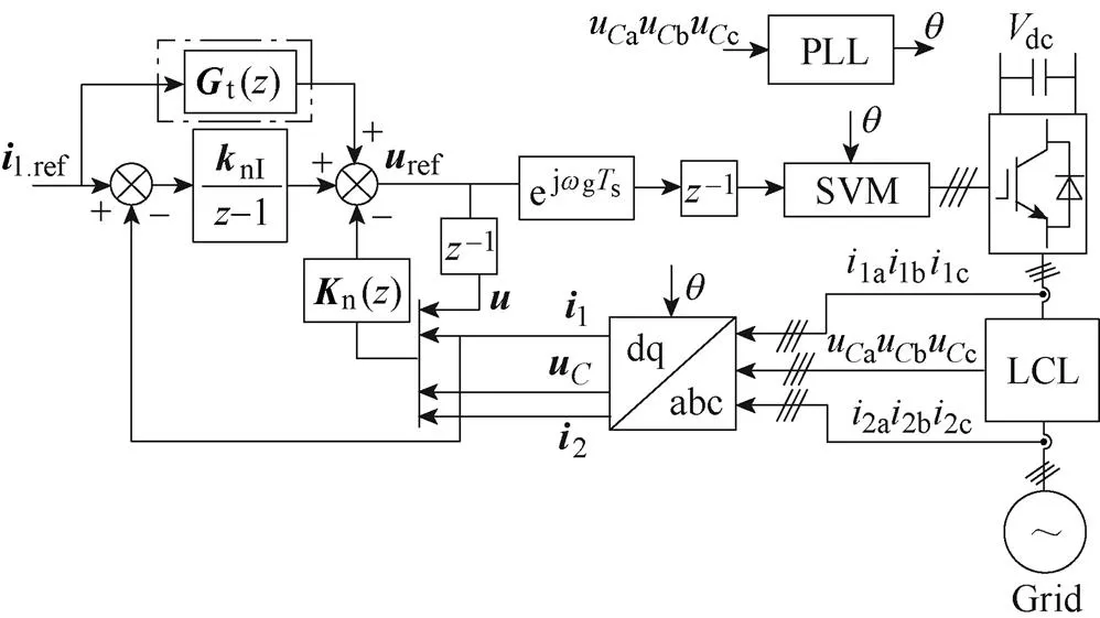
图5 电流控制框图


于是,可将控制输出描述为

将式(12)和式(13)代入式(7)可得图5所示控制方案桥臂电流的跟随传递函数为

此时对应的并网电流的输出导纳为
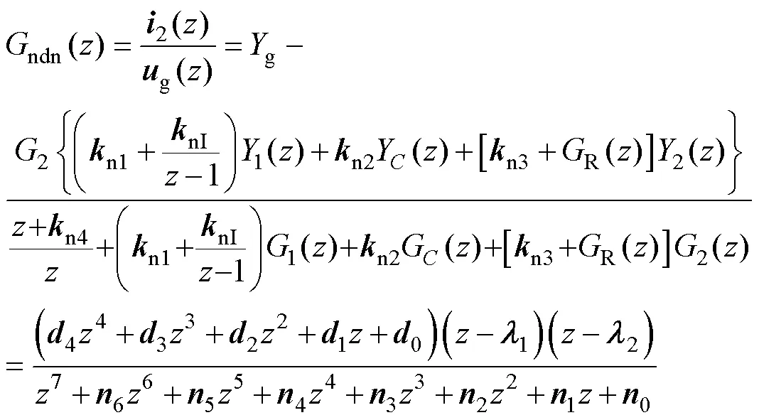

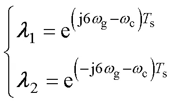

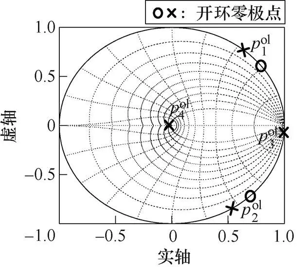
图6 开环传递函数零极点分布

令期望的闭环系统特征多项式为


图7 输出导纳伯德图
在上述极点配置的情况下,式(14)可化简为

为此,本文将传统的比例前馈环节修改为

将式(13)与式(20)代入式(7)中可得

其中
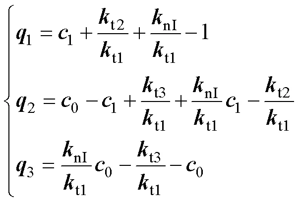

令

则最终本文方案的跟随传递函数为

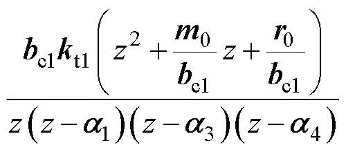
综上所述,由式(15)和式(24)可以发现:上述改进的前馈补偿环节可以较好地提升系统的跟随性能,但不影响系统的输出导纳特性。
2.3 电流估算
由于实际系统采集电容电压进行锁相的特殊结构,因此考虑利用微分器,根据电容电压对并网电流进行估计,降低硬件复杂性和控制成本。
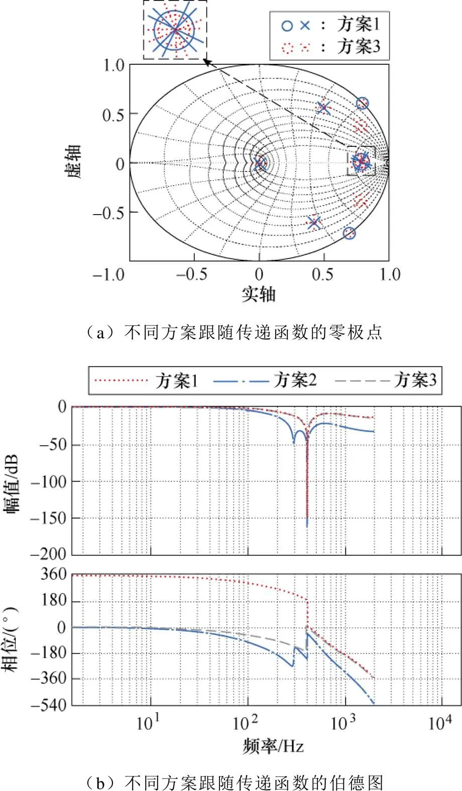
图8 不同方案的跟随传递函数的零极点和伯德图
文献[3-4]较为完整地介绍了目前微分器设计的方法,因此本文直接在离散域中设计微分器。
针对理想微分“”采用后向欧拉法对其离散化,得到表达式为


将式(25)与式(26)相乘,构造出基于后向欧拉和一阶超前补偿的微分器,其表达式为


图10 微分器的伯德图
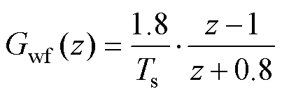
因此估算并网电流表达式为

为了分析电流估算对控制方案性能的影响,这里将基于电流估算的方案命名为方案4。图11为方案4对应的控制框图。
图12中给出了不同方案的跟随传递函数和输出导纳伯德图。由图12可以看出,微分环节的使用几乎不影响系统的跟随响应曲线,仍具有较快的跟随性能。且不难发现:相对于采集并网电流而言,采用估算并网电流,输出导纳有所增大,对背景谐波抑制能力有所降低,但仍然较强。
3 仿真证明
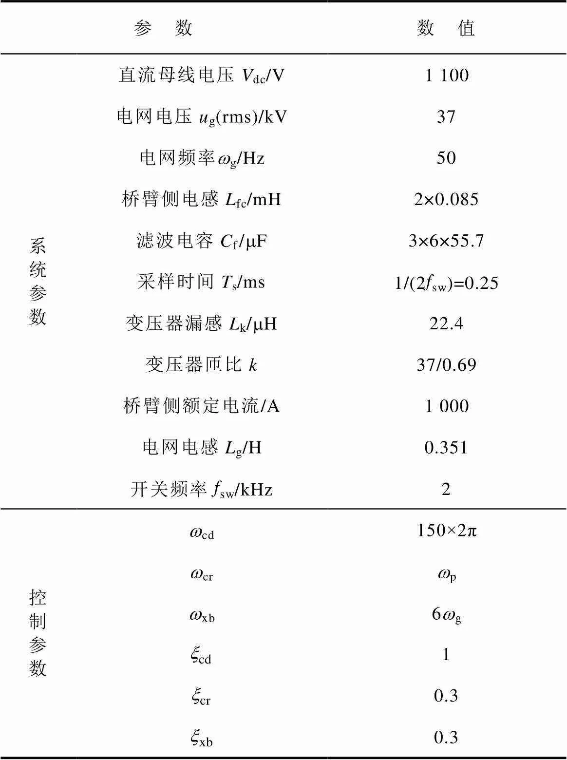
为了对上述融合离散状态空间控制方案进行验证和对比,本文搭建了Matlab/Simulink仿真模型,仿真参数见表1。为了反映工程实际情况,本文系统参数选用某型号MW级并网变流器参数。
表1 MW级并网变流器参数
Tab.1 MW-class grid-side converter parameters

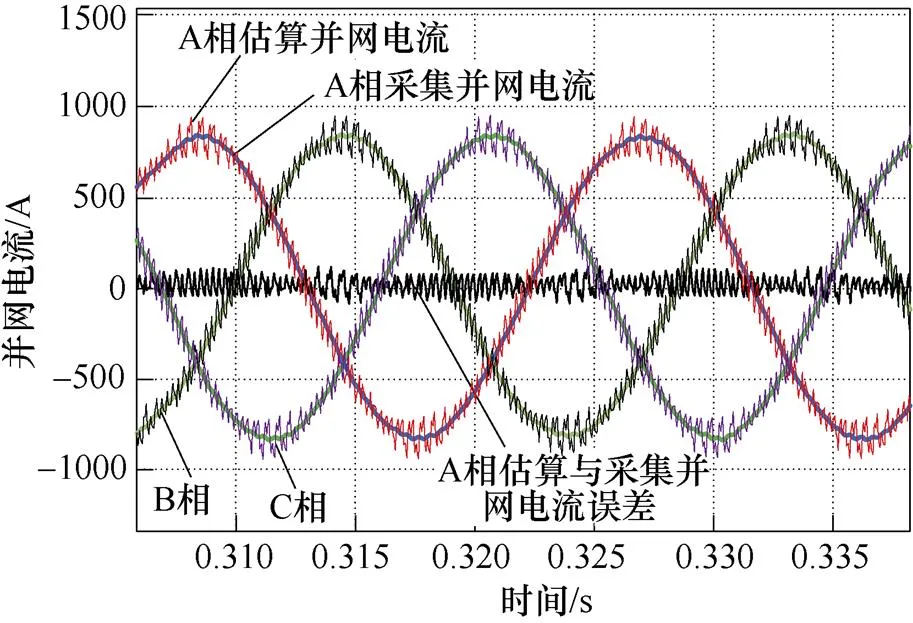
图13 估算和采集并网电流的波形
3.1 跟随性能对比
图14为电流指令发生阶跃变化时不同方案对应的桥臂侧dq轴电流仿真波形。由图14c可以看出,方案4的电流上升时间约为4.5 ms,且几乎没有超调,与图14a中方案1的跟随波形几乎一致,而图14b中方案2的电流上升时间约为7.5 ms。正如2.2节分析一样,方案4通过改进前馈补偿环节,保持了方案1近似一阶系统的跟随性能,虽然微分环节的使用造成期望零极点的偏移,但最终跟随响应曲线几乎保持一致,具有较好的动态跟随性能。
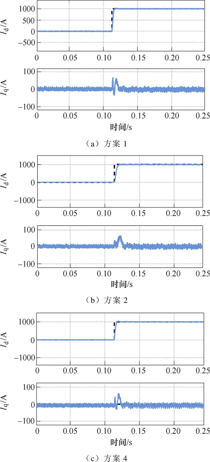
图14 阶跃变化时不同方案的电流仿真波形
3.2 抗扰性能对比
3.2.1 电网电压骤降
图15为0.11 s发生40 %电网电压骤降时不同方案对应的dq轴电流波形。不难发现方案2、4与方案1具有近乎相同的抗电网电压阶跃变化能力,由图15b和图15c可以看出,方案2和4对于阶跃性干扰可以在10 ms内恢复,与图15a中方案1的恢复时间相比,几乎一致,这一点也可以由图12b中0 Hz处幅频特性看出,使2.3节理论分析得到验证。
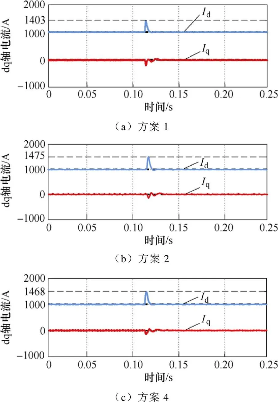
图15 电网电压骤降时不同方案的电流仿真波形
3.2.2 电网电压背景谐波影响
图16为0.3 s后电网电压注入6 %的5、7次谐波前后对应的并网电流波形。由图16a可以看出,并网电流发生畸变,此时对应的总谐波畸变率(Total Harmonic Distortion, THD)为15.91 %,已远远超过并网标准的5 %。表明方案1对于电网电压背景谐波的抑制能力不足,这一点与图12幅频特性分析一致。而图16b所示的方案2与图16c所示的方案3和图16d所示的方案4所获得的电流波形没有明显畸变,对应的电流THD分别为1.33 %、1.35 %和1.68 %,这也与图12中的幅频响应结果一致。表明本文设计的融合电流控制方案,在保留快速电流动态响应能力的同时,有效地提升了电网背景谐波的抑制能力。

图16 电网电压畸变时不同方案的电流仿真波形
3.3 参数敏感度分析

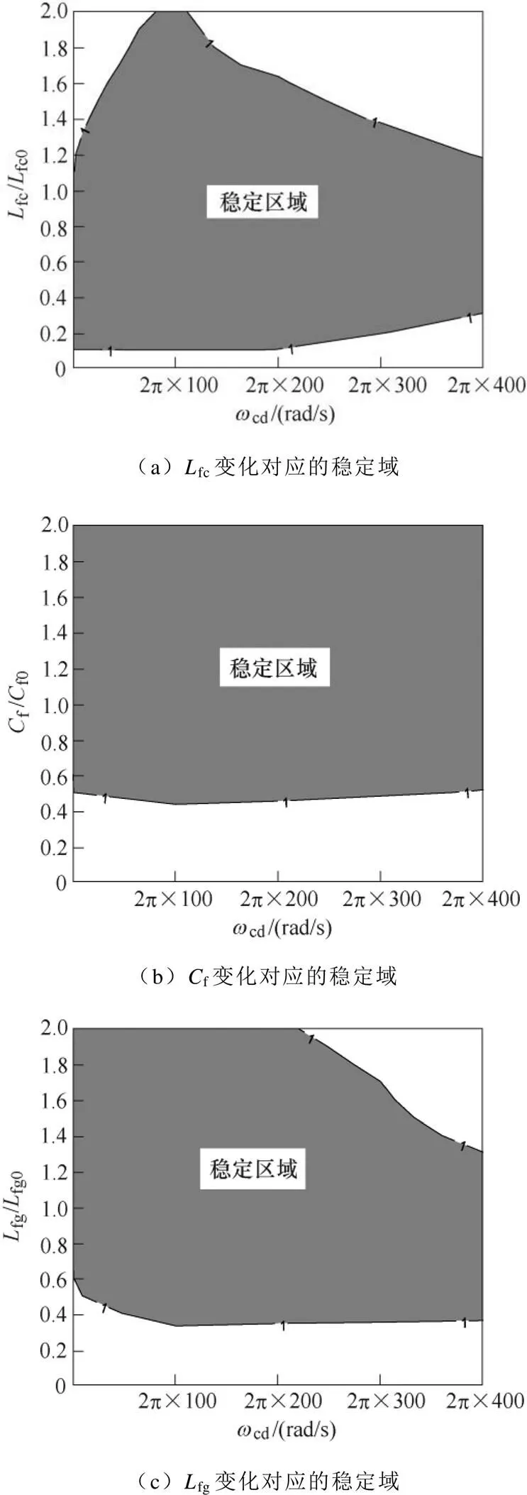
图17 参数变化的稳定
4 实验验证

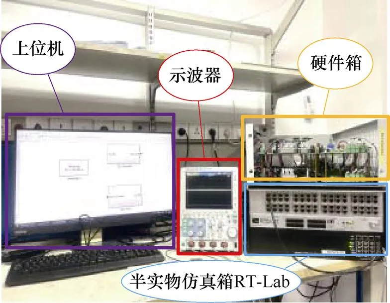
图18 半实物实验框图

图19 半实物实验平台
4.1 动态性能
图20记录了在电流参考值发生1 000 A的阶跃变化时桥臂侧电流的动态响应过程。可以看出:方案4与方案1的电流响应波形几乎保持一致,具有较快的动态性能,且明显快于方案2。

图20 阶跃变化时不同方案的电流实验波形
4.2 电网扰动响应
实验评估了本文方案在电网电压骤降和畸变时的抗扰性能。
4.2.1 电网电压骤降
图21为电网电压发生0.4(pu)骤降时的电流响应。与理论分析和仿真一致,方案2的动态性能不足,但和方案4一样都具有较好的抗阶跃扰动抑制能力。
4.2.2 电网电压谐波

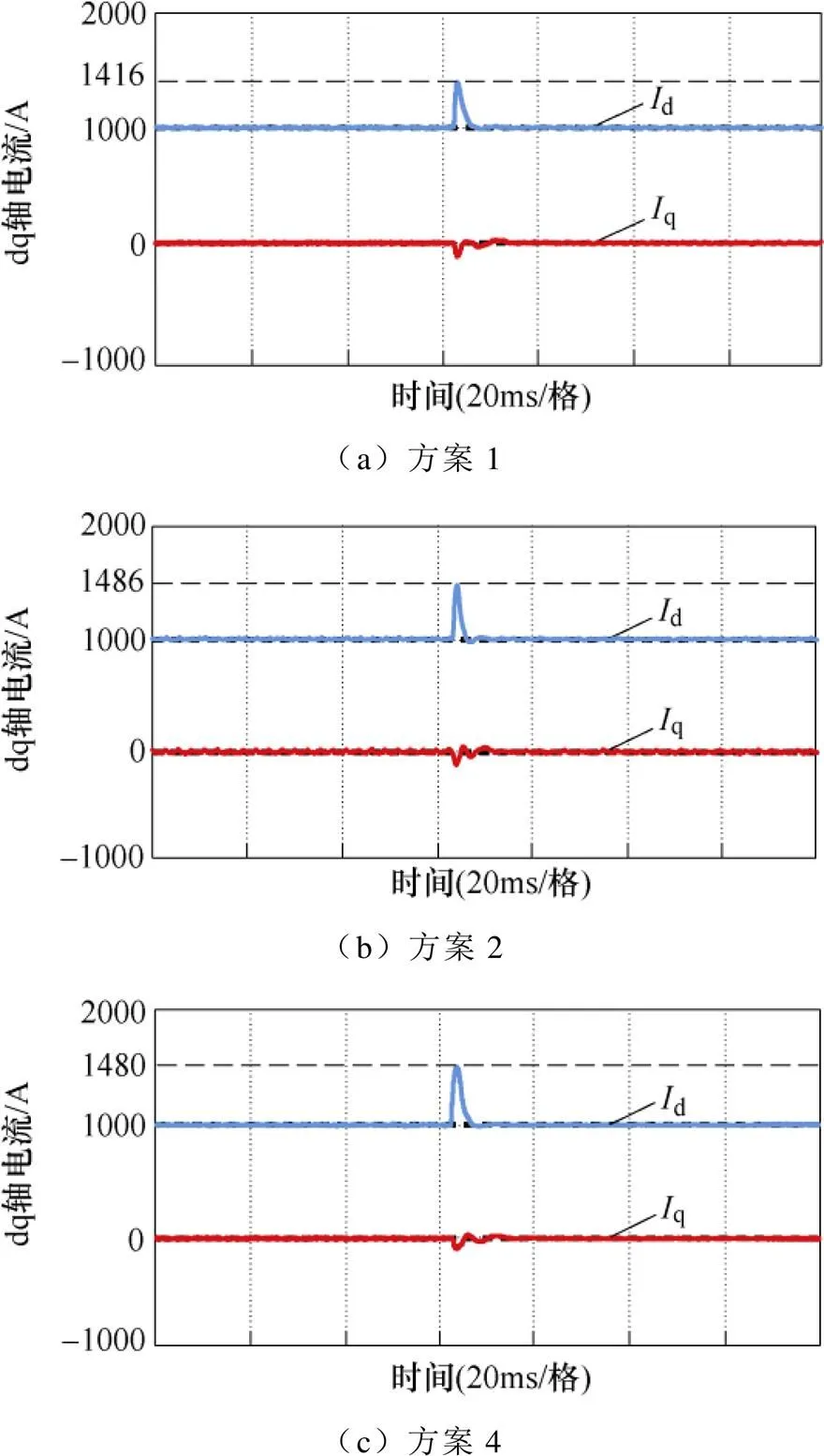
图21 电网电压骤降时不同方案的电流实验波形
4.3 稳定运行范围
图23中记录了实际滤波器参数发生变化时方案4的运行性能。由图可以看出,当实际桥臂侧电感参数、滤波电容参数以及网侧电感参数发生一定范围的变化时,系统仍稳定运行。这与图17中关于稳定性的分析一致。
5 结论
本文提出一种融合离散状态空间控制方案,用于大功率LCL并网变流器的电流控制。基波和谐波回路的融合设计简化了设计复杂性,提升了设计优化自由度。同时,微分器的使用节省了并网电流的检测,降低了硬件的复杂性和控制成本。本文分析了零极点影响,并基于零极点配置实现了控制器参数的优化设计。对比分析了微分器引入前后的控制性能,讨论了参数鲁棒性。最后,通过仿真和硬件在环实验对其分析和设计进行了验证。研究表明,本文所设计的控制方案,在保留较好的动态响应性能的同时,能够明显提升对电网背景谐波扰动的抑制能力,提升了并网电流质量。
1. 零阶保持离散化模型如下:
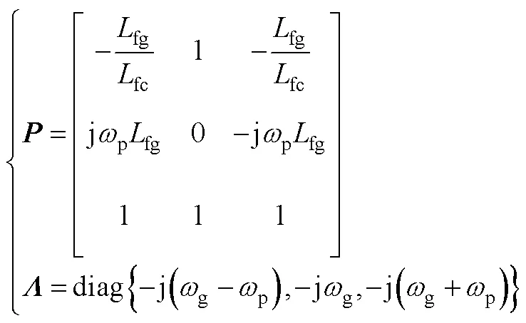
其中
因此

具体表达式为
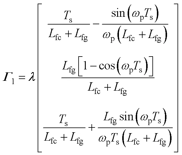
进一步可得


其中

为了方便表述,设计辅助参数如下
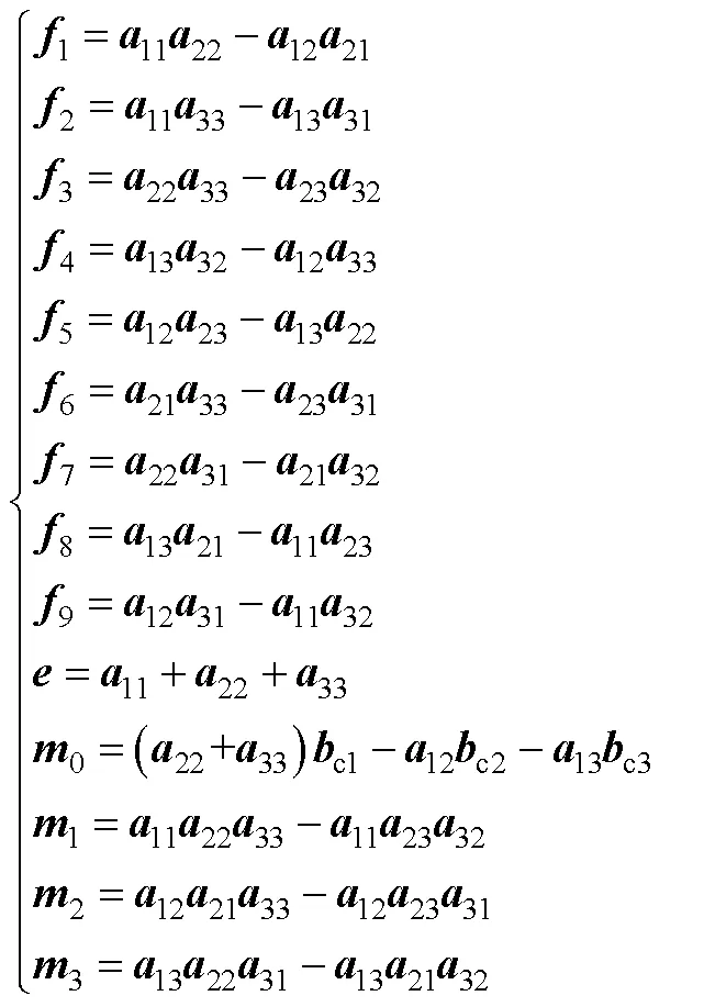
进一步设计辅助参数如下
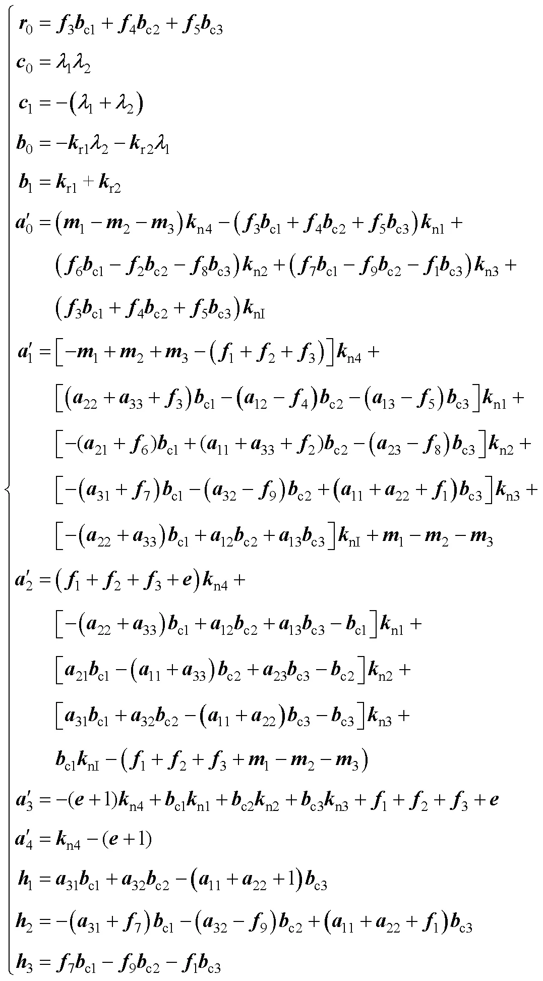
因此

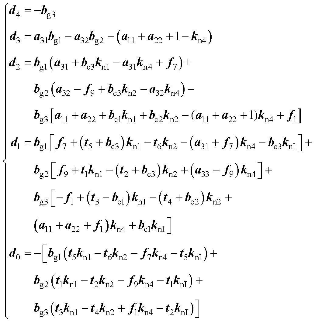
为了方便表述,设计辅助参数如下
因此
[1] Sharma H R, Suryawanshi H M, Chaturvedi P, et al. Implementation of passive damping technique in LCL filter for three-phase grid connected inverter[C]//2022 IEEE 2nd International Conference on Sustainable Energy and Future Electric Transportation (SeFeT), Hyderabad, India, 2022: 1-6.
[2] Li Xiaoqiang, Wu Xiaojie, Geng Yiwen, et al. Wide damping region for LCL-type grid-connected inverter with an improved capacitor-current-feedback method[J]. IEEE Transactions on Power Electronics, 2015, 30(9): 5247-5259.
[3] Xin Zhen, Loh P C, Wang Xiongfei, et al. Highly accurate derivatives for LCL-filtered grid converter with capacitor voltage active damping[J]. IEEE Transactions on Power Electronics, 2016, 31(5): 3612-3625.
[4] Pan Donghua, Ruan Xinbo, Wang Xuehua. Direct realization of digital differentiators in discrete domain for active damping of LCL-type grid-connected inver- ter[J]. IEEE Transactions on Power Electronic, 2018, 33(10): 8461-8473.
[5] Chen Chen, Xiong Jian, Wan Zhiqiang, et al. A time delay compensation method based on area equiva- lence for active damping of an LCL-type converter[J]. IEEE Transactions on Power Electronics, 2017, 32(1): 762-772.
[6] 方天治, 黄淳, 陈乃铭, 等. 一种提高弱电网下LCL型并网逆变器鲁棒性的相位超前补偿策略[J]. 电工技术学报, 2018, 33(20): 4813-4822.
Fang Tianzhi, Huang Chun, Chen Naiming, et al. A phase-lead compensation strategy on enhancing robustness of LCL-type grid-tied inverters under weak grid conditions[J]. Transactions of China Elec- trotechnical Society, 2018, 33(20): 4813-4822.
[7] 张森, 赵剑锋, 刘康礼, 等. 数字控制延时对电流环解耦有效性的影响[J]. 电工技术学报, 2020, 35(增刊2): 484-493.
Zhang Sen, Zhao Jianfeng, Liu Kangli, et al. Research on the impacts of digital control delay on the effectiveness of current loop decoupling[J]. Transa- ctions of China Electrotechnical Society, 2020, 35(S2): 484-493.
[8] Dannehl J, Liserre M, Fuchs F W. Filter-based active damping of voltage source converters with LCL filter[J]. IEEE Transactions on Industrial Electronics, 2011, 58(8): 3623-3633.
[9] Nussbaumer T, Heldwein M L, Gong Guanghai, et al. Comparison of prediction techniques to compensate time delays caused by digital control of a three-phase Buck-type PWM rectifier system[J]. IEEE Transa- ctions on Industrial Electronics, 2008, 55(2): 791- 799.
[10] Corradini L, Stefanutti W, Mattavelli P. Analysis of multi-sampled current control for active filters[C]// 2007 IEEE Industry Applications Annual Meeting, New Orleans, LA, USA, 2007: 1608-1615.
[11] 潘冬华, 阮新波, 王学华, 等. 提高LCL型并网逆变器鲁棒性的电容电流即时反馈有源阻尼方法[J]. 中国电机工程学报, 2013, 33(18): 1-10, 21.
Pan Donghua, Ruan Xinbo, Wang Xuehua, et al. A capacitor-current real-time feedback active damping method for improving robustness of the LCL-type grid-connected inverter[J]. Proceedings of the CSEE, 2013, 33(18): 1-10, 21.
[12] Pan Donghua, Ruan Xinbo, Bao Chenlei, et al. Capacitor-current-feedback active damping with reduced computation delay for improving robustness of LCL-type grid-connected inverter[J]. IEEE Transa- ctions on Power Electronics, 2013, 29(7): 3414-3427.
[13] 王林, 孙鹏菊, 薛统宇, 等. 一种提高LCL型并网逆变器电流控制性能的延时补偿方法[J]. 中国电机工程学报, 2020, 40(19): 6320-6330.
Wang Lin, Sun Pengju, Xue Tongyu, et al. A delay compensation method to improve the current control performance of the LCL-type grid-connected inver- ter[J]. Proceedings of the CSEE, 2020, 40(19): 6320- 6330.
[14] Kukkola J, Hinkkanen M. Observer-based state-space current control for a three-phase grid-connected converter equipped with an LCL filter[J]. IEEE Transactions on Industry Applications, 2014, 50(4): 2700-2709.
[15] Kukkola J, Hinkkanen M, Zenger K. Observer-based state-space current controller for a grid converter equipped with an LCL filter: analytical method for direct discrete-time design[J]. IEEE Transactions on Industry Applications, 2015, 51(5): 4079-4090.
[16] Pérez-Estévez D, Doval-Gandoy J, Yepes A G, et al. Positive- and negative-sequence current controller with direct discrete-time pole placement for grid-tied converters with LCL filter[J]. IEEE Transactions on Power Electronics, 2017, 32(9): 7207-7221.
[17] 陈杰, 章新颖, 闫震宇, 等. 基于虚拟阻抗的逆变器死区补偿及谐波电流抑制分析[J]. 电工技术学报, 2021, 36(8): 1671-1680.
Chen Jie, Zhang Xinying, Yan Zhenyu, et al. Dead- time effect and background grid-voltage harmonic suppression methods for inverters with virtual impedance control[J]. Transactions of China Elec- trotechnical Society, 2021, 36(8): 1671-1680.
[18] 林丽娟, 贾清泉, 田书娅, 等. 基于一致性算法的配电网谐波分布式治理策略[J]. 电力系统自动化, 2022, 46(2): 109-117.
Lin Lijuan, Jia Qingquan, Tian Shuya, et al. Distributed harmonic mitigation strategy of dis- tribution network based on consensus algorithm[J]. Automation of Electric Power Systems, 2022, 46(2): 109-117.
[19] 游小杰, 杨才伟, 王剑, 等. 一种适用于机车PWM整流器的比例积分-谐振电流控制器设计[J]. 电工技术学报, 2021, 36(23): 4926-4936.
You Xiaojie, Yang Caiwei, Wang Jian, et al. A tuning method for proportional integral-resonant current controller in locomotive PWM rectifiers[J]. Transa- ctions of China Electrotechnical Society, 2021, 36(23): 4926-4936.
[20] 黄仁志, 全相军, 吴在军, 等. 基于多重谐振控制器的参考值前馈自适应控制[J]. 电工技术学报, 2022, 37(16): 4212-4224.
Huang Renzhi, Quan Xiangjun, Wu Zaijun, et al. A multiple resonant based on reference feedforward adaptive voltage control of three-phase inverter[J]. Transactions of China Electrotechnical Society, 2022, 37(16): 4212-4224.
[21] Xin Zhen, Mattavelli P, Yao Wenli, et al. Mitigation of grid-current distortion for LCL-filtered voltage- source inverter with inverter-current feedback con- trol[J]. IEEE Transactions on Power Electronics, 2018, 33(7): 6248-6261.
[22] Zhao Rende, Li Qian, Xu Hailiang, et al. Harmonic current suppression strategy for grid-connected PWM converters with LCL filters[J]. IEEE Access, 2019, 7: 16264-16273.
[23] 谢震, 汪兴, 张兴, 等. 基于谐振阻尼的三相LCL型并网逆变器谐波抑制优化策略[J]. 电力系统自动化, 2015, 39(24): 96-103.
Xie Zhen, Wang Xing, Zhang Xing, et al. Optimized harmonic suppression strategy of grid-connected inverter with an LCL-type filter based on resonance damping[J]. Automation of Electric Power Systems, 2015, 39(24): 96-103.
[24] 徐健, 曹鑫, 郝振洋, 等. 基于电网谐波电压前馈的虚拟同步整流器电流谐波抑制方法[J]. 电工技术学报, 2022, 37(8): 2018-2029.
Xu Jian, Cao Xin, Hao Zhenyang, et al. A harmonic- current suppression method for virtual synchronous rectifier based on feedforward of grid harmonic voltage[J]. Transactions of China Electrotechnical Society, 2022, 37(8): 2018-2029.
[25] Li Weiwei, Ruan Xinbo, Pan Donghua et al. Full- feedforward schemes of grid voltages for a three- phase LCL-type grid-connected inverter[J]. IEEE Transactions on Industrial Electronics, 2013, 60(6): 2237-2250.
[26] Zhang Hao, Ruan Xinbo, Lin Zhiheng, et al. Capacitor voltage full feedback scheme for LCL-type grid-connected inverter to suppress current distortion due to grid voltage harmonics[J]. IEEE Transactions on Power Electronics, 2021, 36(3): 2996-3006.
[27] Franklin G F, Powell J D, Workman M L. Digital control of dynamic systems[M]. Menlo Park, CA, USA: Addison-Wesley, 1997.
[28] Hu Mingjin, Hua Wei, Ma Guangtong, et al. Improved current dynamics of proportional-integral-resonant controller for a dual three-phase FSPM machine[J]. IEEE Transactions on Industrial Electronics, 2021, 68(12): 11719-11730.
Discrete-Time Domain Current Control Strategy for High Power Grid-Connected Converters
(National and Local Joint Engineering Laboratory for Renewable Energy Access to Grid Technology Hefei University of Technology Hefei 230009 China)
For high-power grid-connected converters, the switching frequency usually is low. Consequently, the adverse effects enforced by the control delay and discretizing errors are heavy. However, traditional current control strategies generally ignore these effects, reducing the performance of the designed controller. Recently, some strategies were presented to compensate for the control delay and the discretizing errors. However, most suffer from low dynamic response and high sensitivity to the power grid harmonics. Therefore, a current control strategy combining the bridge arm-side and the grid-side currents is designed directly in the discrete-time domain, and pole-zero placement is used in synchronous coordinates. Meanwhile, a differentiator to the capacitor voltageis introduced to estimate the grid-side currents.Consequently,hardware complexity and the corresponding control cost are reduced.
The discrete-time model of the converter with LCL is built in synchronous coordinates as the output filter, including the computational delay, firstly. The corresponding structure of the combined state-space control scheme is as follows: the harmonic control loop of the grid-side currents is constructed and combined with the fundamental current control loop on the bridge arm-side using the full state-feedback control. And then, the integral controller is introduced for improved disturbance rejection, and the reference-feedforward controller is designed to increase the reference-tracking dynamic performance. Consequently, the closed-loop transfer function of the system is obtained based on the discrete-time model and the control scheme. Then the state feedback function matrix and the feedforward module are optimized based on the pole-zero placement. Finally, a differentiator is introduced to estimate the grid-side currents, reducing the hardware cost.
Experiment results based on a hardware-in-loop simulator show that the response time of the bridge arm-side currents to a 1 000 A step-up change is about 4.5 ms; the recovery time of the bridge arm-side currents facing a grid-voltage dip of 0.4(pu) is about 10ms; and the total harmonic distortion of the grid-side currents is 2.28 %, below the 5 % limit given in standards, in the circumstances of 6 % fifth and seventh harmonic components appearing in the grid voltage. Finally, to verify the robustness of the proposed strategy to the parameter deviations, the actual system parameters are deviated artificially from their nominal values. The results show that the proposed strategy can operate satisfactorily in the range of ±40 % parameter deviations, and the influence of the parameter deviations is low.
The following conclusions can be drawn from the experiment results: (1) Compared with the typical discrete-time state-space control strategy, the proposed strategy keeps the same dynamic performance while improving the capability of rejecting the grid harmonic disturbance. (2) The proposed control strategy simplifies the design complexity based on the direct pole-zero placement and increases freedom degrees by combining the design of fundamental current and harmonic control loops. (3) The differentiator to the capacitor voltage is designed to acquire grid-side currents without additional current sensors and the corresponding sampling circuit, reducing the hardware complexity and the cost.
Grid-connected converter with LCL, low switching frequency, discrete-time control, grid harmonics
安徽省科技重大专项资助项目(202003a05020029)。
2022-12-13
2023-01-13
10.19595/j.cnki.1000-6753.tces.222309
TM464
王 旭 男,1998年生,硕士研究生,研究方向为大功率风电变流器电流控制。E-mail: wx1998_wangxu@163.com
杨淑英 男,1980年生,教授,博士生导师,研究方向为风力发电系统和电驱动系统。E-mail: yangsyhfah@163.com(通信作者)
(编辑 陈 诚)

