Limit state analysis of rigid retaining structures against seismically induced passive failure in heterogeneous soils
Jinfeng Zhou,Chngbing Qin
a College of Civil Engineering, Huaqiao University, Xiamen, 362021, China
b School of Civil Engineering, Chongqing University, Chongqing, 400045, China
c Key Laboratory of New Technology for Construction of Cities in Mountain Area, Chongqing University, Chongqing, 400045, China
d National Joint Engineering Research Center of Geohazards Prevention in the Reservoir Areas, Chongqing University, Chongqing, 400045, China
Keywords: Retaining wall Passive earth pressure Earthquakes Finite-element limit-analysis methods
ABSTRACT Soils are not necessarily uniform and may present linearly varied or layered characteristics,for example the backfilled soils behind rigid retaining walls.In the presence of large lateral thrust imposed by arch bridge,passive soil failure is possible.A reliable prediction of passive earth pressure for the design of such wall is challenging in complicated soil strata,when adopting the conventional limit analysis method.In order to overcome the challenge for generating a kinematically admissible velocity field and a statically allowable stress field,finite element method is incorporated into limit analysis,forming finiteelement upper-bound (FEUB) and finite-element lower-bound (FELB) methods.Pseudo-static,original and modified pseudo-dynamic approaches are adopted to represent seismic acceleration inputs.After generating feasible velocity and stress fields within discretized elements based on specific criteria,FEUB and FELB formulations of seismic passive earth pressure (coefficient KP) can be derived from work rate balance equation and stress equilibrium.Resorting to an interior point algorithm,optimal upper and lower bound solutions are obtained.The proposed FEUB and FELB procedures are well validated by limit equilibrium as well as lower-bound and kinematic analyses.Parametric studies are carried out to investigate the effects of influential factors on seismic KP.Notably,true solution of KP is well estimated based on less than 5% difference between FEUB and FELB solutions under such complex scenarios.
1.Introduction
There are some conditions in practice where lateral pressures are generated to push soils.When a retaining wall experiences certain displacements to reach a limit equilibrium state,such lateral pressure corresponds to passive earth pressure beyond which soils would undergo passive failure.Comparatively,a much larger displacement is required for a retaining wall to reach its passive limit state,in contrast to active case.Nonetheless,such passive failure is also possible under large lateral pressures,for example,in the abutment of arch bridges.Apart from physical modelling,limit analysis is capable of providing rigorous upper and lower bounds to passive earth pressure analysis,and due to its efficacy,it is selected as the principal method used in this study,aiming to obtain the true solution at limit state.
Within the framework of plasticity theory,limit analysis consists of lower-and upper-bound theorems based on which true solution for the problem of interest can be well limited to a range of lower-and upper-bound solutions.It is worthwhile pointing out that it is challenging to perform a complete limit analysis due to the construction of a kinematically admissible velocity field and a statically allowable stress field,particularly in non-uniform soils.For simplification,preliminary studies were principally performed for homogeneous and isotropic soils (Chen,1975;Chen and Liu,1990),where linear Mohr-Coulomb (MC) criterion was adopted for calculating static and seismic passive earth pressures.Thereafter,some researchers(e.g.Soubra,2000;Liu et al.,2018;Yang and Li,2018;Li and Yang,2019a,2019b;Li et al.,2020) computed passive and active earth pressures acting on rigid retaining walls,from the perspective of upper bound theorem.In contrast,a lower bound analysis was carried out for evaluation of passive earth pressure in a homogeneous soil(Lancellotta,2007).In order to account for nonuniform soils,some techniques are necessitated for this specific purpose.For example,Qin and Chian (2020) proposed a discretization-based kinematic analysis procedure and combined the merits of discretization technique and upper-bound analysis to investigate pseudo-static and pseudo-dynamic passive earth pressures,in considerations of non-uniform soils.Definitely,finiteelement upper-bound (FEUB) analysis is capable of considering almost all scenarios including non-uniform soil parameters,in the analysis of passive earth pressures.Note that in the study of Shiau et al.(2008),however,such powerful method was applied to evaluate passive earth pressures,merely accounting for uniform and cohesionless soils,without providing lower bound solutions.In contrast,a finite-element lower-bound (FELB) analysis was only performed in Fathipour et al.(2020,2021)to evaluate lateral earth pressures by virtue of second-order cone programming.In the above literature,FEUB and FELB procedures were separately applied to assess passive earth pressures specific to limited scenarios,which is not the case in slope stability analysis where both upper-and lower-bound solutions were calculated(Oberhollenzer et al.,2018;Ukritchon and Keawsawasvong,2018;Qin and Zhou,2023;Zhou and Qin,2023).Therefore,in order to estimate the true solution of seismic passive earth pressure,FEUB and FELB procedures are adopted and developed,which is the motivation of this study.
It is acknowledged that earthquake is a major trigger for engineering failure,including for retaining walls.Selection of earthquake inputs is imperative for accurate prediction of lateral earth pressures.Apart from the commonly used pseudo-static approach,pseudo-dynamic approach is mainly adopted in this study.Such approach provides a compromise between accurate but complex acceleration time-history and simple but approximate pseudostatic approach.The original pseudo-dynamic approach was proposed by Steedman and Zeng(1990),in order to represent a linearly varied horizontal acceleration when shear wave propagates along a retaining wall.This aids to mimic tempo-spatial earthquake effects.Thereafter,some authors adopted such approach to further estimate passive earth pressures,by means of limit equilibrium only(e.g.Choudhury and Nimbalkar,2005;Nimbalkar and Choudhury,2007).Note that,however,violation of zero stress boundary conditions at the ground surface exists in the original pseudo-dynamic approach.The modified pseudo-dynamic approach was accordingly developed to incorporate the spectral characteristics of site response analysis,so as to overcome such main drawback.The modified approach can also account for soil damping properties and nonlinearly varied acceleration with depth.It was then applied to investigate lateral earth pressures with limit equilibrium(Rajesh and Choudhury,2017;Srikar and Mittal,2020),method of stress characteristics (Santhoshkumar and Ghosh,2020),as well as discretization-based upper bound analysis (Qin and Chian,2020)and FELB analysis(Fathipour et al.,2020,2021).Based on the above studies,true solution of passive earth pressure is still difficult to be estimated.
In this study,the core work is to develop dynamic FEUB and FELB procedures for the assessment of seismic passive earth pressure of backfilling soils on a rigid retaining wall,incorporating the modified pseudo-dynamic approach.Meanwhile,a linear variation in soil cohesion and friction angle is also incorporated in the procedures to encompass wider scenarios.Rigorous lower-and upperbound solutions are calculated under complicated conditions,and based on which true solution of passive earth pressure is to be better estimated.Effects of influential factors on FEUB and FELB solutions and critical failure mechanisms are investigated to show its implication on the design of a retaining wall in earthquakeprone regions.
2.Problem description
This study is to investigate passive earth pressures of backfilling soils acting on a rigid retaining wall.Such wall is characterized by heightH,and an inclination angle of λ,as illustrated in Fig.1.When wall friction is considered,passive earth pressures are inclined at an angle of δw(wall friction angle)with respect to the outward-drawn normal direction of the wall.In this study,a linearly increased MC soil strength profile is considered,with soil cohesion (ch) and friction angle (φh) at ground surface linearly increased toc0and φ0at wall base level.Note that boundary conditions must be satisfied,including zero velocity on vertical side boundaries and model bottom in FEUB analyses,and zero stress on ground surface in the absence of surface surcharge in FELB analyses.It is worthwhile highlighting that along wall back,unknown normal and shear stresses induced by passive earth pressures are exerted on backfilling soils in FELB analyses so as to meet stress equilibrium conditions at such boundary.In order to avoid boundary effects,a relatively large model is established.
3.Methodologies
3.1.Pseudo-dynamic earthquake methods
In the presence of an earthquake,a proper manner to characterize earthquake inputs directly affects the accuracy of lateral earth pressures.For comparison,the simplified pseudo-static approach (P-s),original pseudo-dynamic approach (P-d),and modified pseudo-dynamic approach (MP-d) are considered.In the P-s analysis,the horizontal and vertical seismic forces (accelerations) keep constant,to provide a quick estimate (Qin and Chian,2020).Specific introduction of the P-d approach can be found in Qin and Chian (2018,2019) where the magnitude of seismic accelerations varies linearly with depth by virtue of a constant amplification factorf,and the initial phase difference between horizontal and vertical accelerations is considered as zero in this study.The MP-d approach provides another way to consider earthquake inputs from the perspective of seismic response of soil displacement.By means of double differential of soil displacement,horizontal and vertical seismic accelerations are derived,satisfying the equation of motion of stress waves and boundary conditions.For discussion,the expressions of horizontal and vertical seismic accelerations (ah(t,y)andav(t,y)) at timetand positionyare shown as below:
wherekhis the seismic horizontal coefficient at wall base,kvis the seismic vertical coefficient at wall base,gis the gravitational acceleration,ϖ is the angular velocity(periodT=2π/ϖ).CS,CSZ,SS,SSZ,CP,CPZ,SP,SPZare intermediate parameters expressed by the height of retaining wallH,positiony,shear(primary)wave velocityVS(VP) and soil damping ratio ξ,which can be found in published literature(Pain et al.,2017;Rajesh and Choudhury,2017).
3.2.Finite-element lower-bound method
The lower-bound theorem demonstrates that geotechnical structures subject to traction force Tiand body force Xiwould not fail,if a stress field σijcould be found,which is in equilibrium with forces Tiand Xiand also does not violate yield criterion.It is noted that in a lower bound analysis,equilibrium and yielding conditions are considered.A statically allowable stress field is therefore necessitated to derive lower-bound solutions.
The challenge of performing a lower-bound analysis lies in generating a statically allowable stress field,which inhibits the widespread use of such method to a great extent.Resorting to finite element method,the whole domain of interest is discretized into three-nodded triangular elements.Based on this,the stress field is to be generated by following the conditions: (i) stress equilibrium within each element,(ii)continuity of normal and shear stresses at the interface of two adjacent elements,(iii) stress boundary conditions,and (iv)no violation of MC yield criterion.Specifically,the above conditions are represented by stress components which are a linear combination of nodal stresses.
Based on the generated stress field,the traction force can be selected as the objective function of a lower-bound analysis,which is further transformed to a linear programming problem.Since this study aims to compute passive forcePpon a rigid retaining wall,it is chosen as the objective function and is expressed by integrating passive earth pressurePp:
wheresis the portion of the boundary wherePpis applied.
In a lower-bound analysis,it is of interest to seek the highest lower-bound solution.Equivalently,optimization of passive forcePpis transformed to seek the maximal value of pressurepp.When a dynamic analysis of passive earth pressures is investigated,timetis discretized into time increments,and an optimalpp(t) value is sought in each optimization.During earthquake period,a series ofpp(t)values are obtained and the minimal one leading to failure of a retaining wall is deemed as the most dangerous.Accordingly,the linear programming model for dynamic passive earth pressure is
Eq.(4)is optimized by an interior point algorithm implemented into MATLAB,so as to find out optimal passive earth pressures.Afterwards,the passive force is obtained through integral calculations.As for retaining wall problems,it is of much interest to present results in terms of dimensionless coefficients,for example passive earth pressure coefficientKPin this study.Based on the assumption of a linear distribution of passive earth pressures along the wall,KPis expressed as
where γ is the unit weight of backfilling soils.
3.3.Finite-element upper-bound method
The upper-bound theorem indicates that failure of geotechnical structures would occur or be imminent if applied external forces are no less than the load computed from the equilibrium of external and internal rates of work within a kinematically admissible velocity field.It is worth pointing out that in an upper-bound analysis,focus is placed on failure mechanism and energy dissipation(work rates) calculations,without considering equilibrium conditions of stress distribution.Prior to calculation of external and internal rates of work,generation of a kinematically admissible velocity field is a prerequisite.
Analogous to FELB analyses,the model is discretized to linear three-nodded triangular elements.In such a manner,the velocity variable in a velocity field can be expressed by a linear function of horizontal(u)and vertical(v)nodal velocities.In order to overcome the challenge in an upper-bound analysis,i.e.generation of a kinematically admissible velocity field,it shoud satisfy: (i) associative flow rule within each element,(ii) velocity discontinuities conditions,and (iii) velocity boundary conditions.By virtue of nodal velocities,the mathematical model of a kinematically admissible velocity field gives
After having generated a velocity field based on Eq.(6),the next step is to express rates of work produced by internal and external forces in an upper bound analysis.Hereof,internal energy dissipation consists of two parts:Win1within elements due to continuous deformation andWin2on velocity discontinuities owing to plastic shearing:
where σx,σy,τxyare the planar stress components of a point within an element;,,are the plastic strain rates;,are nonnegative plastic discontinuity multiplier;Ais the area of the model of interest;andlis the length of velocity discontinuities.
Applied external forces include body and extraction forces.When an earthquake is considered,seismic loading is usually regarded as body forces.The external rates of work by soil weight(Wex1) and seismic forces (Wex3) are therefore expressed as
As for traction force,it consists of wall cohesion and passive force acting on potential failure block.The rates of passive earth pressure(Wex2) and that of cohesive force(Wex4) are written as
wherecwis the wall cohesion,sis the length of wall back whereppandcware applied.
Based on work rate balance equation,the upper bound formulation of passive earth pressure is
For optimization,the nonlinear objective function of passive earth pressure is transformed to a linear programming model subjected to ∫ssin(δw-λ)v+cos(δw-λ)uds=1:
Relatively,it is straightforward to optimize Eq.(12)with a linear programming technique.In combination with the velocity field,the FEUB model for performing a dynamic analysis of passive earth pressure is expressed as
where ηpx1,ηpy1,ηpx2,ηpy2are the equivalent nodal loading coefficient of nodei(i=1,2)to lateral earth pressure along the wall,gis the gravitational acceleration,Aeis the area of triangle e,are the equivalent nodal loading of nodei(i=1,2)to wall cohesive forces (cw) along the wall.Hereof,(Cex3) is time-dependent for a dynamic analysis (such as pseudo-dynamic analysis in this study) and constant for a static analysis (such as pseudo-static analysis).
Employing the interior point algorithm,Eq.(13) can be optimized by virtue of MATLAB.Analogous to FELB analysis,the same definition of passive earth pressure coefficient,Eq.(5),is used after having calculated passive earth pressure,and in this case it gives an upper-bound solution.
4.Comparison and discussion
4.1.Comparison with published literature
In the preceding analyses,FELB and FEUB methods are introduced to assess passive earth pressures.An interior point algorithm implemented into MATLAB is then applied to optimize lower-and upper-bound models.In order to validate the robustness of proposed procedures,comparison with published literature is carried out,where both lower-and upper-bound solutions are verified.Comparison results are illustrated in Fig.2 where P-s and P-d solutions are also calculated and compared in a cohesionless soil.Based on the given parameters in Fig.2,it is found that in the absence of earthquakes (kh=0),the FELB solutions ofKPpresent minor discrepancies with other lower bounds obtained from Shiau et al.(2008) and Tang et al.(2014).More interestingly,the FEUB solutions of this study are superior to other upper bounds by Soubra (2000) and Shiau et al.(2008).Accordingly,the FEUB and FELB procedures are proved to be valid for the assessment of static passive earth pressures.Note that in the presence of an earthquake(e.g.kh=0.2),rigorous upper-and lower-bound solutions ofKPcalculated for φ=20°,25°and 30°are in good agreement with Soubra (2000) and Tang et al.(2014),respectively,thereby substantiating the validity of FEUB and FELB procedures for pseudostatic analyses ofKP.Moreover,the discrepancies between comparison results (upper vs.upper,lower vs.lower,and upper vs.lower)become smaller,with the decrement of φ.Meanwhile,nonrigorous limit equilibrium solutions are also cited for the case of φ=30°.It is seen that the P-d limit equilibrium results(Ghosh and Kolathayar,2011)are quite close to P-d FEUBKP.In contrast,the P-s limit equilibrium solutions (Kumar,2001) are within the range of lower and upper bounds,which are close to FELB solutions at small wall friction(δw/φ ratio)and approaching to FEUB solutions at large δw/φ ratios.Based on the above comparison,it can be concluded that the dynamic procedures for FEUB and FELB analyses of passive earth pressures are substantiated.

Fig.2.Comparison of P-s and P-d solutions of KP from different approaches.
In an upper-bound analysis,it is straightforward to plot the velocity field at limit state after having optimized an upper bound solution.Taking the pseudo-static analysis for example,the velocity fields atkh=0 and 0.2 are compared with others.For the case of cohesionless backfilling soils with a flat ground and smooth vertical retaining wall,there is a Rankine solution for passive earth pressures where the failure plane is orientated at 45°-φ/2 to the horizontal plane,as shown in Fig.3a.It is worthwhile pointing out that true solution of passive earth pressure is known for such simple example,and it equals Rankine (lower-bound) solution.When the critical velocity field from FEUB modelling is also plotted in this figure,it is found that such failure plane well encompasses the velocity field.This validates the FEUB result,and demonstrates the upper-bound solution is very much close to the lower-bound,as shown in Fig.2,where the upper-and lower-bound solution almost merge.As for a rough wall,the Rankine solutions are not easily found.In this event,comparison is merely performed between upper-bound solutions in terms of velocity fields and failure planes,as presented in Fig.3b and c.In Soubra (2000),the failure mechanism is comprised by several triangular rigid blocks,and at limit state the failure region is also similar to that encompassed by critical velocity fields,which verifies the FEUB procedure for passive earth pressure analyses.
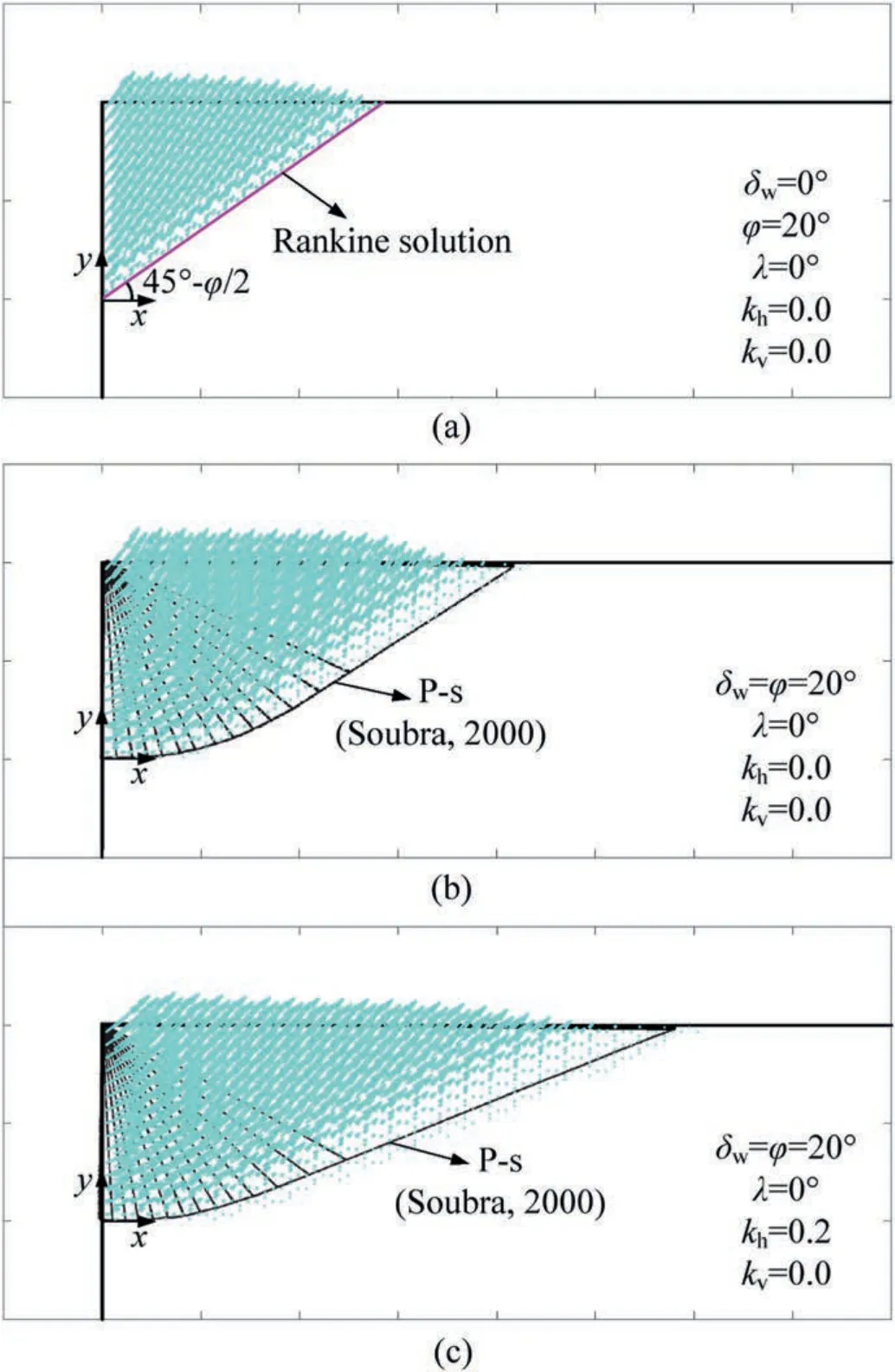
Fig.3.Velocity fields of this study compared with the failure planes of: (a) static Rankine solution,(b)static solution in Soubra(2000)and(c)seismic solution in Soubra(2000).
Another comparison is made with considerations to MPd analysis,with comparing results portrayed in Fig.4.Similar as above,P-s FEUB solutions ofKPare again verified by Soubra(2000)with the kinematic method.Note that a smaller upper-bound solution is predicted from this study,which demonstrates a better estimate ofKP,particularly at higher δwvalues.If the original pseudo-dynamic approach is adopted for comparison,P-d FEUB and FELB solutions are increased slightly,in contrast to the P-s results.However,it shows that a significant decrement inKPis resulted from the use of modified pseudo-dynamic approach.The decreased MP-d solutions ofKPis attributed to amplified seismic forces which facilitate soils to reach its passive limit state.With the use of same parameters and MP-d approach,theKPsolutions from limit equilibrium(Rajesh and Choudhury,2017)are closer to FEUB results,especially at larger δw.On one hand,it indicates the robustness of the MP-d FEUB procedure for predicting seismic passive earth pressures.On the other hand,it reflects that limit equilibrium solutions are neither lower-or upper-bounds.Manifestly,an exponent increase in passive earth pressure coefficient is observed with increasing wall friction angles.This is because the presence of wall friction is to prevent backfilling soils moving upwards to reach its passive limit state,thereby requiring larger lateral forces to push soils at limit state.Interestingly,discrepancies between FEUB and FELB solutions gradually increase with increase of the angle δw,which demonstrates that such angle is quite sensitive and the selection of a proper δwhas a significant effect onKP.
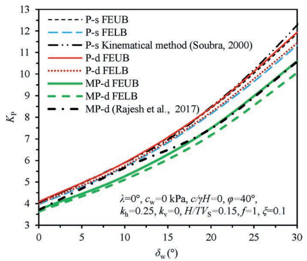
Fig.4.Comparison of P-s,P-d and MP-d solutions of KP from different approaches.
4.2.Discussion on different earthquake inputs
In the following study,three types of earthquake inputs(seismic acceleration) are discussed,including P-s,P-d and MP-d.The solutions are obtained under the effects of wall parameters(H,λ,cw,δw),soil properties(γ,c0,ch,φ0,φh)and earthquake parameters(kh,kv,T,VP,VS,f,ξ),with the default input parameters:H=5 m,λ=10°,cw=10 kPa,δw=20°,γ=18 kN/m3,c0=25 kPa,ch=15 kPa,φ0=30°,φh=25°,kh=0.15,kV=0.5kh,H/TVS=0.25,VP=1.87VS,f=1,ξ=0.15.
Its separate effects on passive earth pressure coefficient are investigated and compared as presented in Fig.5,where the dynamic properties of earthquake and linearly varied MC strength parameters are considered.Hereof,H/TVSratios vary from 0.03 to 0.6,which could cover a quite large range of seismic examples(e.g.frequency of 0.6-12 Hz,for the case ofH=5 m andVS=100 m/s).For ease of distinction,positive acceleration is defined as rightwards and upwards.Undoubtedly,KPin the P-s results remain unchanged underH/TVS,due to the use of constant seismic coefficients.In contrast,P-d solutions ofKPshow an upward trend with the increase ofH/TVS,for the case ofkv=0.5kh,which are no less than P-s results.This demonstrates that the optimal case appears when the vertical seismic forces act downwards and the downward force inhibits backfilling soils to reach its passive limit state,thereby requiring larger lateral thrust.However,for the case ofkv=-0.5kh,an opposite outcome is produced,i.e.theKPvalues in the P-d gradually decrease with increasingH/TVSand are ought to be less than P-sKPin this aspect.It is stemmed from the timing to reach an optimal passive limit state,which is influenced by the combined effects ofH/TVSand direction of vertical seismic forces.Given a duration of P-d earthquake,an increasingH/TVSratio tends to invert the direction of vertical seismic forces in the optimization ofKP,in contrast to P-s cases.However,owing to the introduction of MP-d approach where complicated expressions are derived to represent seismic accelerations,KPresults are nonlinearly affected by its dynamic properties.Specifically,MP-dKPexperiences a significant decrement,followed by an upward trend,and then decreases and increases repeatedly,whenH/TVSincreases.This is mainly attributed to the cyclic properties of MP-d seismic accelerations.More importantly,the minimalKPvalues are sought at certain scenarios,which could push backfills soils to reach its passive limit state.Such minimal values are resulted from the‘resonance’ effects when earthquake frequencies equal the natural frequencies of soils,particularly the fundamental soil frequency atH/TVS=0.25.Meanwhile,these results are highly associated with soil damping which aids to attenuate acceleration amplification.The case ofH/TVS=0.25 demonstrates a worst case in passive earth pressure analyses and is hence adopted in the following calculations.Interestingly,it is found that the minimalKPappears at differentH/TVSfor the cases ofkv=±0.5kh.The main difference herein lies in the initial direction of vertical acceleration,which demonstrates an initial phase angle difference.Accordingly,phase angle plays an important roil in the magnitude ofKPand timing to reach its limit state.Overall,a passive state is easily to be achieved when the vertical seismic forces act upwards,with less lateral thrust required to push backfills soils,indicating a most dangerous scenario for the occurrence of passive failure.Meanwhile,MP-dKPresults are also calculated from average soil cohesion and friction angle,besides linearly varied profiles.It is observed thatKPshows an exactly same trend as that of using linearly MC parameters,with the increase inH/TVS.Nonetheless,a much lessKPis induced when average MC strength parameters are assumed to represent linearly profiles,which will be further discussed later.

Fig.5.Effects of dynamic properties on seismic KP.
Note that in FEUB modelling,the velocity fields and failure planes can be readily obtained through post-processing.Effects of the P-s,P-d and MP-d seismic accelerations are therefore discussed with the above parameters when MC strength parameters are assumed to linear profiles andkv=0.5kh,as portrayed in Fig.6.At the worst case for MP-d analyses,i.e.H/TVS=0.25,it is found that passive failure blocks induced by the P-s and P-d accelerations are similar in shape and dimension,and in such case the increased PdKPvalue is resultant from downward seismic forces.However,a much larger failure block is produced to reach the passive limit state in the MP-d analysis,because the ‘resonance’ effects maximally amplify seismic accelerations.Meanwhile,another case withH/TVS=0.5 is also discussed and the required failure block becomes much smaller in contrast to the case ofH/TVS=0.25.Although the earthquake frequency is approaching to second-order natural frequency of soils herein,amplification of seismic accelerations is attenuated by soil damping,and hence fewer lateral forces produced from earthquakes are provided and more other lateral forces are required to push backfill soils to reach its limit state.It is likely that the critical failure plane is composed by a curved section near the wall and a straight line far away from the wall.
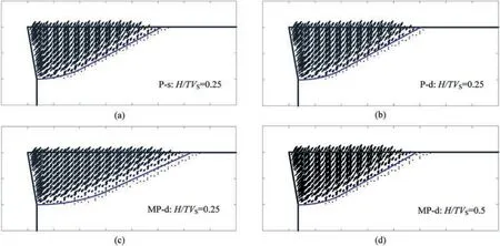
Fig.6.Velocity fields and failure planes from:(a)P-s analysis with H/TVS=0.25,(b)P-d analysis with H/TVS=0.25,(c)MP-d analysis with H/TVS=0.25,and(d)MP-d analysis with H/TVS=0.5.
As discussed above,the P-s,P-d and MP-d approaches are adopted to represent seismic accelerations.It is noted that soil amplification factorfis used to directly portray linearly amplified acceleration profiles when the shear waves propagate upwards.In contrast,seismic accelerations amplify nonlinearly in the MPd approach,and the amplification is restrained by soil damping ξ.Fig.7 presents the effects of these two parameters on seismicKPwherefvaries from 0.6 to 1.4 and ξ changes from 0.1 to 0.2(normalized by 0.15 in this figure),based on the parameters used in Fig.5.As expected,theKPvalue in the P-s solutions is irrespective of factorsfand ξ,which are not included in constant seismic accelerations.It is observed that a linear decrement inKPis induced by an increase off.A largefmeans increased acceleration and seismic forces to push soils rightwards,thereby requiring less lateral thrust and passive earth pressures in turn.In this way,selection of a proper factorfcan produce an equivalentKPas that of P-s approach.As for MP-d analyses,due to the soil damping,the FEUB and FELB solutions ofKPare significantly increased with increasing ξ.The larger ξ,the less seismic forces,and the more lateral forces required to push backfilling soils.Since the worst scenario(atH/TVS=0.25)is discussed herein,the amplified seismic acceleration is still larger than those of P-s and P-d inputs,theKPvalue is hence smaller.Less than 5%difference between FEUB and FELB solutions demonstrates a quite reliable prediction of true passive earth pressure (KP).

Fig.7.Effects of soil amplification factor f and soil damping ξ on seismic KP.
5.FEUB and FELB solutions
Following the preceding FEUB and FELB procedures,the P-s,Pd and MP-d solutions of passive earth pressure coefficients are calculated.In this section,some influence factors such as wall inclination angle(λ),wall friction angle(δw),wall cohesion(cw),and linearly increased MC soil strength parameters are discussed,aiming to provide a better understanding of their effects on a rigid retaining wall at limit state.These results are presented in terms of dimensionless coefficientKP,for the ease of practical use in the design or assessment of retaining wall problems.
Fig.8 illustrates the effects of wall inclination on the P-s,P-d and MP-d solutions ofKP,considering linearly varied and constant(average) MC strength profiles.Manifestly,KPdecreases significantly with the increase of angle λ,demonstrating that passive failure is more likely to happen at large and positive λ values.Note that in site where an arch bridge is to be designed or constructed,it is fortunate to find that the λ value as defined in Fig.1 is usually negative,and hence a much larger lateral force is required to make surrounding soils reach its passive limit state.In other words,such topography tends to have a large capacity to resist the thrust force transferred from the abutment.Similar as above,P-dKPatkv=0.5khis a little bit greater than P-s solutions because the optimal P-d solution is sought when vertical seismic forces act downwards.Reversely,the MP-d FEUB and FELB solutions are much less than the above,owing to amplified seismic forces which facilitate to push soils upwards.For the case of backfilling soils with a linearly varied MC strength profile,the use of average strength parameters tends to apparently under-estimate passive earth pressures,based on which the design of such retaining wall would be not economical.Therefore,in an effort to well predict solutions of seismicKP,adoption of meaningful parameters is a prerequisite,such as reliable soil parameters and MP-d acceleration inputs with more detailed dynamic information.
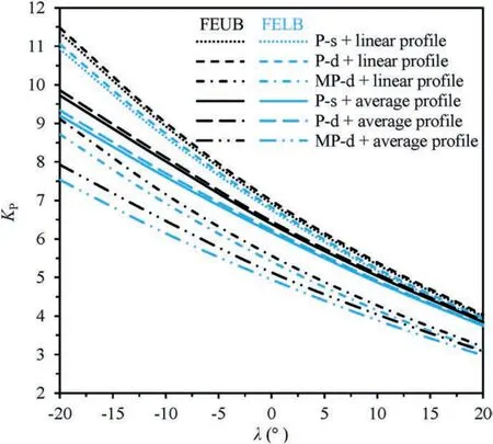
Fig.8.Influence of wall inclination angle on seismic KP.
In Rankine method,a smooth wall is assumed,and wall friction effects cannot be accounted for.Resorting to powerful FEUB and FELB procedures,non-zero wall friction can be readily considered,and its effect on seismic passive earth pressure coefficients is illustrated in Fig.9.It is expected that an increase in wall friction angle tends to produce a largeKPvalue.Since the presence of wall friction is to prevent nearby soils moving upwards,it inhibits soils to reach its passive limit state,and additional lateral force is therefore required.Again,it is substantiated that the P-d solutions are slightly greater than P-s results,and the use of average MC strength parameters could under-estimateKPresults.In contrast,MP-dKPis roughly 20% lower than the pseudo-static in the presence of large wall friction.More importantly,both FEUB and FELB solutions are computed.It is observed that the discrepancies between upper-and lower-bound solutions gradually augment with increase of the wall friction.However,less than 4.2% difference is induced,demonstrating a sound estimate of true passive earth pressure coefficient because it is well within this small range.A more accurateKPis estimated if a rigid retaining wall is not that rough,and this is substantiated by a nearly true solution obtained for a smooth wall in Fig.2.
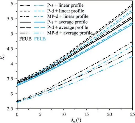
Fig.9.Influence of wall friction angle on seismic KP.
Velocity fields and failure planes under the effects of wall inclination and friction angles are shown in Fig.10 where MC strength parameters are assumed to linear profiles in the MPd analyses.Similar to that in Fig.3a,the critical failure plane is likely to be a straight line for a smooth wall,although such wall is inclined at 10°outwards.Note that with the increase of angle δw,the passive failure block becomes larger,thereby requiring greater lateral force(alsoKP)to push soils behind a retaining wall to reach its passive limit state,as shown in Fig.9.Meanwhile,the failure plane near wall toe gradually becomes curved.If a rigid retaining wall is designed with a negative λ value (e.g.-10°),the area encompassed by velocity fields continues to increase,in contrast to that of λ=10°.The same explanation can be used to interpret the change pattern of seismicKPin Fig.8.Overall,it shows that soils behind a rigid retaining wall show a rotational-translational failure mode,from the perspective of velocity fields.

Fig.10.Velocity fields and failure planes under different λ and δw values: (a) λ=10°,δw=0°,(b) λ=10°,δw=10°,(c) λ=10°,δw=20°,and (d) λ=-10°,δw=20°.
Apart from wall friction,wall cohesion is another parameter influencing seismic passive earth pressure on a retaining wall,and its effect is presented in Fig.11.Similar to wall friction’s effect,an increasingKPis produced with an increment of wall cohesion,and differently,its increasing trend tends to be linear,which is attributed to a linear contribution of wall cohesion’s effect to total external rates of work and can be found in Eq.(10).As expected,the largestKPis yielded with the use of P-d approach,followed by P-s one,and a much lessKPis obtained by MP-d approach.This depends on the magnitude of seismic forces,which facilitates the backfilling soils to reach a passive limit state.The lager seismic forces to push soils from the MP-d analysis,the smaller thrust force from the retaining wall required.Based on different outcomes produced by those three seismic inputs,it is preferred to adopting the seismic acceleration closer to that in practice,so as to yield more reliable results.Again,it displays that the use of average MC parameters would under-estimate seismic passive earth pressure coefficient,in comparison with a linearly increased profile for soil cohesion and friction angle.
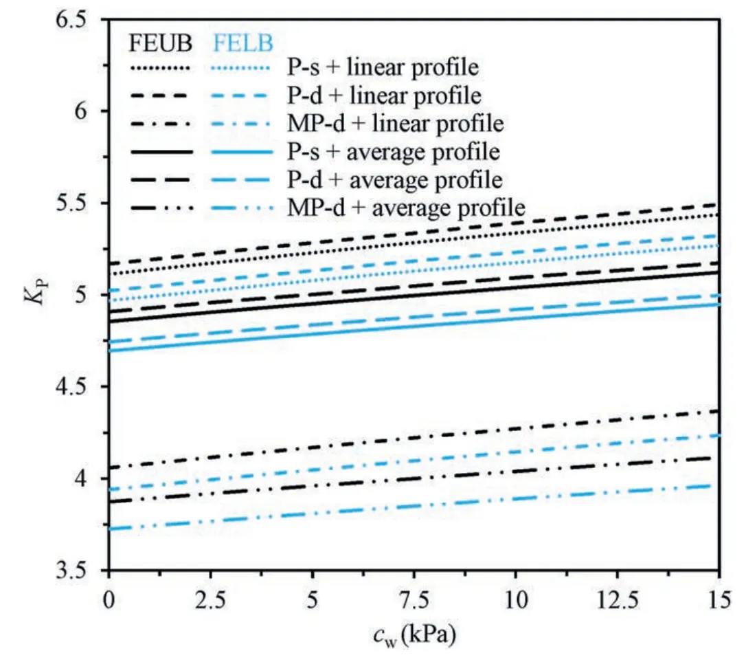
Fig.11.Influence of wall cohesion on seismic KP.
It is not unusual that soil cohesion tends to present a linearly increased profile along depth in backfilling soils with varied degrees of compaction.Adoption of FEUB and FELB method could readily take these effects into consideration,and the results are shown in Fig.12.Hereof,soil cohesion at ground surface is fixed asch=15 kPa,and varyingc0values are in the range of 15-30 kPa.Apart from a linear increase in soil cohesion,an average profile specific to arithmetic mean ofchandc0is considered as a special case which is widely adopted in conventional limit analysis.Manifestly,KPtends to increase linearly with the increase of soil cohesion increment,regardless of differing earthquake inputs and FEUB or FELB methods.Overall,the use of average profile produces smallerKPvalues,in contrast to the linear profile,and the discrepancy becomes gradually widened.It also shows that adoption of MP-d approach yields a much lowerKP,when comparing with P-s and P-d solutions.The reducedKPis highly dependent onH/TVSratios which play an important role in the amplification of seismic forces.As stated earlier atH/TVS=0.25,resonance effects occur,and seismic forces are amplified to the highest level,providing the maximum driving force to push backfilling soils to reach its passive limit state,thereby requiring least lateral forces with smallestKPin turn.Aiming to design a conservative and economical retaining wall,it is of vital engineering significance to have a reliable soil strength profile and a proper manner to consider external loadings such as seismic forces.
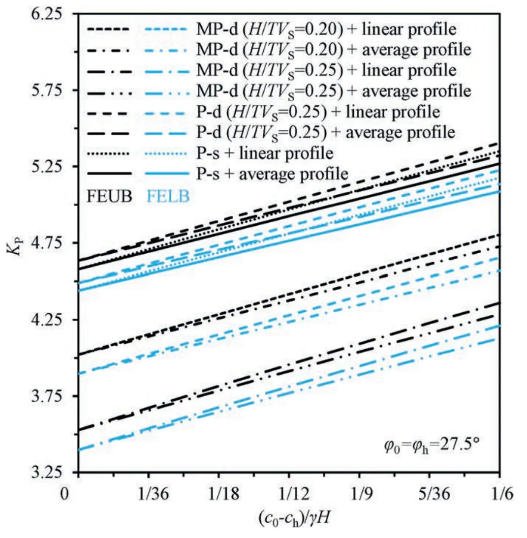
Fig.12.Influence of soil cohesion increase on P-s,P-d and MP-d solutions of KP.
Apart from varied soil cohesion,internal friction angle of soils may also vary with depth,due to geological formation process.At fixed soil friction angle at ground surface (e.g.φh=25°),Fig.13 presents the effects of soil friction angle at the bottom (φ0) on passive earth pressure coefficients.As expected the FEUB and FELB solutions ofKPexperience an upward trend when φ0is increased from 20°to 30°.An increasedKPvalue is attributed to additional resistance provided by soils behind a wall to resist its upward movement,which in turn requires more lateral force to push soils to reach passive limit state.For example,KPat φ0=30°is 34.5%-41.2% (depending on the adoption of different seismic inputs)higher than that at φ0=20°.This demonstrates that soil friction angle has a substantial effect on the determination ofKP.If an average soil friction angle φ is assumed to represent such linear profile,it is observed that at φ0(φ)=25°the same solution is obtained.However,KPon the left side of this point is greater for the case of using constant profiles,and vice versa.In other words,the use of assumed constant soil friction angle without considering its true profile may over-estimate or under-estimateKPsolutions.In contrast to the P-s and P-d solutions withf=1.0,the MP-d solutions are much lower and highly dependent uponH/TVSratios.As for above results,the discrepancy between FEUB and FELB solutions is as low as 4.2%,based on which trueKPvalue is well estimated.
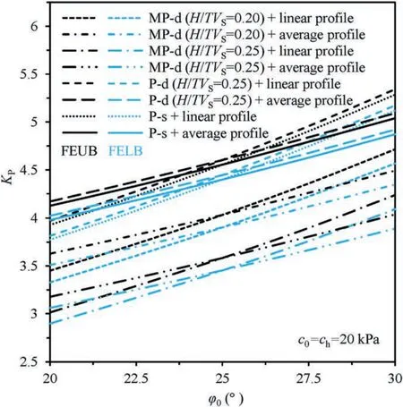
Fig.13.Influence of soil friction angle φ0 on P-s,P-d and MP-d solutions of KP.
6.Conclusions
This study aims to predict seismic passive earth pressure (coefficient)acting on a rigid retaining wall based on plasticity theory.Pseudo-static,original and modified pseudo-dynamic approaches are adopted to represent seismic acceleration inputs.In order to account for linearly varied MC soil strength profiles in the process of generating a kinematically admissible velocity field and a statically allowable stress field,the finite element method is adopted to discretize the domain of interest into finite elements.
(1) Based on discretized feasible velocity and stress fields,stress equilibrium and work rate equations are constructed,and specific upper-and lower-bound solutions are obtained with an interior point algorithm,forming the FEUB and FELB procedures.Combining the merits of limit analysis with finite element method,the proposed FEUB and FELB procedures are powerful to consider complicated scenarios which cannot be readily solved in conventional upper-and lower-bound analyses.After having validated the robustness of the proposed FEUB and FELB procedures with published literature,the effects of influence factors such as wall inclination and friction angle,earthquake inputs and MC strength properties onKPare investigated.
(2) At passive limit state,the required lateral force is increased with increments in wall friction angle,soil damping ratio and MC strength parameters,and with a decrement of wall inclination angle and soil amplification factor,thereby producing an increasedKP.It shows that a more reliable prediction of seismic passive earth pressure coefficient can be obtained by virtue of modified pseudo-dynamic approach where more dynamic properties of an earthquake are accounted for and with the use of a closer to actual MC soil strength profiles.
(3) Owing to amplified seismic acceleration,the FEUB and FELB solutions ofKPare significantly reduced,which tends to indicate a more dangerous scenario.The use of constant MC strength parameters to represent linearly varied profiles would over-estimate or under-estimate seismicKP.Another finding of this study is that less than 5% difference between the FEUB and FELB solutions of seismicKPis obtained,and such narrowed range of upper and lower bounds aids to provide a reliable and meaningful estimate for true passive earth pressures.
Data availability statement
The data from the present study are available by the corresponding author after reasonable request.
Declaration of competing interest
The authors declare that they have no known competing financial interests or personal relationships that could have appeared to influence the work reported in this paper.
Acknowledgements
The research was financially supported by National Natural Science Foundation of China(Grant Nos.52108302 and 52009046),Fundamental Research Funds for the Central Universities of Huaqiao University (Grant No.ZQN-914).
 Journal of Rock Mechanics and Geotechnical Engineering2024年3期
- Journal of Rock Mechanics and Geotechnical Engineering的其它文章
- Limit load and failure mechanisms of a vertical Hoek-Brown rock slope
- Bearing capacity of circular footings on multi-layered sand-waste tire shreds reinforced with geogrids
- Experimental investigation on the permeability of gap-graded soil due to horizontal suffusion considering boundary effect
- Damage constitutive model of lunar soil simulant geopolymer under impact loading
- Wetting-drying effect on the strength and microstructure of cementphosphogypsum stabilized soils
- A novel relationship between elastic modulus and void ratio associated with principal stress for coral calcareous sand
