Multi-UAVs Collaborative Path Planning in the Cramped Environment
Siyuan Feng , Linzhi Zeng , Jining Liu , Yi Yang , and Wenjie Song ,,
Abstract—Due to its flexibility and complementarity, the multi-UAVs system is well adapted to complex and cramped workspaces, with great application potential in the search and rescue(SAR) and indoor goods delivery fields.However, safe and effective path planning of multiple unmanned aerial vehicles (UAVs)in the cramped environment is always challenging: conflicts with each other are frequent because of high-density flight paths, collision probability increases because of space constraints, and the search space increases significantly, including time scale, 3D scale and model scale.Thus, this paper proposes a hierarchical collaborative planning framework with a conflict avoidance module at the high level and a path generation module at the low level.The enhanced conflict-base search (ECBS) in our framework is improved to handle the conflicts in the global path planning and avoid the occurrence of local deadlock.And both the collision and kinematic models of UAVs are considered to improve path smoothness and flight safety.Moreover, we specifically designed and published the cramped environment test set containing various unique obstacles to evaluating our framework performance thoroughly.Experiments are carried out relying on Rviz, with multiple flight missions: random, opposite, and staggered, which showed that the proposed method can generate smooth cooperative paths without conflict for at least 60 UAVs in a few minutes.The benchmark and source code are released in https://github.com/inin-xingtian/multi-UAVs-path-planner.
I.INTRODUCTION
IN recent years, multiple unmanned aerial vehicles (UAVs)have been widely used for search and rescue (SAR), with the development of cooperative localization and mapping,object detection, path planning, formation control and other technologies [1]-[4].Among them, planning a set of feasible and conflict-free flight paths is critical for mission execution in complex environments, especially in cramped workspaces like densely packed buildings.Although there has been a considerable amount of related researches about messy indoor environments [5], wild environments [4], and emergency scenarios [6], it is still very difficult for the UAVs system to plan multiple trajectories simultaneously in a cramped environment with higher obstacle density and more diverse obstacle types.The system is challenged from two aspects: 1) Path generation: The safe flight area (like window, door, etc) is always tight, making it difficult to generate multiple safe and smooth trajectories simultaneously.2) Conflict avoidance:cramped space constraints the detour room when UAVs meet each other, resulting in frequent conflicts and collisions both in time and space.
In this paper, we propose a hierarchical framework to solve the cooperative path planning problem of multi-UAVs in the cramped environment.On the one hand, we choose the path search algorithm based on kinematic extension and add search acceleration strategies to make the path generation faster while ensuring its feasibility.On the other hand, we improve the enhanced conflict-base search (ECBS) algorithm in the centralized multi-UAVs planning method, which can handle the conflicts in the global path planning and avoid the occurrence of local deadlock.Compared with existing methods, our method solves these two challenges at the same time, and the contributions are summarized as follows:
1) A hierarchical planning framework based on the ECBS algorithm is proposed for multi-UAVs cooperative path planning problem in cramped environments, which has solved the problems of size-constrained obstacle avoidance and spatiotemporal conflict avoidance.
2) Relying on the path search algorithm based on the kinematic model of UAVs, the smoothness of output paths is improved, which is convenient for the tracking control of UAVs.
3) We have conducted detailed experiments in the specially designed cramped environment test set, and the source code and test set are published, available for comparison by relevant researchers.
II.RELATED WORK
According to the system architecture, researches focusing on multiple UAVs cooperative path planning can be broadly divided into two types: decentralized architecture and centralized architecture [7].
A. Decentralized Architecture-Based Methods
For decentralized architecture-based planning, each UAV actively obtains the information of other UAVs to generate its own optimal path to its destination, and conflict resolution is conducted real-timely when future collisions are detected.Therefore, decentralized planning methods have high computational efficiency and good scalability, which recently received much attention.Most of the current decentralized planning methods are based on the real-time reflection to avoid conflicts and collisions.For example, velocity obstacle(VO) [8], [9] is developed as a lightweight approach to generate collision-free control commands.It defines a collision cone for the ego robot in the velocity domain (the cone is determined by the model size and relative velocity of other robots), and every velocity that does not fall within the area is a safe choice.Reciprocal velocity obstacle (RVO) and optimal reciprocal collision avoidance (ORCA) [8], [10] are proposed to solve the oscillation problem of VO.Besides, distributed model predictive control (DMPC) [11] is widely used for aerial swarm robotics, which improves the path quality significantly.However, these reactive planning methods can not guarantee no deadlock [12] and are poorly suited to problems in cramped environments.
B. Centralized Architecture-Based Method
Centralized planning is carried out uniformly through a central system with information on the states of all UAVs at each time step.It usually requires finding the overall optimal conflict-free path for multiple agents system in the defined graph,also known as multi-agent path finding (MAPF) [12].The commonly used solution methods can be divided into optimization-based approaches, grid-based approaches, and their combinations [13].The optimization-based approaches usually formulate the path generation problems as a mixed-integer quadratic programming (MIQP) or sequential convex programming (SCP) problems [14], [15] that append collision constraints at each discrete time step.These methods use advanced algorithms such as ant colony optimization (ACO)[16] to jointly optimize the trajectories of all robots, which can ensure the optimality of the overall system.However, they are intracTable for large teams and complex environments because an additional adaptation process is required to find proper discretization time step depending on the size of robots and obstacles.In contrast, grid-based approaches like conflict based search (CBS), enhanced CBS (ECBS), improved CBS(ICBS) and CBS with heuristic (CBSH) [17]-[19] can solve them more efficiently and can prevent deadlock.In addition,there are also many researches combining these two approaches using a two-stage pipeline [13], [20], [21].First,they plan an initial trajectory through a grid-based planner.Then they construct a safe flight corridor (SFC) [21], which indicates the safe region of each agent.Finally, they smooth the trajectories with the optimization-based approach so that UAVs can follow smoothly.Representative researches such as[13], [21] demonstrated these methods’ effectiveness in both simulated and real environments.However, these methods are applicable to discrete spaces.Our work employs an improved ECBS algorithm as a planning method to deal with obstacles that are easy to cause deadlock in continuous spaces, such as one-way channels.
In addition, many researches also have improved the centralized method in two aspects: 1) improve computational efficiency and 2) make the model more realistic.For the first problem, a decoupled scheme like sequential planning [14],[22] is widely used.It divides the planning problem into multiple batches and solves them sequentially, improving computational efficiency significantly with little sacrifice on completeness.The strategy is also applied to our work.For the second problem, previous MAPF algorithms assume that an agent occupies only a single location at any given time, e.g., a single cell in a grid.This limits their applicability in many real-world domains with geometric agents in lieu of particle model.To solve it, Liet al.[23] formalized a “large agent”which occupies multiple points simultaneously.Based on this work, our work uses the body conflict description [24] to reflect the characteristics of the UAV model, such as volume and downwash effect.Further, we take the UAV kinematic model into consideration during path generation so that the UAVs can directly execute the output paths.
III.PROBLEM STATEMENT
Multi-UAVs cooperative path planning in cramped environments is a challenging problem.On the one hand, the narrow physical space limits the room for UAVs to detour each other when they meet, which increases the probability of conflict.On the other hand, rotorcraft generates a large, fast-moving volume of air underneath their rotors called downwash, which will also interfere the route tracking of other UAVs in the vicinity, resulting in chain collisions or large-scale disturbances, especially when the number of UAVs is large.
Compared with the classical MAPF methods that merely consider the 2D planar model and simple moving behavior,more details about the realistic model should be considered in these scenarios.We first describe the UAV model used in our work and then define the multi-agent pathfinding problem.
A. Internal Impact Model
In a MAPF problem, the setting of the collision model is critical.The downwash effect caused by the rotation of wings will seriously affect the flight stability onZ-axis.Therefore,apart from the physical size, we also incorporate the downwash effect into the collision model and unify it as an ellipsoid, which is shown in Fig.1, where 0 <rx=ry<rz.Usually,therzis set to be ten times the radius of the UAV in practice.Differentially flat [25] indicates that the full-dimensional planningproblemin UAV’sstatespaceχ[canbetr]anslated intoalower-dimensionaloutputspaceδx,y,z,ψ, wherex,y,zrepresent the position in the space andψrepresents its yaw angle.Furthermore, when the yaw angle is not relevant to the mission, it is used to set as a fixed value to save computing costs.Finally, we can focus our planning on three-dimensional Euclidean space, which is convenient for calculation.
B. Problem Definition
DefineW⊂R3as a workspace,Ows,Fws∈Was obstacle

For the evaluation criteria of the solution, unlike single UAV planning, multi-UAVs cooperative path planning is often measured by makespan and sum of costs [26].The former represents the maximum completion time, and the latter represents the total cost of all paths.
IV.METHOD
Our method is based on Car-like CBS [24] first proposed for multi-cars path finding, which can seach a set of safe and kinodynamic feasible paths that are minimal with respect to time duration and control cost in a continuous workspace.As shown in Figs.1 and 2, the process is similar to the standard ECBS algorithm [27] with the following adjustments.For the high-level search, we apply a body conflict description for conflict detection, which is well suited for a variety of new conflict types casused by 3D environment.For the low-level search, we use motion primitives rather than straight line as graph edge, which respecting the quadrotor dynamic.
Deadlock and collision avoidance can be guaranteed by conflict detection and node feasibility detection.When a deadlock or conflict is detected, a temporal constraint will be set for one of the UAVs to prohibit it from entering a region at a certain time to ensure that temporal conflicts can be excluded in advance.And the path search algorithm based on occupancy map will discard the infeasible nodes that collide with obstacles to ensure the path safety.

Fig.2.The planning system accepts UAV model parameters and flight goal points, and obtains multiple UAV trajectories without internal conflicts through path search layer and conflict coordination layer.
A. High-Level Constraint Tree
Like the ECBS algorithm, the high-level part is based on a constraint tree (CT), and each leaf nodencontains a set of constraints (n.constraints), a solution (n.solution), and the total cost (n.cost).A focal search is used to compute the bounded suboptimal solutions: it maintains an OPEN list and a FOCAL list in an A* search framework.The FOCAL list contains elements that are in the OPEN list and within a suboptimal lower bound LB.Letfmin(i) be the minimalfvalue of an agentaiin its low-level OPEN list, and the LB can be defined asThe nodes in focal are selected as follow:
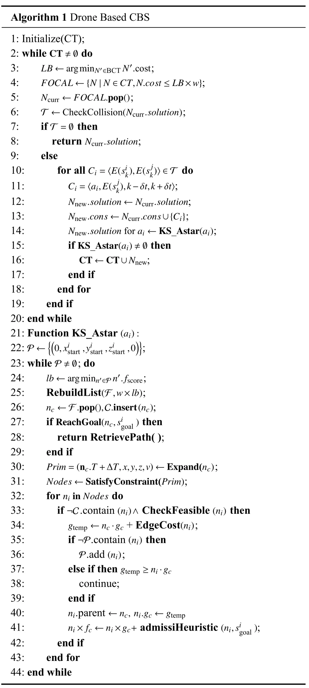
wherewis a user-provided parameter usually greater than 1.The expansion of the CT works is shown in Fig.3(a).Take two UAVs agent1 and agent2 for example: firstly a node containing the two agents is popped from the focal list based on a secondary heuristic, usually calculated by the number of total conflicts.Then, the conflict detection module checks the two paths against the internal impact model.If two agents arrive at the same area simultaneously, a conflict 〈E(ak1),E(ak2)〉 is recorded, shown in Fig.3(b).To solve the conflict, we produce two relative constraints for both sides:〈a1,E(ak2),[k-Δt,k+Δt]〉 fora1and 〈a2,E(ak1),[k-Δt,k+Δt]〉 fora2, which means agent1 can not pass through the elliptical regionE(ak2)within the time period 〈[k-Δt,k+Δt]〉, and the same for the latter.Constraints are inserted at the corresponding positions in the constraint set, and thus two new child nodes are created to join the OPEN list.We repeat this process until finding a node without conflicts.The pseudocode of this process is Lines 1-20 in Algorithm 1.
Algorithm 1 Drone Based CBS 1: Initialize(CT);CT ≠∅2: while do LB ←argminN′∈BCT N′.cost 3: ;4: ;Ncurr ←FOCAL.pop()FOCAL ←{N|N ∈CT,N.cost ≤LB×w}5: ;T ←CheckCollision(Ncurr.solution)6: ;T =∅7: if then Ncurr.solution 8: return ;9: else Ci=〈E(sik),E(sjk)〉∈T 10: for all do Ci=〈ai,E(sj k),k-δt,k+δt〉11: ;Nnew.solution ←Ncurr.solution 12: ;Nnew.cons ←Ncurr.cons∪{Ci}13: ;Nnew.solution for ai ←KS_Astar(ai)14: ;KS_Astar(ai)≠∅15: if then CT ←CT∪Nnew 16: ;17: end if 18: end for 19: end if 20: end while(ai):21: Function KS_Astar P ←{(0,xistart,yistart,zistart,0)}22: ;23: while ; do lb ←argminn′∈P n′.fscore 24: ;P ≠∅25: RebuildList ;nc ←F.pop(),C.insert(nc)(F,w×lb)26: ;ReachGoal(nc,si goal)27: if then 28: return RetrievePath( );29: end if Prim=(nc.T+ΔT,x,y,z,v)←Expand(nc)30: ;Nodes ←SatisfyConstraint(Prim)31: ;ni in Nodes 32: for do¬C (ni)∧ (ni)33: if.contain CheckFeasible then gtemp ←nc·gc (ni)34: + EdgeCost ;¬P (ni)35: if.contain then P (ni)36:.add ;gtemp ≥ni·gc 37: else if then 38: continue;39: end if ni ←nc, ni.gc ←gtemp 40:.parent ni×fc ←ni×gc+ (ni,si goal)41: admissiHeuristic ;42: end if 43: end for 44: end while
B. Low-Level Path Searching
In the path generation part, we combine well-known path search algorithms [24], [28] to make our work get the following characteristics:
1) It can plan paths satisfying the kinematic and dynamic constraint.
2) It can impose spatio-temporal constraints containing volumetric information.
3) It can search feasible state sequences faster than ordinary A* optimal search.
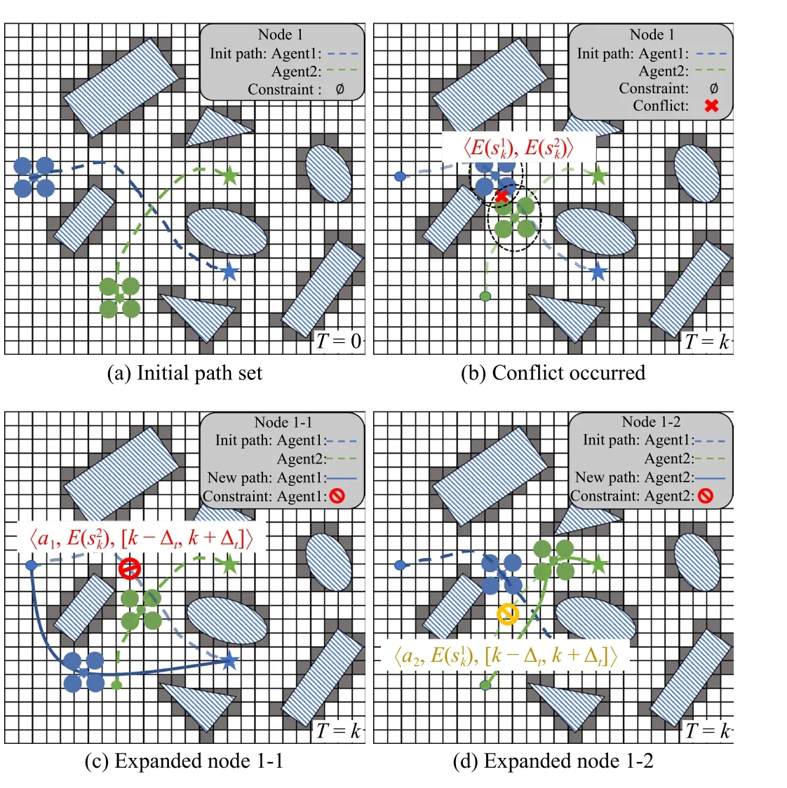
Fig.3.Schematic diagram of conflict coordination module.In (a), each UAV has an initial path that does not consider coordination.And a conflict at time k is detected in (b).Then, two child nodes with respective constraint are expanded from the conflict, as shown in (c) and (d).Finally, a node with space-time constraint is selected and passed into the path search module to get a new path.
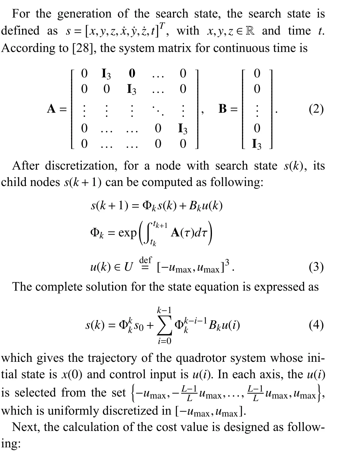
where the actual costgcrepresents the cost of arrival time and control smoothness, and the heuristic costhcrepresents the desire to reach the goal.Ingc, the control smoothness is determined by the momentum change and the angle change caused by the input.And inhc, the desire is calculated by the distance between the current point and the goal point, wheredcis Euclidean distance andD(sc) is the path length calculated by the A* algorithm.It is worth noting that the kinetic energy and time penalty functions ingcare convex for their quadratic and linear functional forms [29], and since the angle change is always between [-90°,90°],F(θi) is also convex at this interval.Similarly, the distance calculation functionhcin threedimensional space can also be proved to be convex in form.So the total cost function is a convex function that can be easily calculated.
For each newly expanded node, we check whether it satisfies the spatiotemporal and reachability constraints, and order eligible nodes by cost in the focus list.The full procedure can be shown in Fig.4 and found in Algorithm 1, Lines 21-44.

Fig.4.The UAV performs forward expansion in the form of discrete input,and the unexecutable points are discarded (dotted line).Finally, the optimal execuTable point is selected for the next expansion.
C. Computational Acceleration
The optimal solution of the multi-UAVs path is an NP-hard problem [30].Its computational complexity increases exponentially with the increasing number of agents, which seriously restricts the system’s scalability.To solve this problem,we draw on the idea of priority grouping [13] which divides the UAVs into 「M/k■ (rounded up) groups with different priorities inkunits.Then we make a solution of the previous group as the pre-constraint of the following group, and solve it sequentially according to the group number.It can always limit the complexity of the problem to a reasonable range so that the solution can be completed quickly.Although this approach inevitably results in a loss of optimality, specific experiments are carried out in our work to show its worthiness.
In addition, to speed up planning, we have also added oneshot strategies to the path generation module.When the UAV reaches a certain distance to the goal point, we can directly compute a polynomial curve from current point to the end.If the curve passes the safety and dynamic feasibility checks, the search can be terminated early.The solution of the polynomial can be regarded as a quadratic linear minimum problem with known boundary values.In detail, our work uses Pontryagin’s maximum principle to calculate and obtain the solution as follows:
wherepc,v,pg,vgare the current and goal position and velocity.
V.EXPERIMENT
The planning module is often associated with the perception module and the control module in a complete navigation system, resulting in the final output always affected by the performance or error of other modules.In order to eliminate the influence of other modules on the final result and obtain the real effect of the planning algorithm, it is necessary to use the control variable method.So, we idealize other modules to eliminate the corresponding influence (the map obtained by the planning is a priori and accurate, and the controller is the ideal tracker).Rviz is selected as the software platform for displaying simulation results, and by defining robot motion models as well as environmental barriers, planning results can be accurately obtained.The hardware platform is a PC equipped with an Intel Core i9-3070@5.10 GHz CPU and 32G of RAM.And the boost library is used for mathematical calculations.Besides, we increase the complexity of obstacles in the static environment to focus on testing the global planning and conflict resolution capabilities of the method.
A. Platform Display
A series of highly challenging maps are designed with narrow flight spaces and unique obstacle structures.Unlike the traditional 2D environment or the obstacle map based on columnar obstacles, this experiment adds various types of obstacle objects, such as walls, tunnels, etc.Its structural particularity brings challenges to the coordination and conflict resolution of multiple UAVs.As shown in Fig.5(a), the wall(i) has a vast occlusion area (about 60 m2), which makes UAVs tend to pass through holes in it.However, small holes are easy to cause flying conflicts between UAVs, which is the key problem in a collaborative planning system.Similarly, the tunnel (ii) also forces the agent to fly through the obstacle area by the narrow passage, because the length of the tunnel (10 m)exceeds the path length of the single-time planning of the general decentralized method, and the planning method is required to complete the conflict perception and processing at an earlier time.In addition, the presence of various column barriers (iii) further compresses the safe flight space, making it more difficult for UAVs to avoid each other.
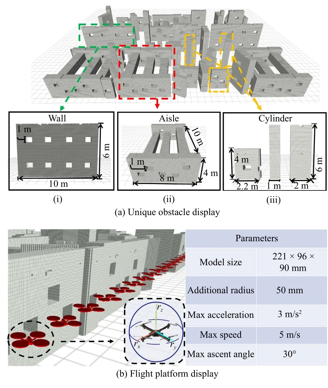
Fig.5.Scene diagram with (a) multiple types of obstacles and (b) the UAV model for planning in simulation environment.
We also build a multi-UAVs flight platform as shown in Fig.5(b).The UAV internal parameters refer to the djiM2 setting, in which the diagonal expansion radius is 0.2 m, the maximum le vel flightspeedis5 m/s,themaximumacceleration is 3 m/s2and themaximumascent angle is 30°.
B. System Test
To thoroughly test the proposed method, 9 representative maps are chosen as experimental environments, which is shown in Fig.6(a).Among them, the first row of maps contains different numbers of obstacle types, the second row only has different arrangements of obstacles, and the third row has different obstacle areas.
Firstly, different flight missions are set up on the carefully selected maps to obtain overall experimental results, as shown in Fig.7 and Table I.As a critical indicator, the total-plantime can simultaneously characterize the experiment’s difficulty and the algorithm’s performance.For the first aspect,experiments (d), (e), and (f) in Fig.7 prove that in a similar environment, when the number of UAVs increases and the setting of flight mission is more likely to lead to conflicts, the planning becomes more difficult, and the experiment has a high task-complexity.And experiments (a), (b), (d), and (e) in Fig.7 prove that in the area to be traversed by the UAV, when the coverage area of obstacles increases and the topology types of obstacles increase, planning is more difficult, and the experiment has high environmental complexity.The overall difficulty of the experiment is determined by the above two,and the summary is shown in Fig.6(b).More importantly, for the second aspect, the proposed method can plan an execuTable path for each UAV in less than half a minute under different environmental and task complexity, which powerfully demonstrates the method’s feasibility.

Fig.6.Experimental scenes display.
Secondly, a short-distance obstacle-crossing experiment is carried out for different obstacles, as shown in Fig.8.On the left side of subgraph Fig.8(a), both agent1 and agent2 tend to fly through the nearest hole to get to their goal points directly.This is in line with the expectations of minimum energy loss and time duration.But, when both are flying at the same time,the small space forces the system to coordinate the flight paths to avoid collision when they meet, leaving one flying in a new channel as shown in the right image.And in the waiting experiment of Fig.8(b), agent1 needs to fly through the corridor, it slows down and waits for agent2 to leave to avoid encountering it in the corridor, thus avoiding the occurrence of deadlock in advance.
C. Comparative Experiments

Fig.7.The maps have different levels of difficulty due to the different types of obstacles and the size of the obstacle areas.The experiment uses 20 UAVs for cross flight, 30 UAVs for random flight, and 40 UAVs for opposite flight.

TABLE I BASIC EXPERIMENTAL RESULTS
In a space containing a large number of complex obstacles,the latest distributed planning method [31] and centralized planning algorithm [21] are selected for comparison with the proposed method.The flight mission is set as UAVs travel 30 mto exchange their positions, and the results are shown in Fig.9 and Table II.We found that the centralized framework requires offline planning in advance, while the distributed method can realize real-time planning and respond more quickly.However, it can be seen that due to the locality of the distributed planning approach [31], the UAV will conduct circling (see Fig.9(a)) for waiting, and sudden changes (see Fig.9(b)) of flight decisions, and long detours (see Fig.9(c)),which will reduce the flight speed.Furthermore, the longest and average trajectory length of distributed method [31] are 63.85% and 32.38% longer than the necessary flight length,while the proposed method is only 18.43% and 14.56%, proving that unnecessary detours and waiting are effectively reduced.Therefore, the centralized approaches have advantages in terms of overall efficiency.Then, we also conducted a comparative experiment with the latest centralized planning approach [21].On the one hand, the path obtained by the initial search in [21] is much rougher than our proposed method,which can not meet the execution requirements; on the other hand, the optimization step in [21] can not obtain results under the constraints of unique obstacles, and the result without constraints (see Fig.9(d)) can not satisfy the collision-free requirement.
D. Ablation Experiments
1)Comparison About Coordination Module
In order to show the effect of the coordination module more clearly, an ablation version is selected to re-run experiments(d), (e), and (f) in Fig.7, the results are shown in Fig.10 and Table III.
The Fig.10 retains the situation when the collision occurred for the first time.It can be seen that in small areas such as the entrance of tunnels and the corner between columns, the UAVs are likely to collide and the total completion rate is less than 30%.The data in Table III also shows that even in the absence of obstacles, UAVs have multiple conflicts during the flight, which shows the necessity and efficiency of the coordination module.

Fig.8.Conflict handling scenarios.
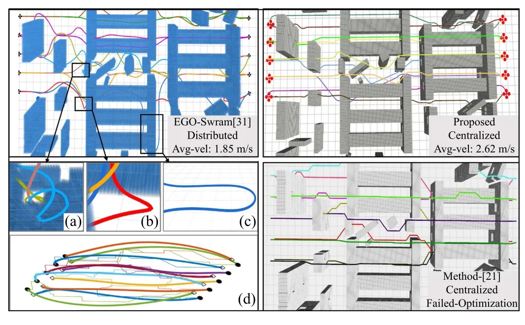
Fig.9.Comparison with other methods.Display of method [21] is the intermediate result.(a) Circling for waiting; (b) Sudden changes of flight decisions; (c) Long detours; (d) Unconstrained result of method [21].
2)Comparison About Kinematic Model
The pure A* algorithm are compared with the proposed planning algorithm in experiments, characterizing the smoothness of the trajectory through the trajectory curvature and velocity-change rate, as shown in Fig.11.
First, based on the experimental results, agent-6 and agent-13 are selected to calculate their speed changes and convert the rate of speed change to the trajectory color for a more intuitive display.Figs.11(a)-11(d) show that: on the one hand,compared with the polyline shape of the pure A* algorithm,the trajectory obtained by the proposed algorithm shows a softer arc shape at the inflection point; on the other hand, the color change of the trajectory obtained by the proposed algorithm is also uniform, indicating that the change of speed isgradual.

TABLE II DIFFERENT METHOD COMPARISON
In addition, the curvature and speed changes of all UAVs are counted to form box plots for quantitative display, as shown in Figs.11(e) and 11(f).The curvature results show that due to the addition of changing-direction penalty, the proposed algorithm maintains the average and maximum values in a lower range, ensuring the smoothness of the path.The speed statistics results show that the addition of kinematic constraints and the kinetic-energy penalty make the proposed algorithm tend to plan a path at a moderate speed, in which the fluctuation is smaller, ensuring the stability of the flight.
3)Comparison About Computational Acceleration
Section IV-C chapter, the accelerated computing methods at both low and high levels are proposed.Comparing the complete version with the version without the accelerated strategy,the effect is measured by planning time and total cost as shown in Fig.12.
For the low level search strategy, different sets of UAVs are used to test the effect.The results are shown in Fig.12(a).It can be seen that, the planning time of the proposed algorithm is generally shorter, and the acceleration effect is more obvious as the scale of the drone increases: The planning efficiency can increase by 32.5% when planning 60 agents.The reason is that when the direct path meets the conditions, the algorithm will not continue to gradually expand the nodes,which effectively saves time.Furthermore, the total cost in the histogram shows that the cost loss caused by the accelerated method is accepTable.
For the high level strategy, priority grouping is used to improve overall planning efficiency.And the total planning time of various numbers of UAVs under different batch sizes(k= 1, 5, 10) is counted as shown in Fig.12(b).It can be seen that the search time of the green line (k= 1) and the red line(k= 5) is generally shorter than that of the blue line (k= 10)with more group members, which demonstrates the advantages of the grouping strategy.
VI.CONCLUSION
This paper proposes a multi-UAVs path planning framework for multi-tasks and multi-agent joint working in cramped environments.The framework consists of a high-level collision coordination module based on an improved ECBS algorithm and a low-level path generation module based on motion primitive sampling.The proposed system plans flight paths for multiple UAVs that meet the kinematic constraints and have no internal collisions in the self-designed cramped map set.The experimental results are shown on the Rviz simulation platform, and the evaluation of planning time and path smoothness proves the feasibility of the framework.

TABLE III COORDINATION MODULES COMPARISON
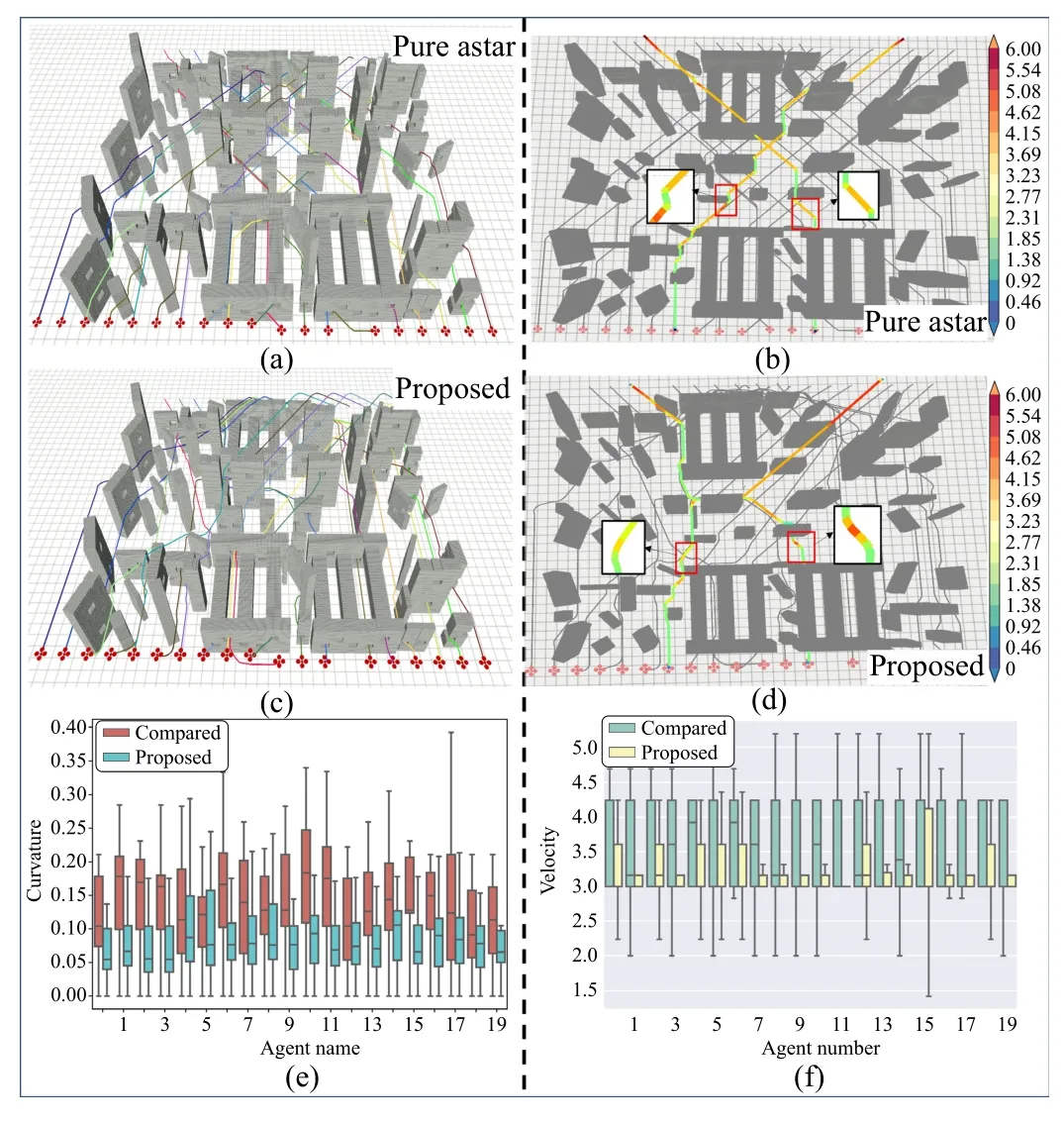
Fig.11.Comparison with pure A* method.(a) Experimental result of pure astar method; (b) Speed-color graph of pure astar method; (c) Experimental result of proposed method; (d) Speed-color graph off proposed method; (e)Comparison of curvature change; (f) Comparison of velocity change.
And as we state in this paper, this work is more concerned with global planning and conflict resolution, where the entire map and perception is deterministic, and for dynamic movement we are more concerned with the movement of other UAVs within the system.However, in some practice situation,when a dynamic obstacle suddenly appears outside the system, a new, undetected conflict will occur, which requires emergency planning to response.This is a new and challenging problem: Localized conflict resolution behavior performed by a single UAV may affect the further flights of other UAVs around it, or even make the entire system chaos.Therefore, a cofilict-free based local planning and emergency response method is needed.In the future, based on this work,we will focus on how to deal with emergency recovery and local conflict resolution for multiple UAVs, so as to further improve the safety of the method in dynamic environments.

Fig.12.Comparison of different computing acceleration methods: (a) Oneshot strategy; (b) Batch-by-batch strategy.
 IEEE/CAA Journal of Automatica Sinica2024年2期
- IEEE/CAA Journal of Automatica Sinica的其它文章
- Reinforcement Learning in Process Industries:Review and Perspective
- Communication Resource-Efficient Vehicle Platooning Control With Various Spacing Policies
- Virtual Power Plants for Grid Resilience: A Concise Overview of Research and Applications
- Equilibrium Strategy of the Pursuit-Evasion Game in Three-Dimensional Space
- Robust Distributed Model Predictive Control for Formation Tracking of Nonholonomic Vehicles
- Stabilization With Prescribed Instant via Lyapunov Method
