Comparative Analysis of Vibration and Noise of Axial Flux Motor with Different Pole and Slot Combinations*
,,*,
(1.School of Electrical Engineering and Automation,Anhui University,Hefei 230601,China;2.National Engineering Laboratory of Energy-Saving Motor &Control Technology,Anhui University,Hefei 230601,China)
Abstract: The electromagnetic vibration noise in axial flux motors was meticulously examined.In this study,24-slot/10-pole and 12-slot/10-pole axial flux motors were chosen as the subjects of research.The spatial characteristics of the axial electromagnetic force were derived analytically and confirmed via two-dimensional Fourier decomposition.The finite-element method was used to simulate the low-order axial modes of both motors.Furthermore,a modal experiment on the stator of a 24-slot/10-pole axial flux motor was conducted to validate the simulation’s accuracy.By integrating the electromagnetic and structural models,a comprehensive multi-physical field model was developed to calculate the vibration noise of the axial flux motor.The precision of this model was subsequently corroborated with noise experiments.The findings from this study aim to offer insights into identifying the sources of vibration noise in axial flux motors.
Keywords: Axial electromagnetic force,vibration,noise,axial flux motors,modal analysis
1 Introduction1
natural frequency of the motor.In Ref.[10],an analytical method was proposed to calculate the radial force,taking into account both the stator grooving and tangential forces.The electromagnetic force acting on the surface of a stator tooth was studied for its temporal and spatial characteristics[11-12].These studies revealed that the lower spatial order of the electromagnetic force significantly impacts motor vibrations and noise.The effect of the polar groove fit on radial flux motors was explored in Refs.[13-14].The findings suggested that as the maximum common factor of the number of grooves decreases,the motor vibration and noise intensify.To delve into the vibration and noise of electric motors,Refs.[15-16]introduced a multiphysics model that integrates electromagnetic,structural,and acoustic radiation components.
Although several studies delved into motor vibrations and noise,there is limited research on axial-flux motors specifically.A numerical prediction model presented in Ref.[17] investigated the vibration and noise in axial flux motors,accounting for the effects of high-order harmonic magnetic fields.It was Owing to their high power density,high efficiency,and compact structure,axial-flux permanent magnet(AFPM) machines have been increasingly used in hybrid vehicles,emergency power generation,and other fields[1-5].In these application scenarios,the vibration and noise of axial flux motors are crucial performance evaluation indicators[6-9].
Furthermore,the vibration and noise of radial flux motors have also been extensively investigated.It is generally accepted that for medium-and low-speed motors,vibration is mainly due to the air-gap electromagnetic force,whereas noise is a parasitic effect of the stator shell vibration.The motor resonates and produces noise when the frequency of electromagnetic force waves is close to or equal to the determined that the vibroacoustic attributes of axial flux motors are predominantly driven by the axial force.In a different approach,Ref.[18] applied the finite element method to ascertain the noise in disc motors.However,a significant limitation of this approach is the time-intensive requirement to establish a solid model.Notably,neither Ref.[17] nor Ref.[18]delved into the origins of vibration and noise,leaving the axial flux motor’s vibration mechanism relatively ambiguous.To address the vibration and noise in external rotor axial flux motors,Ref.[19] introduced a holistic control model that considers the uneven axial force distribution.This model integrates electromagnetic,structural,and acoustic radiation facets.Building on this,Ref.[20] conducted an in-depth examination of the axial electromagnetic force and vibroacoustic features of a single-stator,single-rotor axial flux motor.Their results underscore that the spatial 0thorder axial force has a pronounced effect on vibration and noise,setting axial flux motors apart from their radial flux counterparts.Moreover,Ref.[21] undertook a comparative analysis of the vibration characteristics of flux motors with three distinct winding configurations,shedding light on their respective vibration mechanisms.This analysis yields a potent method to dampen vibrations in dual-stator,single-rotor axial-flux motors.Finally,Ref.[22]studied the impact of rotor position errors,stemming from resolver inaccuracies,on the electromagnetic noise in axial flux motors.It was observed that such positional errors added supplementary sideband frequency harmonics to the current and electromagnetic forces,consequently augmenting the noise harmonics.
Compared to axial flux motors investigated in earlier studies,a more intricate structure is explored in this paper.Specifically,the 24-slot/10-pole motor is characterized by a double-stator single-rotor distributed winding,while the 12-slot/10-pole motor adopts a double-rotor single-stator concentrated winding.In Section 2,the spatiotemporal characteristics of the axial electromagnetic forces under both no-load and loaded scenarios are detailed.The accuracy of these spatiotemporal characteristics is verified using the two-dimensional fast Fourier transform (2-D FFT).In Section 3,three-dimensional structural models for both axial flux motors are developed.Through these models,the low-order axial modes are contrasted via finite element simulations.The accuracy of these simulations is further confirmed by modal experiments.In Section 4,the groundwork for the multi-physical field model of the axial flux motor is laid out.Electromagnetic vibration and noise attributes of both motors are elucidated,and their accuracy is cross-checked against noise experiments.Conclusions are presented in Section 5.
2 Axial electromagnetic force analysis
2.1 Theoretical derivation of electromagnetic force
An analytical deduction of the spatiotemporal properties of the axial electromagnetic force,which is the primary cause of vibration and noise in an axial flux motor,is presented below.Using Maxwell’s stress-tensor method,the wave of the axial electromagnetic force produced by the harmonic magnetic fields of the stator and rotor can be described as follows[16]
whereFzdenotes the axial electromagnetic force density,BzandBtdenote the air gap flux density along the axial direction and tangential direction,respectively,andμ0denotes the permeability of the vacuum.
Assuming that the current in the stator winding is zero,the air-gap magnetic field is established using a permanent rotor magnet.At this time,the permanent magnet rotates synchronously with the rotor in space,and its magnetic potential can be expressed as[15]
whereFμdenotes the amplitude of permanent magnet magneto-motive force (PM MMF),μdenotes the spatial order of PM MMF,pdenotes the number of pole pairs,andω1denotes the fundamental wave angular frequency of PM.
When considering the effect of stator grooving,the air gap magnetic conductivity expression considering the stator groove can be expressed as[18]
whereΛ0denotes the average amplitude of the magnetic conductivity,Λkdenotes thekthharmonic magnetic conductivity amplitude,andZdenotes the number of stator slots.
The air-gap magnetic density generated by the modulation of the rotor magnetic potential and air-gap magnetic guide wave is as follows
When the motor is unloaded,b(θ,t)=b1(θ,t).Substituting Eq.(4) into Eq.(1) yields
When a three-phase symmetrical current is introduced to a stator winding,the synthetic magnetomotive force of the stator three-phase winding can be expressed as
whereFvdenotes the amplitude of armature MMF,andνdenotes the spatial order of armature MMF.
As the 24-slot/10-pole and 12-slot/10-pole windings are fractional slot windings
Whenνis positive,it represents the positive rotation of the synthetic magnetic potential;and vice versa.Specifically,dis determined by the number of slots per phase per pole,q.Therefore,the armature magnetic field is
At this time,the air-gap magnetic field is formed by the joint action of the armature magnetic field,and the permanent magnetic field and can be expressed as
The axial forces in Eq.(10) can be classified into six categories according to the source,as listed in Tab.1.When the motor was operating without a load,the electromagnetic vibration was mainly caused by the axial force waves generated by items 1 and 4 in Tab.1.For item 1,the values ofμ1andμ2are both odd.Hence,the value of (μ1±μ2) is an even number,in which case the order of space is an even multiple of the number of pole pairs.The stator core deformation is inversely proportional to the 4thpower of the spatial order.When studying the vibration and noise of a motor,only an electromagnetic force wave with a lower spatial order is generally considered.The spatial order in the first item is more than 10 times,with the exception of the 0th order.For the 0thorder electromagnetic force,the frequency at this time is also zero,which will only cause static deformation of the stator core and not vibration noise.Therefore,the axial electromagnetic force generated by the magnetic field of the permanent magnet is ignored in the following analysis.

Tab.1 Axial electromagnetic force wave
The axial electromagnetic force wave,resulting from the armature winding’s own activity,possesses a low amplitude.When the motor employs a fractional groove,its force wave order predominantly exceeds 4.Hence,vibrations induced by the motor can be disregarded.Consequently,the majority of electromagnetic force waves responsible for significant vibration noise in axial flux motors stem from the interplay between the harmonic magnetic fields of the stator and rotor.
2.2 Two-dimensional fast Fourier transform
In ANSYS Maxwell,a three-dimensional finite element model of the motor is constructed,as depicted in Figs.1 and 2.The axial electromagnetic force density was determined.Using 2-D FFT,the spatiotemporal characteristics of the axial electromagnetic force were derived,and the theoretical derivation of this force was confirmed.
According to Eqs.(5) and (10),the axial electromagnetic force in the air gap of the axial flux motor exhibits the characteristics of a two-dimensional function with changes in time and space.Although the analytical expressions for the axial electromagnetic force under no-load and load conditions have been derived earlier,the temporal-spatial distribution is difficult to grasp intuitively.Therefore,it is necessary to further use the finite element method to study the time-space distribution of the axial electromagnetic force.
Figs.3 and 4 show the Maxwell simulation results for the spatial distribution of the axial electromagnetic force at a given time for the 24-slot/10-pole and 12-slot/10-pole axial flux motors,respectively.The axial electromagnetic force in the figure represents a symmetric state.Therefore,the unilateral magnetic pull has no influence on the two axial flux motors.Additionally,there are 10 obvious wave peaks in both figures;therefore,it can be observed that there is a tenth-order axial electromagnetic force with a large amplitude in the air gap of the motor.
However,to obtain the spatial order and frequency of the axial electromagnetic force of a specific order,a 2-D FFT of the axial electromagnetic force within an electric period is required.
A 2-D FFT is performed on the axial electromagnetic force of the 24-slot/10-pole and 12-slot/10-pole axial flux motors to obtain the amplitude,order,and frequency information of each order of the axial electromagnetic force,as shown in Figs.5 and 6.
Fig.5 shows that the axial electromagnetic forces that have a large impact on the electromagnetic vibration are concentrated at twice the power supply frequency,and the electromagnetic force with the largest amplitude is of the spatial order (0,0f1).However,this part of the electromagnetic force is only transformed in space and does not change with time.
Additionally,(2,0f1),(-2,0f1) only produce static deformation of the motor stator,and they will not stimulate electromagnetic vibration and noise.Hence,they are not considered.Although the amplitudes of (0,6f1) and (0,12f1),which are significant contributors to the motor's electromagnetic vibration noise,are minimal,their origin in harmonic magnetic density results in a relatively small amplitude.Nevertheless,the impacts of this electromagnetic force on the motor’s vibrations and noise are crucial and cannot be overlooked.The electromagnetic force generated by (0,2f1) arises from the interaction between a permanent magnet and the armature winding.Due to their pronounced amplitude and low spatial order,the effects on motor vibration and noise are significant and must be addressed.
By integrating data from Tab.1,Fig.5,Fig.6,and referencing Eq.(10),it becomes evident that the lowest non-zero order of the axial electromagnetic force for the 24-slot/10-pole and 12-slot/10-pole axial flux motors corresponds to 2 in spatial terms.Moreover,their frequencies are consistent even multiples of the power supply frequency.The lowest non-zero order of the magnetic force of the axial magnetometer equates to the greatest common divisor of the slot pole numbers.Given that the two motors possess distinct natural frequencies,variations in power-supply frequencies result in diverse vibration and noise traits.When specific values from Tab.1 are incorporated,and electromagnetic forces of smaller amplitudes and higher spatial orders are excluded,Tab.2 is derived.As inferred from Tab.2,the spatial characteristics of the electromagnetic force,which significantly affect motor vibration and noise,align with the findings depicted in Figs.5 and 6.
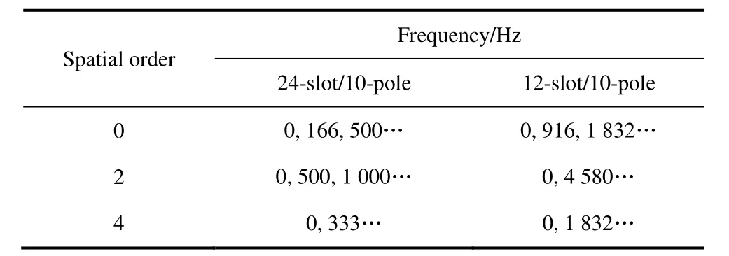
Tab.2 Frequency of axial force with lower spatial orders
From Tab.2,it is evident that the frequency of every electromagnetic force wave is an even multiple of the electrical frequency.This observation also confirms the correctness of the prior derivation of the analytical expression for electromagnetic force waves.Given that an electromagnetic force wave with a smaller spatial order has a greater propensity to influence the motor’s vibration,efforts should be made to circumvent resonance issues arising when the frequency of this low-order electromagnetic force wave approaches the stator’s natural frequency.
3 Modal analysis
3.1 Establishment of partial structure model of stator of axial flux motor
In this study,the stator and winding of the 24-slot/10-pole axial flux motor,as well as the stator,winding,and back iron of the 12-slot/10-pole axial flux motor,are modeled.To expedite the 3D finite element simulation calculations,the model was simplified.Figs.7 and 8 display the three-dimensional structural models of the two axial flux motors.Tab.3 provides details on the specific parameters of the materials employed in each component of the motor.
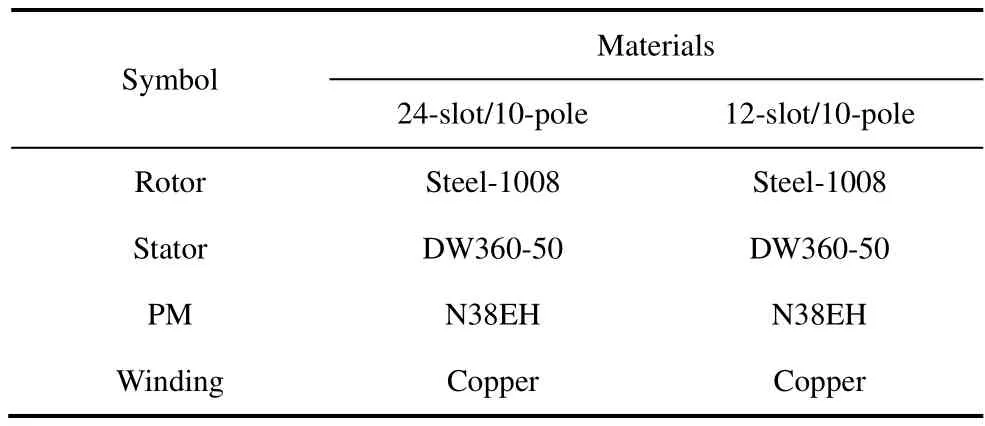
Tab.3 Specific parameters of the materials in each part of the motor
3.2 Modal finite element analysis
The electromagnetic noise of the axial flux motor is due to the axial electromagnetic force acting on the stator core,which leads to electromagnetic vibration of the stator core.The stator core was connected to the casing,which transmitted vibrations to the fuselage.Therefore,the vibration and noise characteristics of an axial flux motor should be studied using a stator core.
When analyzing the natural frequency and corresponding mode shapes of the stator system,the constraint condition is set to the state of free vibration in space (without constraint),the number of solutions is set to 80,the range of natural frequency is set to 0-20 000 Hz,and modes of order 0,2,and 4 are obtained.After setting the relevant parameters,the natural frequencies and modes were determined.
The modal shapes and frequencies of the stators of the 24-slot/10-pole and 12-slot/10-pole axial flux motors are listed in Tab.4 and Tab.5.
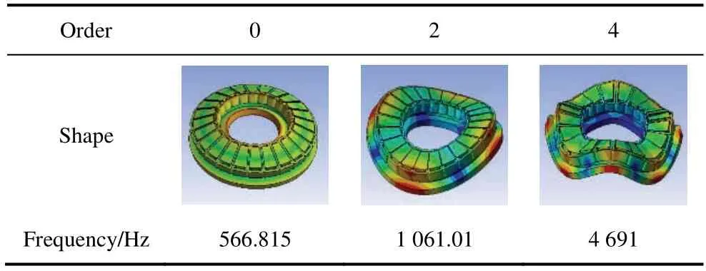
Tab.4 Modal simulation of 24-slot/10-pole axial flux motor

Tab.5 Modal simulation of 12-slot/10-pole axial flux motor
According to the analysis in Section 2,the power-supply frequency of the 24-slot/10-pole motor is 83.33 Hz.Therefore,the power-supply frequency of 499.98 Hz is approximately six times the natural frequency of the 0-order mode,and the power-supply frequency of 999.96 Hz is approximately 12 times the natural frequency of the 2-order mode.When the spatial order of the electromagnetic force of six times the power supply frequency is 0,or the spatial order of the electromagnetic force of 12 times the power supply frequency is 2,the stator core produces a more significant resonance,resulting in strong vibration noise in the axial flux motor.
As shown in Tab.4 and Tab.5,the natural frequency of the stator system of an axial flux motor increases with increases in the stator modal order.In the figure from Tabs.4-5,the degree of deformation of the stator yoke is low,whereas that of the stator is high.Most regions were located at the stator tooth end and edge.However,this is only a deformation process under ideal conditions and does not represent the deformation process in the actual operation of the motor.
Additionally,when Tab.4 and Tab.5 are combined,results indicate that the stator stiffness of the 12-slot/10-pole axial flux motor exceeds that of the 24-slot/10-pole axial flux motor,which is especially evident when the mode order is low.When the modal order increases,the natural frequencies of the stators of the two motors gradually approach each other.However,given differences in the electromagnetic force frequencies of the two motors,it is uncertain whether the vibration of the 12-slot/10-pole axial flux motor exceeds that of the 24-slot/10-pole axial flux motor.
3.3 Modal test
To verify the reliability of the finite element simulation results,a modal test was performed on the stator of a 24-slot/10-pole axial flux motor.
Fig.9 shows the back iron and permanent magnet,and Fig.10 shows the stator iron and winding of the 24-slot/10-pole axial flux motor.
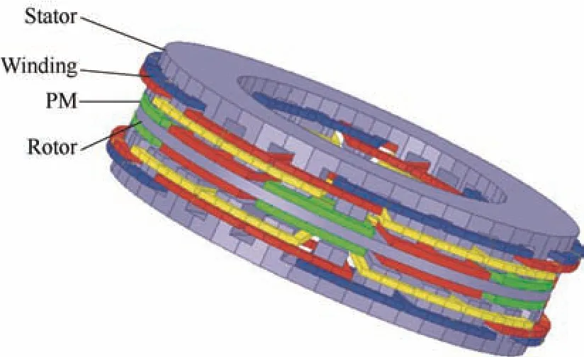
Fig.1 Finite element model of the 24-slot/10-pole axial flux motor

Fig.2 Finite element model of the 12-slot/10-pole axial flux motor
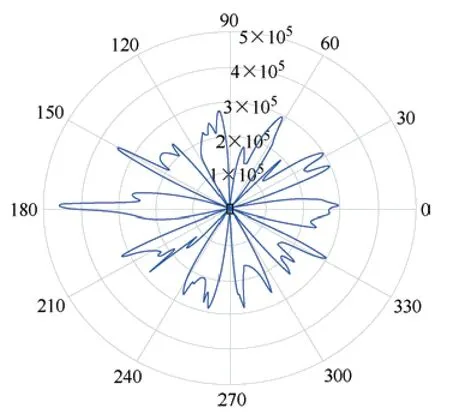
Fig.3 Maxwell simulation results of spatial distribution of axial electromagnetic force of 24-slot,10-pole axial flux motor
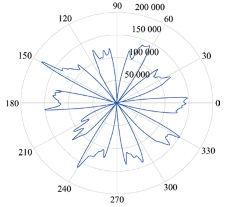
Fig.4 Maxwell simulation results of spatial distribution of axial electromagnetic force of 12-slot/10-pole axial flux motor
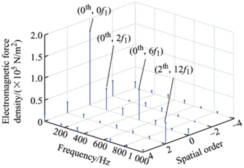
Fig.5 2-D FFT of the 24-slot/10-pole axial flux motor
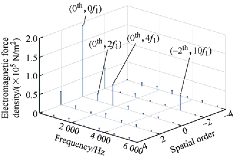
Fig.6 2-D FFT of the 12-slot/10-pole axial flux motor
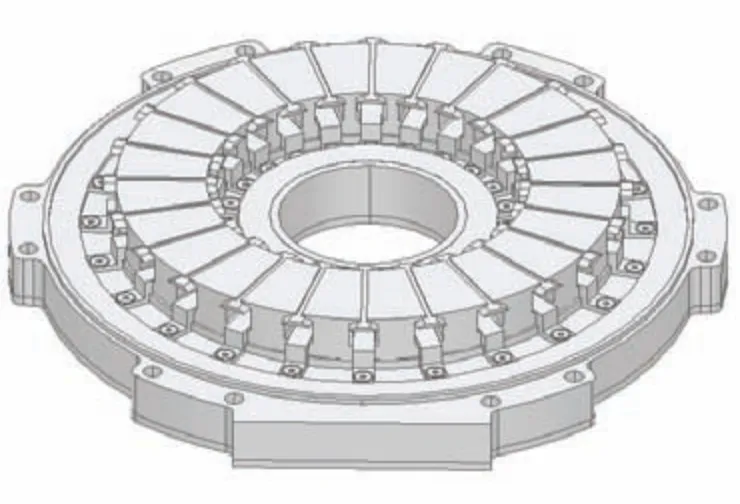
Fig.7 Stator of 24-slot/10-pole axial flux motor
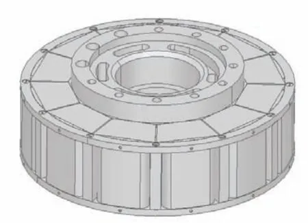
Fig.8 Stator of 12-slot/10-pole axial flux motor
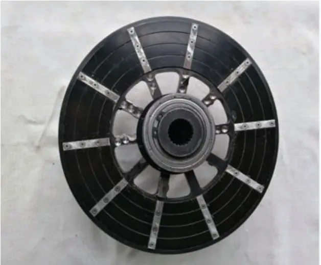
Fig.9 Back iron and PM
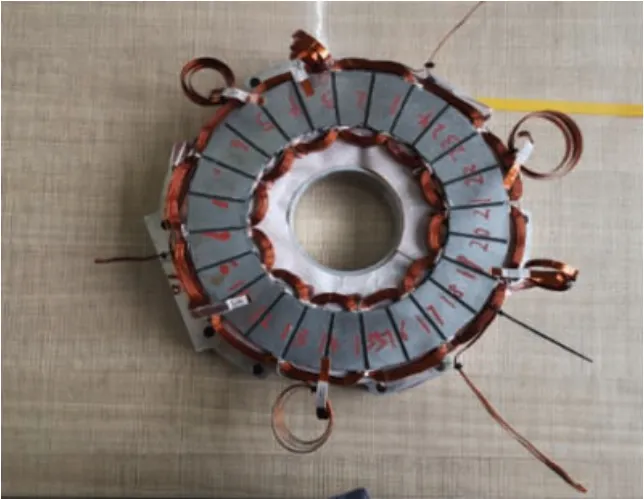
Fig.10 Stator iron and stator windings
We used a modal force hammer to exert an impact force on the structure,and an axial acceleration sensor to measure the acceleration of the shaft.The parameters of the modal force hammer and axial acceleration sensor are listed in Tab.6.The analysis software used was LMS Test Lab Modal Analysis,LMS Test Lab Automatic Modal Parameter Selection,and LMS Test Lab Poly MAX module.The compatibility of data formats and interfaces should be considered when performing software coordination.The modal experimental process was as follows.

Tab.6 Parameters of the modal force hammer and axial acceleration sensor
The hammer method was used to establish 24×2=48 vibration measurement points on the positive and negative sides of the stator disk.The directions of the excitation and picking points were along the normal directions of the structural surface.The excitation direction was inward,and the picking direction was outward.To decrease the error caused by the sensor,the measurement was repeated thrice at each point,and experimental data with good coherence were selected for modal parameter identification.The PolyMax method was used for identification in the LMS Test Lab.A modal experimental flowchart is shown in Fig.11.The modal experimental platform is shown in Fig.12.
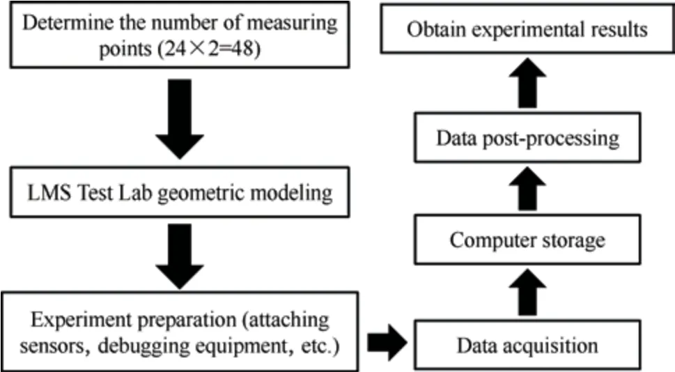
Fig.11 Modal experimental flowchart
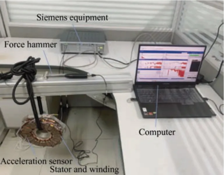
Fig.12 Modal test platform
The experimental results measured on the modal experimental platform,as shown in Fig.12,are post-processed,and the final extracted modal parameters are listed in Tab.7,which are compared with the finite element modal parameters listed in Tab.4.The modal shapes are in good agreement with those obtained using the finite-element method.In terms of modal frequencies,the frequency errors of the other modal orders are low,except for the 0 mode frequency,which satisfies the requirements for reasonable engineering errors and verifies the accuracy of the established structural finite element model.Increases in error in the 0 order mode frequency can be attributed to the minimum 0 order mode frequency of the axial flux motor.

Tab.7 Modal experiment results
When combined with the analysis of the axial electromagnetic force in the preamble,resonance can easily occur in the stator system when the spatial order of the electromagnetic force is equal to a certain modal order of the stator system and the frequency of the electromagnetic force of this spatial order is close to the modal frequency of the corresponding order.Moreover,the modal experiment and simulation errors of the stator of the 24-slot/10-pole axial flux motor were only 8.7% at order 0,and the errors of orders 2 and 4 were 0.4% and 1.6%,respectively.
4 Electromagnetic vibration and noise of axial flux motor
When an axial flux motor is operating,its noise is primarily composed of electromagnetic noise.This type of electromagnetic noise is caused by the vibration of the stator tooth end face due to the periodic electromagnetic excitation force during motor operation.Eventually,these vibrations were transmitted through the outer casing to the external environment.Therefore,it is necessary to analyze its vibration response to better examine the noise of an axial flux motor.
4.1 Vibration and noise analysis flow of axial flux motor
In the first two sections,a three-dimensional air-gap magnetic field analysis and partial modal analysis of the motor stator are performed for the axial flux motor,which provides a foundation for the analysis of the motor vibration response.In this section,the harmonic response analysis module in Workbench is used to analyze and calculate the vibration of the axial flux motor,and the calculation results of harmonic response analysis are imported into the acoustic module to further analyze the noise of the axial flux motor.Finally,we obtained a noise waterfall diagram for the motor at 0-6 000 r/min.Fig.13 shows a flowchart of the harmonic response and noise analyses of the axial flux motor.

Fig.13 Flow chart of vibration noise calculation using the finite element method

Fig.14 Spectrum of vibration displacement in Z direction of the 24-slot/10-pole motor

Fig.15 Spectrum of vibration displacement in Z direction of the 12-slot/10-pole motor

Fig.16 Vibration acceleration spectrum of the 24-slot/10-pole motor

Fig.17 Vibration acceleration spectrum of the 12-slot/10-pole motor
4.2 Comparison of vibration of two axial flux motor
Ten time-varying electromagnetic forces obtained by electromagnetic calculations were used as the excitation sources,and the constraint conditions of the vibration harmonic response were specified.The vibration characteristics of the motor are obtained via simulations.Finally,the observation point on the surface of the motor housing was selected to obtain the vibration acceleration and displacement spectrum curves of the observation point.It is should be noted that attention is generally focused only on the axial vibration displacement and vibration acceleration of the observation point for axial flux motors,which differs from radial motors.
Figs.14 and 15 show a simulation comparison ofZdirection displacement of the electromagnetic vibrations of the 24-slot/10-pole and 12-slot/10-pole axial flux motors.Based on the simulation results,the maximumZvibration amplitude of the 24-slot/10-pole axial flux motor was 0.007 mm while the maximumZvibration amplitude of the 12-slot/10-pole axial flux motor was only 6 μm.Based on the analysis in Section 3,this can be attributed to the significant resonance of the 24-slot/10-pole motor at frequencies of 500 Hz and 1 000 Hz.The vibration noise of the motor was higher in this frequency range.The vibration displacement of the 12-slot/10-pole motor was mainly higher at 1 832 Hz and 2 548 Hz,which was also caused by resonance.Therefore,it can be inferred that the natural frequency of the 12-slot/10-pole motor exceeds that of the 24-slot/10-pole motor.The vibration displacement amplitudes of the two motors in theX-axis direction slightly differ because the vibration of the axial flux motor is mainly axial vibration caused by the axial electromagnetic force.Therefore,the vibration displacement in the radial direction is low.
Figs.16 and 17 show the vibration-acceleration curves of the two axial-flux motors.As shown in the figures,except for the resonance frequencies of 500 Hz and 1 000 Hz,the vibration acceleration of the 12-slot/10-pole motor in the other frequency ranges significantly exceeded that of the 24-slot/10-pole motor.This can lead to severe vibrations and noise.Therefore,it can be concluded that the vibration noise of the 24-slot/10-pole motor exceeded that of the 12-slot/10-pole motor.
4.3 Finite element analysis of noise of 24-slot/10-pole axial flux motor
A waterfall diagram of the noise spectrum of the 24-slot/10-pole motor in the speed range of 0-6 000 r/min was obtained via the coupling calculation of the structural field,as shown in Fig.18.The main concentration of high noise occurred in the high-speed area,and this was primarily because the axial force frequency of the motor was close to the natural frequency of the motor stator in the high-speed area,which resulted in resonance.Additionally,in the low-frequency band,there are high-noise areas near 500 Hz and 1 000 Hz,which correspond to the modal analysis of the 24-slot/10-pole motor discussed in Section 3.This is because the frequencies of the inherent modes of orders 0 and 2 of the stator of the 24-slot/10-pole motor are close to those of orders 0 and 2 of the axial electromagnetic force,thereby leading to stator resonance.

Fig.18 Noise waterfall at 0-6 000 r/min of 24-slot/10-pole axial flux motor
4.4 Noise experiment of 24-slot/10-pole axial flux motor
In this section,a noise test was conducted for the 24-slot/10-pole axial flux motor.Fig.19 shows the test platform.To decrease the error caused by other noises at the experimental site and the effect of the airflow generated by the rotor rotation to the maximum possible extent,the microphone should be arranged at a height of 10 cm above the motor.
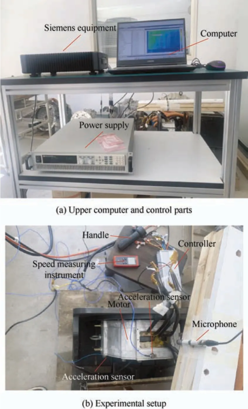
Fig.19 Noise test platform of the 24-slot/10-pole axial flux motor
Fig.20 shows the simulation results of noise at 1 000 r/min,in which the two maximum peak frequencies were approximately 500 Hz and 1 000 Hz,respectively.These results are consistent with the simulation results and are 6 and 12 times the power supply frequency,respectively.

Fig.20 Measured noise at 1 000 r/min
Fig.21 shows the time-domain diagram of the noise detected by the microphone at 0-1 000 r/min.The area bounded by dotted lines in the figure is the noise in the“fixed region” due to structural resonance,and the corresponding 0-order and 2-order structural modes can be obtained from Tab.7.Among the modes,the noise caused by the resonance in mode 0 was the highest.This is because the amplitude of the electromagnetic force of order 0 in low frequency band is the highest.Conversely,the low-frequency electromagnetic force is affected by low-order current harmonics,and its frequency is relatively dense.
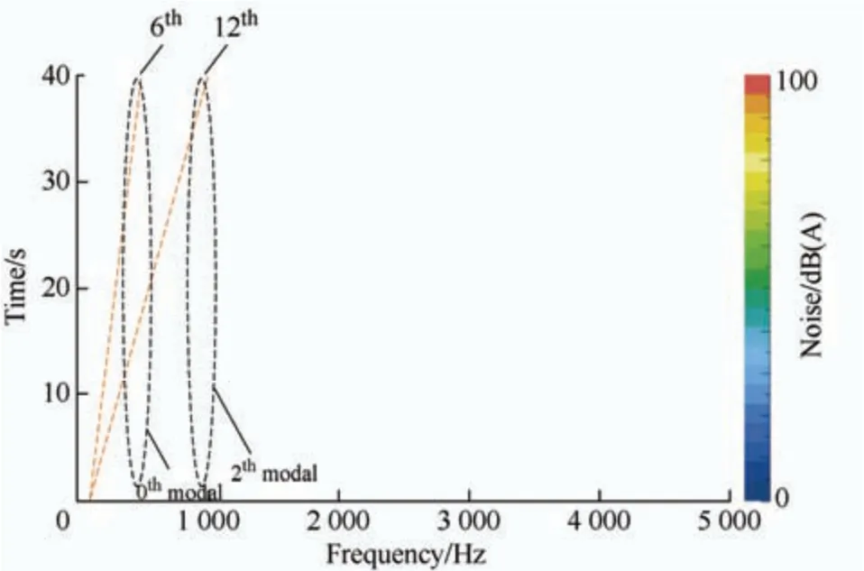
Fig.21 Measured noise under accelerated conditions
5 Conclusions
In the study,Maxwell finite element software was used to develop a simulation model,calculate electromagnetic force under different slots,and perform Fourier decomposition of the obtained electromagnetic force.A modal simulation analysis and 3D transient structure field vibration simulation of the axial flux motor were performed,and the effect of different grooves and pole matching on the electromagnetic vibration of the axial flux motor was analyzed.The conclusions of this study are as follows.
(1) (0,6f1),and (2,12f1) are the main influences of the 24-slot/10-pole motors on vibration and noise.As indicated by the modal experiments,the 0-order axial mode frequency of the 24-slot/10-pole motor is 521.449 Hz and is close to 6f1=499.98 Hz.At this time,the motor stator generates resonance if the spatial order of the electromagnetic force is zero,which is the reason for high vibration noise at 500 Hz.The main effects of the 12-slot/10pole motor on the vibration and noise were (0,4f1) and (2,6f1),respectively.
(2) By comparing the finite element results of the natural frequencies of the two types of motor stator systems,it was concluded that the stator stiffness of the 12-slot/10-pole motor was higher.By observing the finite element simulation results of the vibration acceleration and displacement of the two motors,it is concluded that the vibration noise of the 12-slot/10-pole motor is slightly less than that of the 24-slot/10-pole motor only in the vicinity of 500 Hz and 1 000 Hz because the stator of the 24-slot/10-pole motor resonates in the vicinity of 500 Hz and 1 000 Hz.However,the vibration noise of the 12-slot/10-pole motor was greater in other frequency ranges.In general,12-slot/10-pole motors are more prone to resonance.
(3) In contrast to the radial-flux motor,the frequency of the zero-order mode of the axial-flux motor stator system was the lowest,and second-order mode frequency was not lower than zero-order mode frequency.
 Chinese Journal of Electrical Engineering2023年4期
- Chinese Journal of Electrical Engineering的其它文章
- A Review of Isolated Bidirectional DC-DC Converters for Data Centers*
- Review of Hybrid Packaging Methods for Power Modules*
- Vibration Reduction and Torque Improvement of Integral-slot SPM Machines Using PM Harmonic Injection*
- Calculation of Available Transfer Capability Using Hybrid Chaotic Selfish Herd Optimizer and 24 Hours RES-thermal Scheduling
- Filtered High Gain Observer for an Electric Vehicle’s Electro-hydraulic Brake: Design and Optimization Using Multivariable Newton-based Extremum Seeking
- Improved Approaches Toward Analysis of Electromagnetic Processes in Electrodynamical Devices Based on the Theory of Electromagnetic Field
