Distributed Control Software for the Active Surface System of Tian-ma Radio Telescope
Dong Zhang,Rong-Bing Zhao ,Zhen Yan ,Wei-Hua Shang-Guan ,Qian Ye ,Zhi-Qiang Shen ,Qing-Hui Liu ,Jin-Qing Wang , Li Fu , Chu-Yuan Zhang , Dong-Fang Song, and Si-Yu Liu,3
1 Shanghai Astronomical Observatory, Chinese Academy of Sciences, Shanghai 200030, China; zhaorb@shao.ac.cn
2 University of Chinese Academy of Sciences, Beijing 100049, China
3 Chongqing Jiaotong University, Chongqing 400074, China
Abstract The Tian-ma Radio Telescope (TMRT) applies an Active Surface System (ASFS), which corrects for large-scale deformations due to gravity and thermal on the primary reflector.The centralized and automated management of the ASFS using software has become a challenge,for which we have developed the TMRT Active Surface System Control Software (TASCS).This paper describes the design and implementation of TASCS for device control,status monitoring, human-computer interaction, and data management functionalities.TASCS adopts the opensource Tango Controls framework and distributes middleware technology to realize real-time automated adjustment of the primary reflector through remote centralized control of a large number of actuators.At present,it has been successfully deployed on the TMRT and has played an important role in Event Horizon Telescope observations.
Key words:Astronomical Instrumentation–Methods and Techniques–telescopes–instrumentation:high angular resolution – techniques: high angular resolution
1.Introduction
Due to the large size and weight,a large-aperture antenna is susceptible to large-scale distortion caused by gravity and thermal, thus reducing the antenna efficiency.At present, the international large radio telescopes, such as Green Bank Telescope (GBT), Sardinia Radio Telescope (SRT), and Tianma Radio Telescope(TMRT),have adopted the Active Surface System (ASFS).ASFS can recover the ideal shape of the primary reflector by adjusting the actuators to improve the antenna efficiency.
TMRT is currently the largest and fully steerable Cassegraintype radio telescope system in Asia.The ASFS of TMRT is equipped with 1104 actuators to provide real-time adjustments to the 1008 panels of the primary reflector.Figure 1 (Dong et al.2018) demonstrates a significant improvement in the antenna efficiency when the ASFS works in the Q-band(35–50 GHz).
The control software plays the role of the brain in ASFS.It is responsible for coordinating all devices and monitoring their working status.In view of the large number of devices and the complexity structure of the ASFS, we adopted the distributed control framework to design and develop the software.The distributed control framework has many advantages,such as by hiding the details of the underlying mechanisms (such as message queues, asynchronous communication, thread pools,and lifecycle management) to helping engineers improve development efficiency; by standardizing device attributes and behaviors (such as data structures, interfaces, protocols,state machines) to provide a unified resource sharing and invocation for the system.Internationally, several large radio telescopes have adopted the distributed control framework for their ASFS, such as the Alma Common Software (ACS;Chiozzi et al.2004 and Shen et al.2011), Ygor (Ford &Clark 2002 and Ford et al.2014), and Tango Controls (Baffa et al.2019).
In this paper,we have designed and implemented the TMRT Active Surface System Control Software (TASCS) using Tango Controls.As an open source, cross-platform, and object-oriented distributed system framework, Tango Controls have good scalability, rich application programming interfaces(API),and a series of practical toolkits (Verdier et al.2011).It can help users realize the functions of device control, data acquisition and real-time transmission.Therefore, it is an ideal choice for the implementation of the control software of ASFS.
The following text will first introduce the hardware of the ASFS briefly.Then, the software will be described from the following three aspects: design, implementation, and testing.
2.Hardware
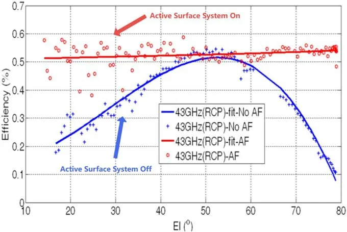
Figure 1.Q-band efficiency with the active surface system on and off.
The ASFS of TMRT consists of actuators, control buses,subcabinets,and control software.The system is equipped with a total of 1104 actuators, which are installed on the back structure of the antenna (Dong et al.2016).The antenna panel position is adjusted by controlling the four adaptive screws on the actuators.The ASFS utilizes an RS-485 bus to connect all actuators to the Ethernet (see Figure 2) and is divided into 24 fan sections.Each section is controlled by a subcabinet which includes three buses,so the system includes 72 buses.Each bus connects 15 or 16 actuators.
3.Design
3.1.Function Design
TASCS is designed to meet the diverse needs of its users,including astronomers, observation engineers, and more.Therefore, it contains the following functionalities:
1.Monitoring and control:
Continuously collect and analyze the device status information and raise alarms for system abnormalities.
Read the Antenna Deformation Model (ADM) from the database, calculate the optimal displacement for each actuator at the current elevation, and move the actuators to the desired position.
2.Human-machine interaction:
Provide remote access for multiple users through a graphical user interface (GUI).
Display real-time status of the devices.
Provide a device debugging interface for the users.
3.Data management:
Access to the ADM.
Store device status data and record log files.
3.2.Architecture Design
TASCS adopts the open-source Tango Controls framework which utilizes the CORBA (Common Object Request Broker Architecture) middleware technology (Götz et al.2003).The core concept of Tango Controls is based on device and device class.Device, as the control object, represents either physical hardware device or logical device.It has unified features,including attributes, properties, pipes, and commands, which are defined by device class.Device object is instantiated within device server which acts as a container process (Tan 2015).
As shown in Figure 3, Device Server includes the Actuator-Bus Device Server,Coordinator Device Server,and Subcabinet Device Server.Client includes Device Control,Data Visualization and Debugging functions.Communication between Device Server and Client is done using the Tango Middleware Protocol.The Database consists of the Tango Database and Model Database.
3.3.Model Design
We use the Unified Modeling Language(UML)to model the software structure,as shown in Figure 4.Actuator-Bus inherits from DeviceImpl base class and realizes the initial configuration, state acquisition, and operation control of the actuator through customized code.Actuator-Bus Class defines the unified interface characteristics of Actuator-Bus including attributes, commands, and properties.The attributes include the actuator’s position, speed, temperature, current, and alarm status; the properties include the actuator’s address and number; the commands include the actuator’s startup, shutdown, start operation, stop operation, and abnormality recovery.
4.Implementation
TASCS contains modules such as Actuator-Bus Device Server, Coordinator Device Server, State Machine, GUI,Database, and Logging.The specific implementation of each module will be described below.
4.1.Actuator-Bus Device Server
The Actuator-Bus Device Server is the core part of the whole software, which takes a bus as the control object.As shown in Figure 5, the Actuator-Bus Device Server first reads the ADM from the model database and calculates the optimal displacement of each actuator according to the command,then calls the device driver interface to control the actuator.At the same time,it collects the status data of the actuator in real time,pushes it to the client and records the log file.
4.2.Coordinator Device Server
Due to the numerous devices of the radio telescope, we use the Coordinator Device Server (hereinafter referred to as coordinator)to synchronize the various devices of the telescope during the observation process (see Figure 6).
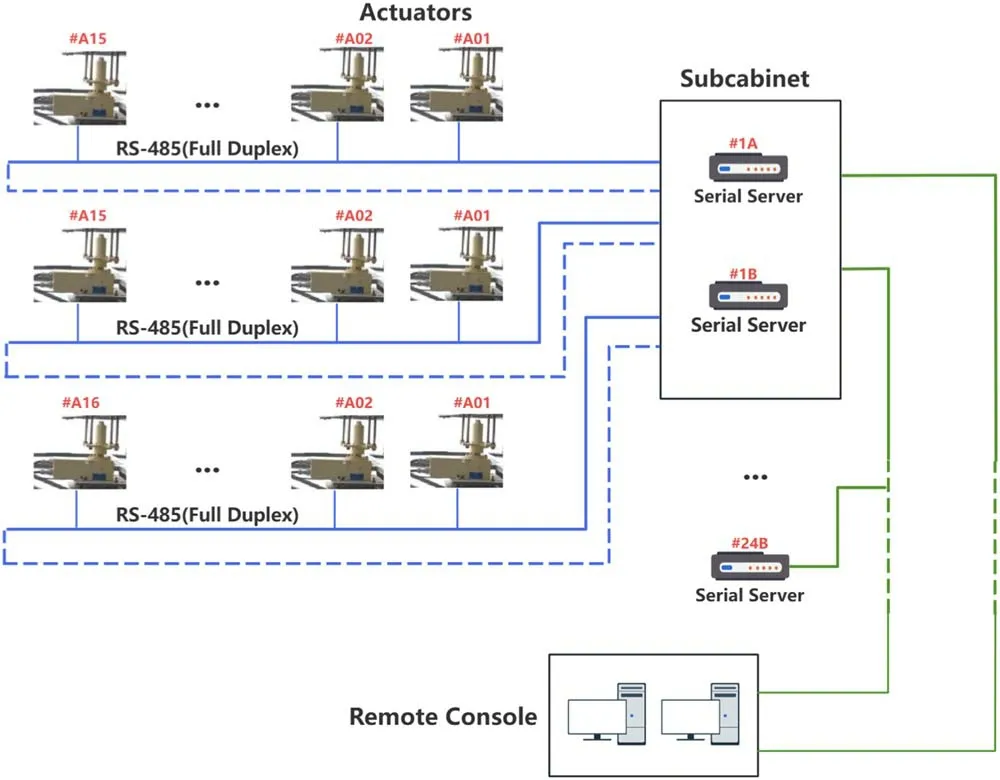
Figure 2.The communication network of the ASFS.
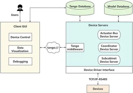
Figure 3.Architecture design for TASCS.
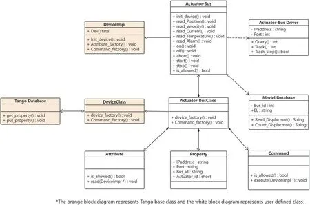
Figure 4.UML diagram for TASCS.
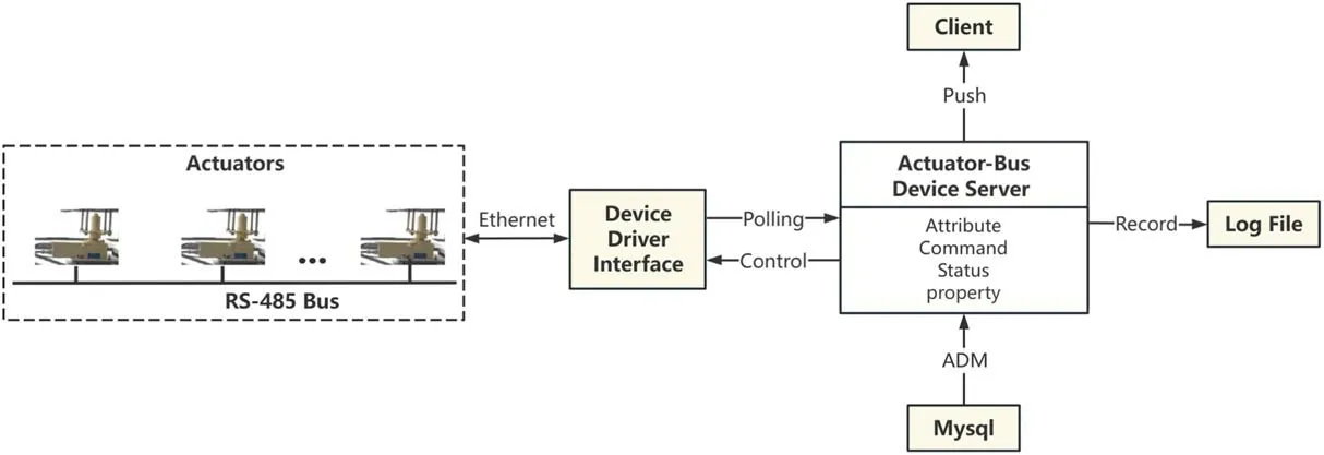
Figure 5.Execution logic diagram for Actuator-Bus Device Server.
Generally, a complete observation process consists of three stages: the preparation stage, the observation stage and the termination stage.During the preparation stage, the antenna needs to move toward the target, the receiver is required to configure parameters, and the ASFS needs to adjust the panel position.In order to ensure that all devices are ready before starting the observation, the coordinator calculates the Synchronization Start Time (SST) based on the preparation time spent by each device and distributes the SST to all device servers.Subsequently, each device server autonomously manages its corresponding device.For example, the antenna has pointed to the target;the ASFS has adjusted the actuators to the optimal position; the Data Acquisition System (DAS) is ready for recording data.After reaching the SST, the antenna starts tracking, the ASFS starts real-time adjustment, and the DAS starts recording data.During the termination stage, all devices stop running and return to their initial state.
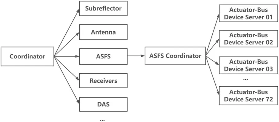
Figure 6.Coordinator structure diagram.
4.3.State Machine
In order to unify the behavior of the actuators so that it operates according to a strict timing sequence, we use a state machine to describe the various working states of the actuators and the transition methods between different states.As shown in Figure 7,after powering-on,the actuators are initialized and configured with parameters to transition to the “Ready” state.When receiving the command from the coordinator, each actuator enters the “Activate” state.At this time, all actuators move toward the target position.After reaching the synchronization start time, they enter the “Running” state and make real-time adjustments based on the current elevation.During operation, if there is an abnormality in the system, such as device failure or transmission error, the actuators stop running and enter the “Standby” state.
4.4.Graphical User Interface (GUI)
The GUI is developed using Python language, PyQt5, and OpenGL library.The interface consists of three parts: Device Control, Data Visualization, and Debugging (see Figure 8).Device Control provides users with the interface for device control.Data Visualization displays real-time device state information.Debugging provides users with the device debugging interface for analyzing and troubleshooting device faults.
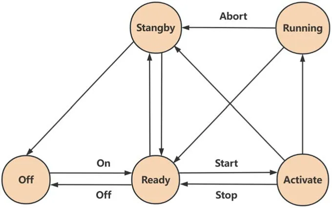
Figure 7.Actuator state machine.
4.5.Database
The database consists of Tango database and a model database.The Tango database provides the device configuration information and runtime catalog for both client and device servers (Tan 2015).The ADM is stored in the model database which records the displacement of each actuator at every elevation.
4.6.Logging
The logging module is used to record the historical states of the ASFS.The module records the position and running mileage of all actuators and the state information of each device for system recovery and troubleshooting.
5.Measurement Results
Currently, TASCS has been successfully deployed on the TMRT and plays an important role in Event Horizon Telescope(EHT)observations(Akiyama et al.2019).It is mainly used in the following two cases during observations:
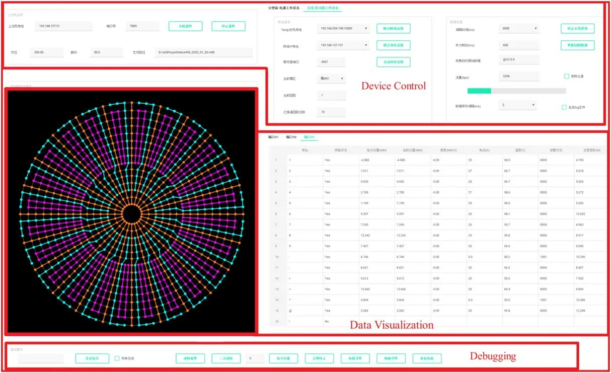
Figure 8.User interface.
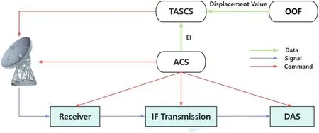
Figure 9.Control logic of the software system for the ASFS.
In the first case, the surface error of the primary reflector is measured using Out-of-Focusholography technique (Nikolic et al.2007 and Dong et al.2014) prior to the observation.TASCS converts the surface error into displacement values for the actuators and makes corresponding adjustments.
In the second case,Antenna Control Software(ACS)guides the antenna to track the target during the observation.It sends the current elevation to TASCS which reads the ADM and adjusts the panel position in real time.
The control logic diagram for the ASFS is shown in Figure 9.
After enabling TASCS,we conducted surface measurements on the primary reflector and achieved a surface accuracy of rms 201 microns (see Figure 10), meeting our expectations.
6.Conclusion and Discussion
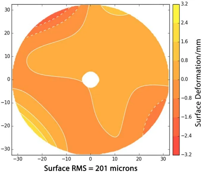
Figure 10.Surface accuracy of the primary reflector after adjustment.
This paper designs and implements TASCS which uses Tango Controls as the distributed control framework, C/S design mode, and C++ and Python language.TASCS is capable of multi-user remote control and monitoring, easy upgrades, flexible and cross-platform deployment.During actual operation, TASCS automatically adjusts the primary reflector by actuators according to the ADM, thus improving the surface accuracy.Considering the advantages of Tango Controls in building distributed control systems, we will adopt it in more radio telescope projects in the future.
Acknowledgments
This work was supported by the National SKA Program of China, No.2020SKA0120104 and the Natural Science Foundation of Shanghai, No.20ZR1467600.
ORCID iDs
Rong-Bing Zhao https://orcid.org/0000-0002-1868-9665 Zhen Yan https://orcid.org/0000-0002-9322-9319 Wei-Hua Shang-Guan https://orcid.org/0000-0002-7312-1108
Qian Ye https://orcid.org/0000-0002-4167-0823
Zhi-Qiang Shen https://orcid.org/0000-0003-3540-8746 Qing-Hui Liu https://orcid.org/0000-0003-0517-6390
Jin-Qing Wang https://orcid.org/0000-0002-4321-3255
Li Fu https://orcid.org/0000-0001-7530-6336
Chu-Yuan Zhang https://orcid.org/0000-0002-8617-2510
 Research in Astronomy and Astrophysics2023年11期
- Research in Astronomy and Astrophysics的其它文章
- Photometric and Spectroscopic Study of Two Low Mass Ratio Contact Binary Systems: CRTS J225828.7-121122 and CRTSJ030053.5+230139
- Injection Spectra of Different Species of Cosmic Rays from AMS-02, ACECRIS and Voyager-1
- The AIMS Site Survey
- A High-Temperature Superconducting Wideband Bandpass Filter at the L Band for Radio Astronomy
- Modified Masses and Parallaxes of Close Binary Systems: HD 39438
- Detecting HI Galaxies with Deep Neural Networks in the Presence of Radio Frequency Interference
